1999 NISSAN PRIMERA Control
[x] Cancel search: ControlPage 835 of 2267
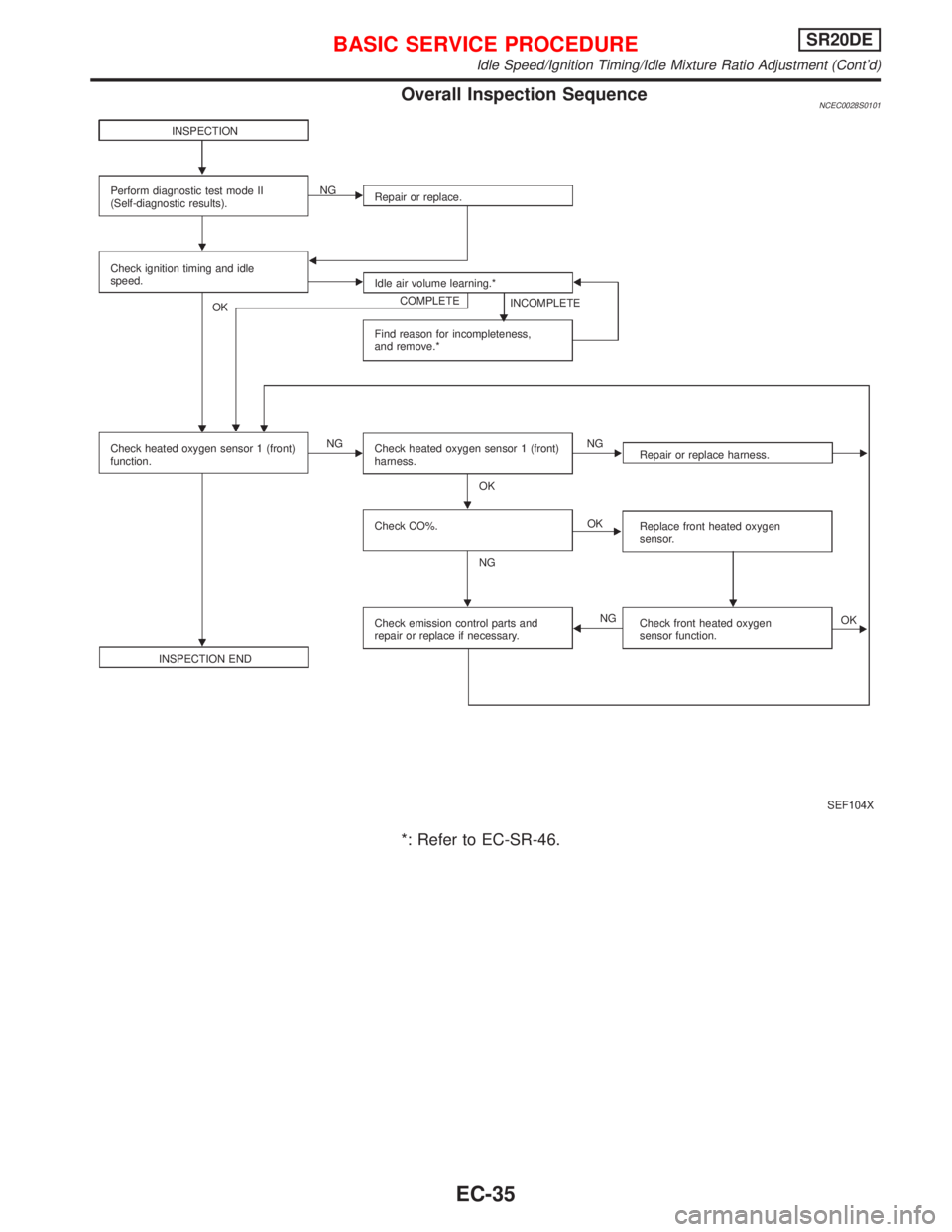
Overall Inspection SequenceNCEC0028S0101
*: Refer to EC-SR-46.
SEF104X INSPECTION
Perform diagnostic test mode II
(Self-diagnostic results).Repair or replace. NG
Check ignition timing and idle
speed.
Idle air volume learning.*
COMPLETE
INCOMPLETE
Find reason for incompleteness,
and remove.* OK
Check heated oxygen sensor 1 (front)
function.NG
Check heated oxygen sensor 1 (front)
harness.NG
OK
Check CO%.
NGOK
INSPECTION ENDCheck emission control parts and
repair or replace if necessary.NGRepair or replace harness.
Replace front heated oxygen
sensor.
Check front heated oxygen
sensor function.OK H
BASIC SERVICE PROCEDURESR20DE
Idle Speed/Ignition Timing/Idle Mixture Ratio Adjustment (Cont'd)
EC-35
Page 849 of 2267
Emission-related Diagnostic InformationNCEC0031DTC AND 1ST TRIP DTCNCEC0031S01The 1st trip DTC (whose number is the same as the DTC number) is displayed for the latest self-diagnostic
result obtained. If the ECM memory was cleared previously, and the 1st trip DTC did not reoccur, the 1st trip
DTC will not be displayed. If a malfunction is detected during the 1st trip, the 1st trip DTC is stored in the ECM
memory. The MI will not light up (two trip detection logic). If the same malfunction is not detected in the 2nd
trip (meeting the required driving pattern), the 1st trip DTC is cleared from the ECM memory. If the same mal-
function is detected in the 2nd trip, both the 1st trip DTC and DTC are stored in the ECM memory and the MI
lights up. In other words, the DTC is stored in the ECM memory and the MI lights up when the same malfunc-
tion occurs in two consecutive trips. If a 1st trip DTC is stored and a non-diagnostic operation is performed
between the 1st and 2nd trips, only the 1st trip DTC will continue to be stored. For malfunctions that blink or
light up the MI during the 1st trip, the DTC and 1st trip DTC are stored in the ECM memory.
Procedures for clearing the DTC and the 1st trip DTC from the ECM memory are described in ªHOW TO
ERASE EMISSION-RELATED DIAGNOSTIC INFORMATIONº. Refer to EC-SR-56.
For malfunctions in which 1st trip DTCs are displayed, refer to EC-SR-54. These items are required by legal
regulations to continuously monitor the system/component. In addition, the items monitored non-continuously
are also displayed on CONSULT-II.
1st trip DTC is specified in Mode 7 of ISO 15031-5. 1st trip DTC detection occurs without lighting up the MI
and therefore does not warn the driver of a problem. However, 1st trip DTC detection will not prevent the
vehicle from being tested, for example during Inspection/Maintenance (I/M) tests.
When a 1st trip DTC is detected, check, print out or write down and erase (1st trip) DTC and Freeze Frame
data as specified in ªWork Flowº procedure Step II, refer to page EC-SR-82. Then perform ªDTC Confirma-
tion Procedureº or ªOverall Function Checkº to try to duplicate the problem. If the malfunction is duplicated,
the item requires repair.
How to read DTC and 1st Trip DTCNCEC0031S0101DTC and 1st trip DTC can be read by the following methods.
1)
No Tools
The number of blinks of MI in the Diagnostic Test Mode II (Self-Diagnostic Results) Examples: 0340, 1320,
0705, 0750, etc.
These DTCs are controlled by NISSAN.
2)
With CONSULT-II
With GST
CONSULT-II or GST (Generic Scan Tool) Examples: P0340, P1320, P0705, P0750, etc.
These DTCs are prescribed by ISO 15031-6.
(CONSULT-II also displays the malfunctioning component or system.)
I1st trip DTC No. is the same as DTC No.
IOutput of a DTC indicates a malfunction. However, Mode II and GST do not indicate whether the
malfunction is still occurring or has occurred in the past and has returned to normal.
CONSULT-II can identify malfunction status as shown below. Therefore, using CONSULT-II (if avail-
able) is recommended.
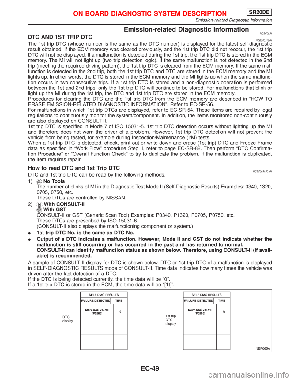
A sample of CONSULT-II display for DTC is shown below. DTC or 1st trip DTC of a malfunction is displayed
in SELF-DIAGNOSTIC RESULTS mode of CONSULT-II. Time data indicates how many times the vehicle was
driven after the last detection of a DTC.
If the DTC is being detected currently, the time data will be ª0º.
If a 1st trip DTC is stored in the ECM, the time data will be ª[1t]º.
NEF065A DTC
display1st trip
DTC
display
ON BOARD DIAGNOSTIC SYSTEM DESCRIPTIONSR20DE
Emission-related Diagnostic Information
EC-49
Page 851 of 2267
Together with the DTC, the SRT code is cleared from the ECM memory using the method described later
(Refer to EC-SR-56). In addition, after engine control components/system are repaired or if the battery termi-
nals remain disconnected for more than 24 hours, all SRT codes may be cleared from the ECM memory.
How to Display SRT CodeNCEC0031S03011.With CONSULT-II
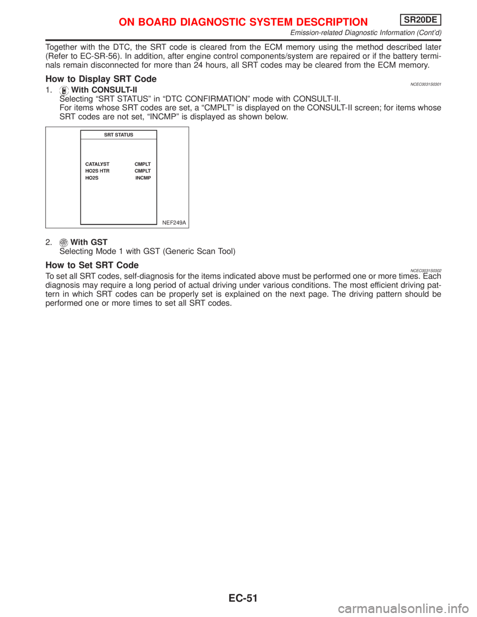
Selecting ªSRT STATUSº in ªDTC CONFIRMATIONº mode with CONSULT-II.
For items whose SRT codes are set, a ªCMPLTº is displayed on the CONSULT-II screen; for items whose
SRT codes are not set, ªINCMPº is displayed as shown below.
2.
With GST
Selecting Mode 1 with GST (Generic Scan Tool)
How to Set SRT CodeNCEC0031S0302To set all SRT codes, self-diagnosis for the items indicated above must be performed one or more times. Each
diagnosis may require a long period of actual driving under various conditions. The most efficient driving pat-
tern in which SRT codes can be properly set is explained on the next page. The driving pattern should be
performed one or more times to set all SRT codes.
NEF249A
ON BOARD DIAGNOSTIC SYSTEM DESCRIPTIONSR20DE
Emission-related Diagnostic Information (Cont'd)
EC-51
Page 855 of 2267
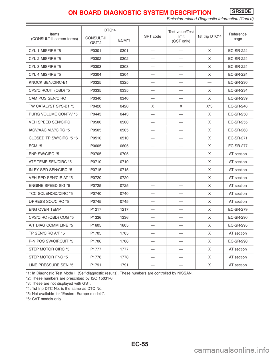
Items
(CONSULT-II screen terms)DTC*4
SRT codeTest value/Test
limit
(GST only)1st trip DTC*4Reference
page CONSULT-II
GST*2ECM*1
CYL 1 MISFIRE *5 P0301 0301 Ð Ð X EC-SR-224
CYL 2 MISFIRE *5 P0302 0302 Ð Ð X EC-SR-224
CYL 3 MISFIRE *5 P0303 0303 Ð Ð X EC-SR-224
CYL 4 MISFIRE *5 P0304 0304 Ð Ð X EC-SR-224
KNOCK SEN/CIRC-B1 P0325 0325 Ð Ð Ð EC-SR-230
CPS/CIRCUIT (OBD) *5 P0335 0335 Ð Ð X EC-SR-234
CAM POS SEN/CIRC P0340 0340 Ð Ð X EC-SR-239
TW CATALYST SYS-B1 *5 P0420 0420 X X X*3 EC-SR-246
PURG VOLUME CONT/V *5 P0443 0443 Ð Ð X EC-SR-250
VEH SPEED SEN/CIRC P0500 0500 Ð Ð X EC-SR-255
IACV/AAC VLV/CIRC *5 P0505 0505 Ð Ð X EC-SR-263
CLOSED TP SW/CIRC *5 *6 P0510 0510 Ð Ð X EC-SR-271
ECM *5 P0605 0605 Ð Ð X EC-SR-277
PNP SW/CIRC *5 P0705 0705 Ð Ð X AT section
ATF TEMP SEN/CIRC *5 P0710 0710 Ð Ð X AT section
IN PY SPD SEN/CIRC *5 P0715 0715 Ð Ð X AT section
VEH SPD SEN/CIR AT *5 P0720 0720 Ð Ð X AT section
ENGINE SPEED SIG *5 P0725 0725 Ð Ð X AT section
TCC SOLENOID/CIRC *5 P0740 0740 Ð Ð X AT section
L/PRESS SOL/CIRC *5 P0745 0745 Ð Ð X AT section
ENG OVER TEMP P1217 1217 Ð Ð X EC-SR-279
CPS/CIRC (OBD) COG *5 P1336 1336 Ð Ð X EC-SR-290
A/T DIAG COMM LINE *5 P1605 1605 Ð Ð X EC-SR-295
TP SEN/CIRC A/T *5 P1705 1705 Ð Ð X AT section
P-N POS SW/CIRCUIT *5 P1706 1706 Ð Ð X EC-SR-298
STEP MOTOR CIRC *5 P1777 1777 Ð Ð X AT section
STEP MOTOR FNC *5 P1778 1778 Ð Ð X AT section
LINE PRESSURE SEN *5 P1791 1791 Ð Ð X AT section
*1: In Diagnostic Test Mode II (Self-diagnostic results). These numbers are controlled by NISSAN.
*2: These numbers are prescribed by ISO 15031-6.
*3: These are not displayed with GST.
*4: 1st trip DTC No. is the same as DTC No.
*5: Not available for ªEastern Europe modelsº.
*6: CVT models only
ON BOARD DIAGNOSTIC SYSTEM DESCRIPTIONSR20DE
Emission-related Diagnostic Information (Cont'd)
EC-55
Page 856 of 2267
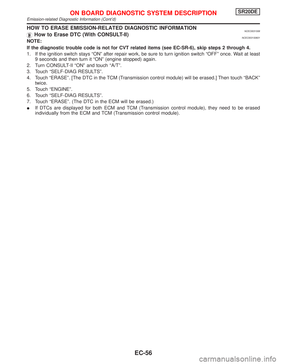
HOW TO ERASE EMISSION-RELATED DIAGNOSTIC INFORMATIONNCEC0031S06How to Erase DTC (With CONSULT-II)NCEC0031S0601NOTE:
If the diagnostic trouble code is not for CVT related items (see EC-SR-6), skip steps 2 through 4.
1. If the ignition switch stays ªONº after repair work, be sure to turn ignition switch ªOFFº once. Wait at least
9 seconds and then turn it ªONº (engine stopped) again.
2. Turn CONSULT-II ªONº and touch ªA/Tº.
3. Touch ªSELF-DIAG RESULTSº.
4. Touch ªERASEº. [The DTC in the TCM (Transmission control module) will be erased.] Then touch ªBACKº
twice.
5. Touch ªENGINEº.
6. Touch ªSELF-DIAG RESULTSº.
7. Touch ªERASEº. (The DTC in the ECM will be erased.)
IIf DTCs are displayed for both ECM and TCM (Transmission control module), they need to be erased
individually from the ECM and TCM (Transmission control module).
ON BOARD DIAGNOSTIC SYSTEM DESCRIPTIONSR20DE
Emission-related Diagnostic Information (Cont'd)
EC-56
Page 859 of 2267
DESCRIPTIONNCEC0032
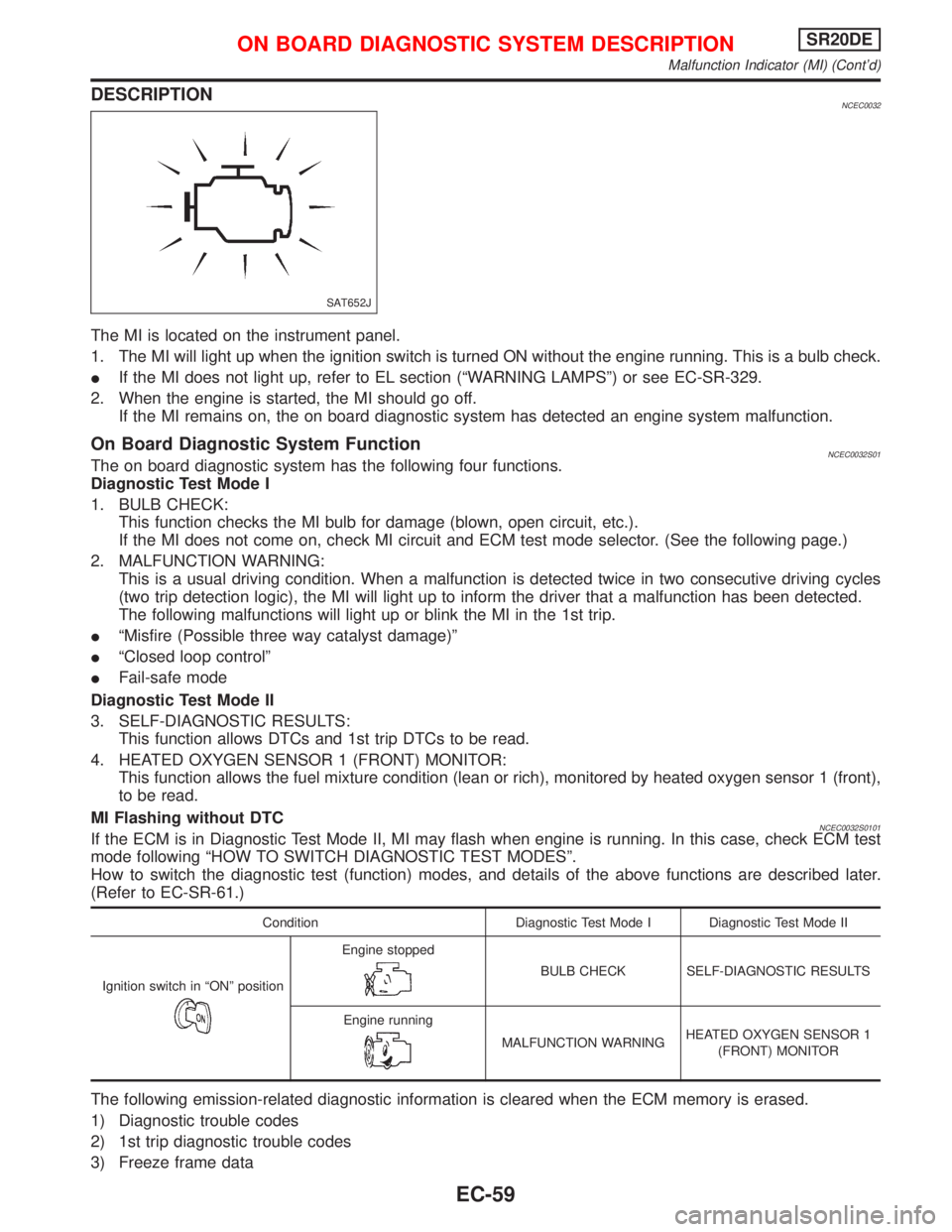
The MI is located on the instrument panel.
1. The MI will light up when the ignition switch is turned ON without the engine running. This is a bulb check.
IIf the MI does not light up, refer to EL section (ªWARNING LAMPSº) or see EC-SR-329.
2. When the engine is started, the MI should go off.
If the MI remains on, the on board diagnostic system has detected an engine system malfunction.
On Board Diagnostic System FunctionNCEC0032S01The on board diagnostic system has the following four functions.
Diagnostic Test Mode I
1. BULB CHECK:
This function checks the MI bulb for damage (blown, open circuit, etc.).
If the MI does not come on, check MI circuit and ECM test mode selector. (See the following page.)
2. MALFUNCTION WARNING:
This is a usual driving condition. When a malfunction is detected twice in two consecutive driving cycles
(two trip detection logic), the MI will light up to inform the driver that a malfunction has been detected.
The following malfunctions will light up or blink the MI in the 1st trip.
IªMisfire (Possible three way catalyst damage)º
IªClosed loop controlº
IFail-safe mode
Diagnostic Test Mode II
3. SELF-DIAGNOSTIC RESULTS:
This function allows DTCs and 1st trip DTCs to be read.
4. HEATED OXYGEN SENSOR 1 (FRONT) MONITOR:
This function allows the fuel mixture condition (lean or rich), monitored by heated oxygen sensor 1 (front),
to be read.
MI Flashing without DTC
NCEC0032S0101If the ECM is in Diagnostic Test Mode II, MI may flash when engine is running. In this case, check ECM test
mode following ªHOW TO SWITCH DIAGNOSTIC TEST MODESº.
How to switch the diagnostic test (function) modes, and details of the above functions are described later.
(Refer to EC-SR-61.)
Condition Diagnostic Test Mode I Diagnostic Test Mode II
Ignition switch in ªONº position
Engine stopped
BULB CHECK SELF-DIAGNOSTIC RESULTS
Engine running
MALFUNCTION WARNINGHEATED OXYGEN SENSOR 1
(FRONT) MONITOR
The following emission-related diagnostic information is cleared when the ECM memory is erased.
1) Diagnostic trouble codes
2) 1st trip diagnostic trouble codes
3) Freeze frame data
SAT652J
ON BOARD DIAGNOSTIC SYSTEM DESCRIPTIONSR20DE
Malfunction Indicator (MI) (Cont'd)
EC-59
Page 863 of 2267
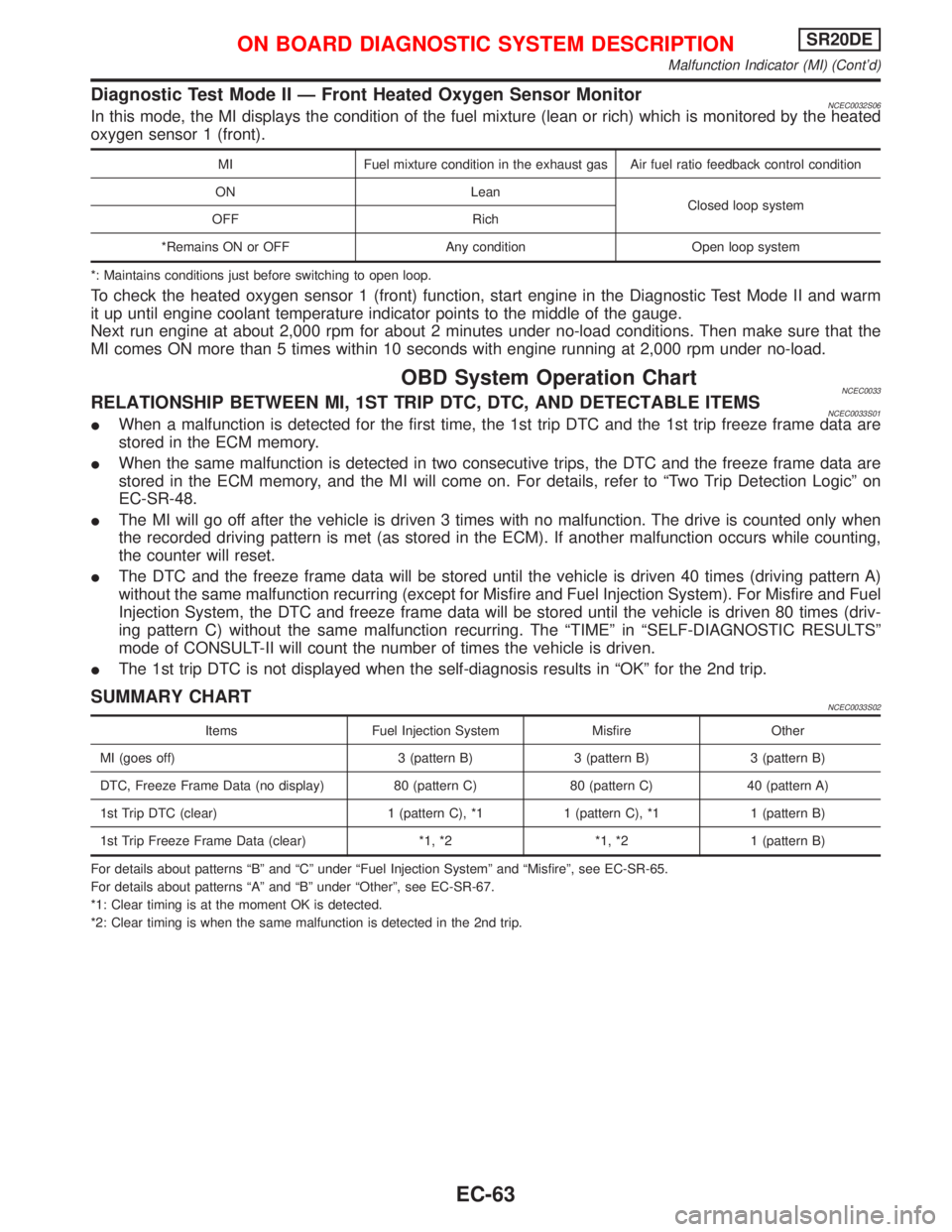
Diagnostic Test Mode II Ð Front Heated Oxygen Sensor MonitorNCEC0032S06In this mode, the MI displays the condition of the fuel mixture (lean or rich) which is monitored by the heated
oxygen sensor 1 (front).
MI Fuel mixture condition in the exhaust gas Air fuel ratio feedback control condition
ON Lean
Closed loop system
OFF Rich
*Remains ON or OFF Any condition Open loop system
*: Maintains conditions just before switching to open loop.
To check the heated oxygen sensor 1 (front) function, start engine in the Diagnostic Test Mode II and warm
it up until engine coolant temperature indicator points to the middle of the gauge.
Next run engine at about 2,000 rpm for about 2 minutes under no-load conditions. Then make sure that the
MI comes ON more than 5 times within 10 seconds with engine running at 2,000 rpm under no-load.
OBD System Operation ChartNCEC0033RELATIONSHIP BETWEEN MI, 1ST TRIP DTC, DTC, AND DETECTABLE ITEMSNCEC0033S01IWhen a malfunction is detected for the first time, the 1st trip DTC and the 1st trip freeze frame data are
stored in the ECM memory.
IWhen the same malfunction is detected in two consecutive trips, the DTC and the freeze frame data are
stored in the ECM memory, and the MI will come on. For details, refer to ªTwo Trip Detection Logicº on
EC-SR-48.
IThe MI will go off after the vehicle is driven 3 times with no malfunction. The drive is counted only when
the recorded driving pattern is met (as stored in the ECM). If another malfunction occurs while counting,
the counter will reset.
IThe DTC and the freeze frame data will be stored until the vehicle is driven 40 times (driving pattern A)
without the same malfunction recurring (except for Misfire and Fuel Injection System). For Misfire and Fuel
Injection System, the DTC and freeze frame data will be stored until the vehicle is driven 80 times (driv-
ing pattern C) without the same malfunction recurring. The ªTIMEº in ªSELF-DIAGNOSTIC RESULTSº
mode of CONSULT-II will count the number of times the vehicle is driven.
IThe 1st trip DTC is not displayed when the self-diagnosis results in ªOKº for the 2nd trip.
SUMMARY CHARTNCEC0033S02
Items Fuel Injection System Misfire Other
MI (goes off) 3 (pattern B) 3 (pattern B) 3 (pattern B)
DTC, Freeze Frame Data (no display) 80 (pattern C) 80 (pattern C) 40 (pattern A)
1st Trip DTC (clear) 1 (pattern C), *1 1 (pattern C), *1 1 (pattern B)
1st Trip Freeze Frame Data (clear) *1, *2 *1, *2 1 (pattern B)
For details about patterns ªBº and ªCº under ªFuel Injection Systemº and ªMisfireº, see EC-SR-65.
For details about patterns ªAº and ªBº under ªOtherº, see EC-SR-67.
*1: Clear timing is at the moment OK is detected.
*2: Clear timing is when the same malfunction is detected in the 2nd trip.
ON BOARD DIAGNOSTIC SYSTEM DESCRIPTIONSR20DE
Malfunction Indicator (MI) (Cont'd)
EC-63
Page 869 of 2267
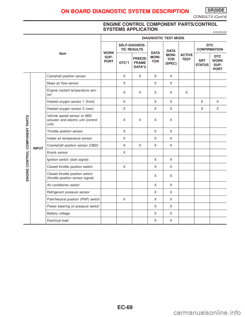
ENGINE CONTROL COMPONENT PARTS/CONTROL
SYSTEMS APPLICATION
NCEC0034S02
ItemDIAGNOSTIC TEST MODE
WORK
SUP-
PORTSELF-DIAGNOS-
TIC RESULTS
D ATA
MONI-
TORD ATA
MONI-
TOR
(SPEC)ACTIVE
TESTDTC
CONFIRMATION
DTC*1FREEZE
FRAME
DATA*2SRT
STATUSDTC
WORK
SUP-
PORT
ENGINE CONTROL COMPONENT PARTS
INPUTCamshaft position sensorXXXX
Mass air flow sensor X X X
Engine coolant temperature sen-
sorXXXXX
Heated oxygen sensor 1 (front) X X X X X
Heated oxygen sensor 2 (rear) X X X X X
Vehicle speed sensor or ABS
actuator and electric unit (control
unit)XXXX
Throttle position sensor X X X
Intake air temperature sensor X X X
Crankshaft position sensor (OBD)XXXX
Knock sensor X
Ignition switch (start signal) X X
Closed throttle position switch X X X
Closed throttle position switch
(throttle position sensor signal)XX
Air conditioner switch X X
Refrigerant pressure sensor X X
Park/Neutral position (PNP) switch X X X
Power steering oil pressure switch X X
Battery voltage X X
Electrical load X X
ON BOARD DIAGNOSTIC SYSTEM DESCRIPTIONSR20DE
CONSULT-II (Cont'd)
EC-69