Page 1432 of 2267
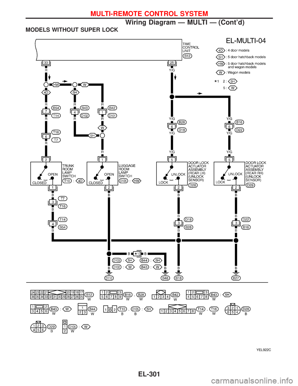
YEL921C
MULTI-REMOTE CONTROL SYSTEM
Wiring Diagram—MULTI—(Cont’d)
EL-300
Page 1433 of 2267
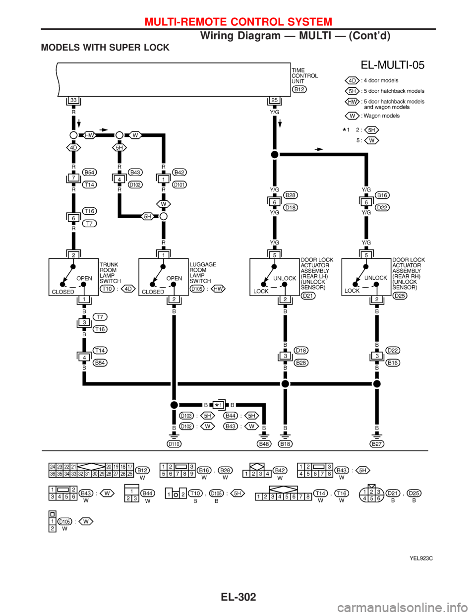
MODELS WITHOUT SUPER LOCK
YEL922C
MULTI-REMOTE CONTROL SYSTEM
Wiring Diagram—MULTI—(Cont’d)
EL-301
Page 1434 of 2267
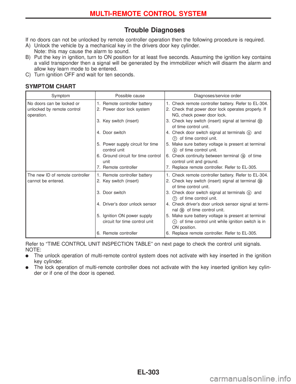
MODELS WITH SUPER LOCK
YEL923C
MULTI-REMOTE CONTROL SYSTEM
Wiring Diagram—MULTI—(Cont’d)
EL-302
Page 1435 of 2267
Trouble Diagnoses
If no doors can not be unlocked by remote controller operation then the following procedure is required.
A) Unlock the vehicle by a mechanical key in the drivers door key cylinder.
Note: this may cause the alarm to sound.
B) Put the key in ignition, turn to ON position for at least five seconds. Assuming the ignition key contains
a valid transponder then a signal will be generated by the immobilizer which will disarm the alarm and
allow key learn mode to be entered.
C) Turn ignition OFF and wait for ten seconds.
SYMPTOM CHART
Symptom Possible cause Diagnoses/service order
No doors can be locked or
unlocked by remote control
operation.1. Remote controller battery
2. Power door lock system
3. Key switch (insert)
4. Door switch
5. Power supply circuit for time
control unit
6. Ground circuit for time control
unit
7. Remote controller1. Check remote controller battery. Refer to EL-304.
2. Check that power door lock operates properly. If
NG, check power door lock.
3. Check key switch (insert) signal at terminal
�22
of time control unit.
4. Check door switch signal at terminals
�6and
�7of time control unit.
5. Make sure battery voltage is present at terminal
�9of time control unit.
6. Check continuity between terminal
�16of time
control unit and ground.
7. Replace remote controller. Refer to EL-305.
The new ID of remote controller
cannot be entered.1. Remote controller battery
2. Key switch (insert)
3. Door switch
4. Driver’s door unlock sensor
5. Ignition ON power supply
circuit for time control unit
6. Remote controller1. Check remote controller battery. Refer to EL-304.
2. Check key switch (insert) signal at terminal
�29
of time control unit.
3. Check door switch signal at terminals
�6and
�7of time control unit.
4. Check driver’s door unlock sensor signal at termi-
nal
�35of time control unit.
5. Make sure battery voltage is present at terminal
�1of time control unit while ignition switch is in
ON position.
6. Replace remote controller. Refer to EL-305.
Refer to“TIME CONTROL UNIT INSPECTION TABLE”on next page to check the control unit signals.
NOTE:
�The unlock operation of multi-remote control system does not activate with key inserted in the ignition
key cylinder.
�The lock operation of multi-remote controller does not activate with the key inserted ignition key cylin-
der or if one of the door is opened.
MULTI-REMOTE CONTROL SYSTEM
EL-303
Page 1436 of 2267
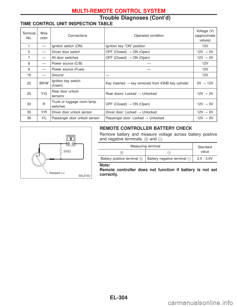
TIME CONTROL UNIT INSPECTION TABLE
Terminal
No.Wire
colorConnections Operated conditionVoltage (V)
(approximate
values)
1—Ignition switch (ON) Ignition key“ON”position 12V
5—Driver door switch OFF (Closed),ON (Open) 12V,0V
7—All door switches OFF (Closed),ON (Open) 12V,0V
8—Power source (C/B)—12V
9—Power source (Fuse)—12V
16—Ground—12V
22 BR/WIgnition key switch
(Insert)Key inserted,key removed from IGNB key cylinder 0V,12V
25 Y/GRear door unlock
sensorsRear doors: Locked,Unlocked 12V,0V
33 RTrunk or luggage room lamp
switchesOFF (Closed),ON (Open) 12V,0V
35 Y/R Driver door unlock sensor Driver door: Locked,Unlocked 12V,0V
36 Y/L Passenger door unlock sensor Passenger door: Locked,Unlocked 12V,0V
REMOTE CONTROLLER BATTERY CHECK
Remove battery and measure voltage across battery positive
and negative terminals,�and�.
Measuring terminal
Standard
value
��
Battery positive terminal�Battery negative terminal�2.5 - 3.0V
Note:
Remote controller does not function if battery is not set
correctly.
SEL672U Stamped (+)
MULTI-REMOTE CONTROL SYSTEM
Trouble Diagnoses (Cont’d)
EL-304
Page 1437 of 2267
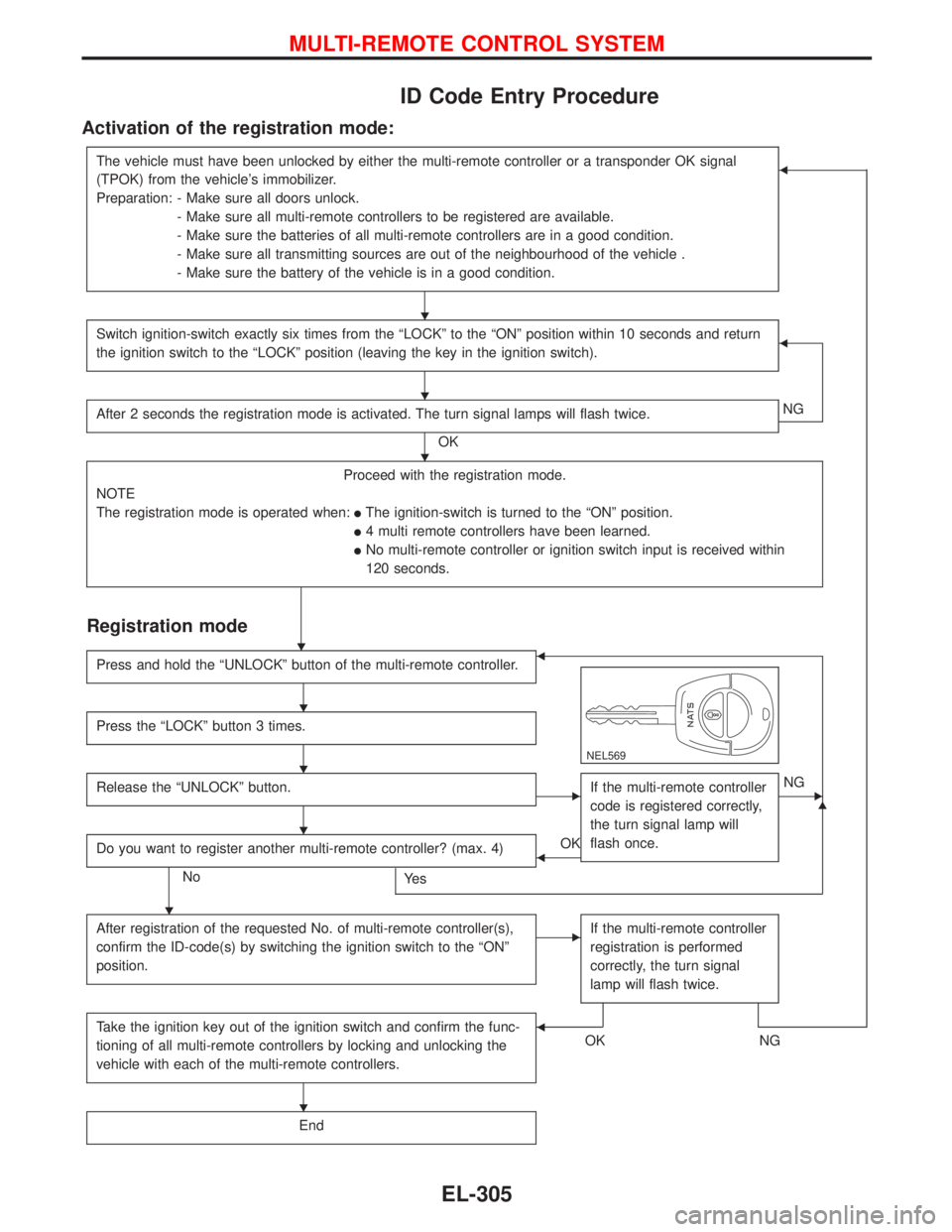
ID Code Entry Procedure
Activation of the registration mode:
The vehicle must have been unlocked by either the multi-remote controller or a transponder OK signal
(TPOK) from the vehicle’s immobilizer.
Preparation: - Make sure all doors unlock.
- Make sure all multi-remote controllers to be registered are available.
- Make sure the batteries of all multi-remote controllers are in a good condition.
- Make sure all transmitting sources are out of the neighbourhood of the vehicle .
- Make sure the battery of the vehicle is in a good condition.�
Switch ignition-switch exactly six times from the“LOCK”to the“ON”position within 10 seconds and return
the ignition switch to the“LOCK”position (leaving the key in the ignition switch).�
After 2 seconds the registration mode is activated. The turn signal lamps will flash twice.
OKNG
Proceed with the registration mode.
NOTE
The registration mode is operated when:
�The ignition-switch is turned to the“ON”position.
�4 multi remote controllers have been learned.
�No multi-remote controller or ignition switch input is received within
120 seconds.
Registration mode
�
Press and hold the“UNLOCK”button of the multi-remote controller.�
NEL569
Press the“LOCK”button 3 times.
Release the“UNLOCK”button.�If the multi-remote controller
code is registered correctly,
the turn signal lamp will
flash once.�NG
Do you want to register another multi-remote controller? (max. 4)
NoYe s
�OK
After registration of the requested No. of multi-remote controller(s),
confirm the ID-code(s) by switching the ignition switch to the“ON”
position.
�If the multi-remote controller
registration is performed
correctly, the turn signal
lamp will flash twice.
Take the ignition key out of the ignition switch and confirm the func-
tioning of all multi-remote controllers by locking and unlocking the
vehicle with each of the multi-remote controllers.OK NG�
End
�
�
�
�
�
�
�
�
�
MULTI-REMOTE CONTROL SYSTEM
EL-305
Page 1438 of 2267
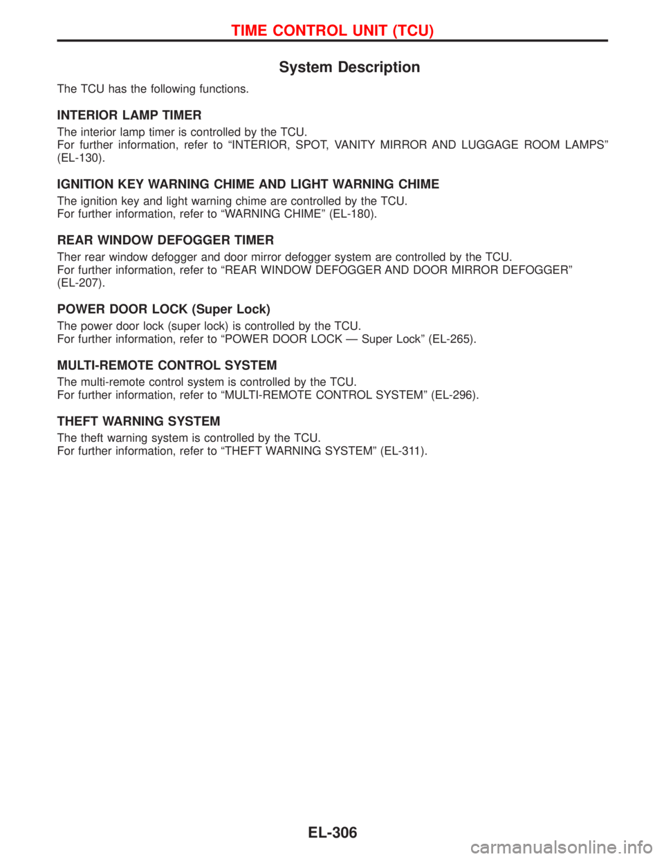
System Description
The TCU has the following functions.
INTERIOR LAMP TIMER
The interior lamp timer is controlled by the TCU.
For further information, refer to“INTERIOR, SPOT, VANITY MIRROR AND LUGGAGE ROOM LAMPS”
(EL-130).
IGNITION KEY WARNING CHIME AND LIGHT WARNING CHIME
The ignition key and light warning chime are controlled by the TCU.
For further information, refer to“WARNING CHIME”(EL-180).
REAR WINDOW DEFOGGER TIMER
Ther rear window defogger and door mirror defogger system are controlled by the TCU.
For further information, refer to“REAR WINDOW DEFOGGER AND DOOR MIRROR DEFOGGER”
(EL-207).
POWER DOOR LOCK (Super Lock)
The power door lock (super lock) is controlled by the TCU.
For further information, refer to“POWER DOOR LOCK—Super Lock”(EL-265).
MULTI-REMOTE CONTROL SYSTEM
The multi-remote control system is controlled by the TCU.
For further information, refer to“MULTI-REMOTE CONTROL SYSTEM”(EL-296).
THEFT WARNING SYSTEM
The theft warning system is controlled by the TCU.
For further information, refer to“THEFT WARNING SYSTEM”(EL-311).
TIME CONTROL UNIT (TCU)
EL-306
Page 1445 of 2267
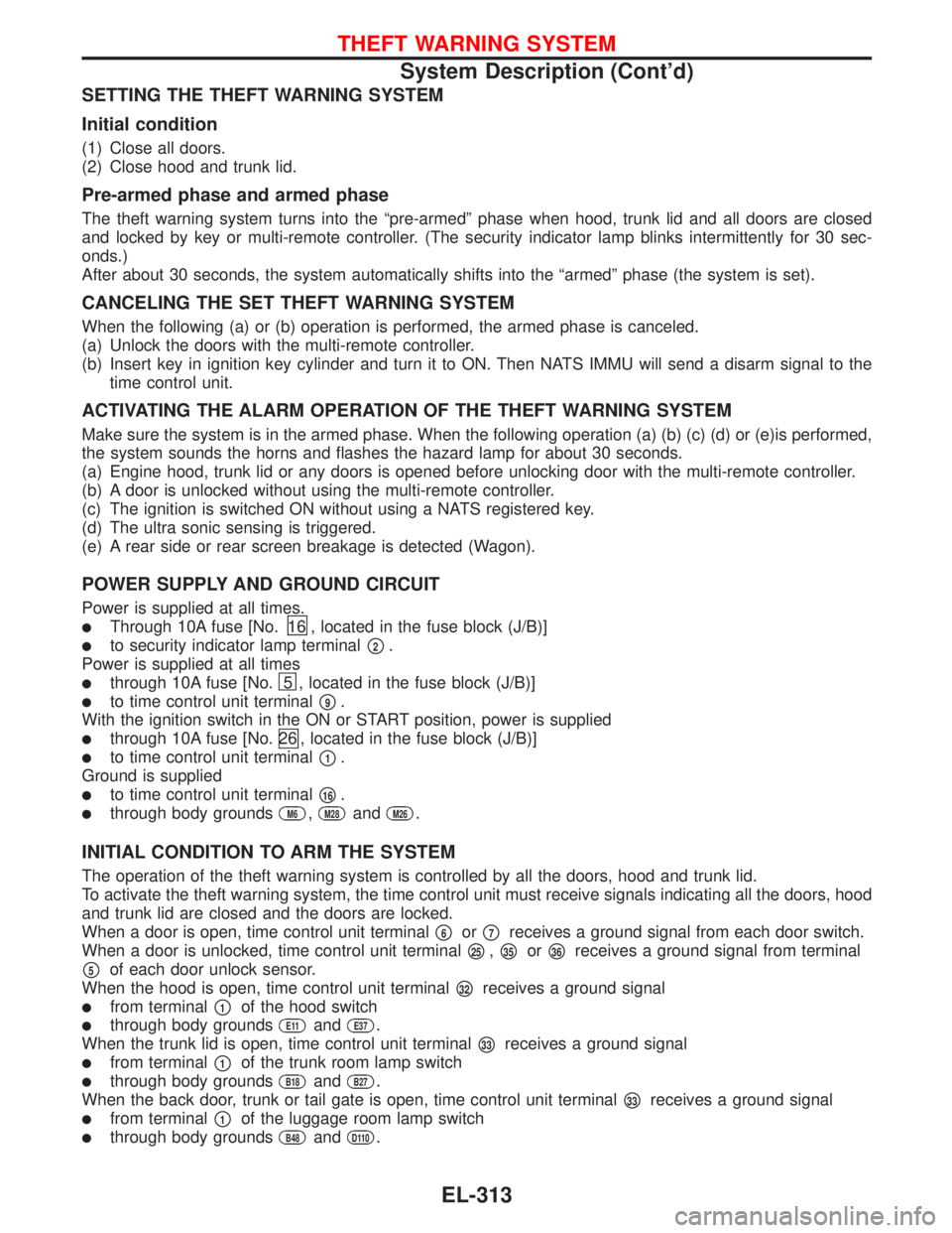
SETTING THE THEFT WARNING SYSTEM
Initial condition
(1) Close all doors.
(2) Close hood and trunk lid.
Pre-armed phase and armed phase
The theft warning system turns into the“pre-armed”phase when hood, trunk lid and all doors are closed
and locked by key or multi-remote controller. (The security indicator lamp blinks intermittently for 30 sec-
onds.)
After about 30 seconds, the system automatically shifts into the“armed”phase (the system is set).
CANCELING THE SET THEFT WARNING SYSTEM
When the following (a) or (b) operation is performed, the armed phase is canceled.
(a) Unlock the doors with the multi-remote controller.
(b) Insert key in ignition key cylinder and turn it to ON. Then NATS IMMU will send a disarm signal to the
time control unit.
ACTIVATING THE ALARM OPERATION OF THE THEFT WARNING SYSTEM
Make sure the system is in the armed phase. When the following operation (a) (b) (c) (d) or (e)is performed,
the system sounds the horns and flashes the hazard lamp for about 30 seconds.
(a) Engine hood, trunk lid or any doors is opened before unlocking door with the multi-remote controller.
(b) A door is unlocked without using the multi-remote controller.
(c) The ignition is switched ON without using a NATS registered key.
(d) The ultra sonic sensing is triggered.
(e) A rear side or rear screen breakage is detected (Wagon).
POWER SUPPLY AND GROUND CIRCUIT
Power is supplied at all times.
�Through 10A fuse [No.16 , located in the fuse block (J/B)]
�to security indicator lamp terminal�2.
Power is supplied at all times
�through 10A fuse [No.5 , located in the fuse block (J/B)]
�to time control unit terminal�9.
With the ignition switch in the ON or START position, power is supplied
�through 10A fuse [No.26 , located in the fuse block (J/B)]
�to time control unit terminal�1.
Ground is supplied
�to time control unit terminal�16.
�through body groundsM6,M28andM26.
INITIAL CONDITION TO ARM THE SYSTEM
The operation of the theft warning system is controlled by all the doors, hood and trunk lid.
To activate the theft warning system, the time control unit must receive signals indicating all the doors, hood
and trunk lid are closed and the doors are locked.
When a door is open, time control unit terminal
�6or�7receives a ground signal from each door switch.
When a door is unlocked, time control unit terminal
�25,�35or�36receives a ground signal from terminal
�5of each door unlock sensor.
When the hood is open, time control unit terminal
�32receives a ground signal
�from terminal�1of the hood switch
�through body groundsE11andE37.
When the trunk lid is open, time control unit terminal
�33receives a ground signal
�from terminal�1of the trunk room lamp switch
�through body groundsB18andB27.
When the back door, trunk or tail gate is open, time control unit terminal
�33receives a ground signal
�from terminal�1of the luggage room lamp switch
�through body groundsB48andD110.
THEFT WARNING SYSTEM
System Description (Cont’d)
EL-313