Page 139 of 2267
Installation
CAUTION:
lRefill with new brake fluid ªDOT 4º.
lNever reuse drained brake fluid.
1. Place master cylinder onto brake booster and secure mount-
ing nuts lightly.
2. Torque mounting nuts.
: 14 - 17 N´m (1.5 - 1.7 kg-m, 11 - 12 ft-lb)
3. Fill up reservoir tank with new brake fluid.
4. Plug all ports on master cylinder with fingers to prevent air
suction while releasing brake pedal.
5. Have driver depress brake pedal slowly several times until no
air comes out of master cylinder.
6. Fit brake lines to master cylinder.
7. Tighten flare nuts.
: 15 - 18 N´m (1.5 - 1.8 kg-m, 11 - 13 ft-lb)
8. Connect fluid level connector.
9. Bleed air from brake system. Refer to ªBleeding Brake
Systemº, BR-8.
SBR236E
MASTER CYLINDER
BR-17
Page 140 of 2267
On-vehicle Service
OPERATING CHECK
1. Depress brake pedal several times with engine off. After
exhausting vacuum, make sure there is no change in pedal
stroke.
2. Depress brake pedal, then start engine. If pedal goes down
slightly, operation is normal.
AIRTIGHT CHECK
1. Start engine, and stop it after one or two minutes. Depress
brake pedal several times slowly. Booster is airtight if pedal
stroke is less each time.
2. Depress brake pedal while engine is running, and stop
engine with pedal depressed. The pedal stroke should not
change after holding pedal down for30 seconds.
Removal
CAUTION:
lBe careful not to splash brake fluid on painted areas; it
may cause paint damage. If brake fluid is splashed on
painted areas, wash it away with water immediately.
lBe careful not to deform or bend brake pipes, during
removal of booster.
SBR002A
SBR365AA OK NG
Third
Second
First
NBR437
BRAKE BOOSTER
BR-18
Page 141 of 2267

Inspection
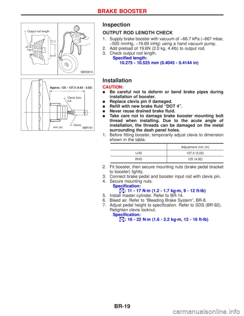
OUTPUT ROD LENGTH CHECK
1. Supply brake booster with vacuum of þ66.7 kPa (þ667 mbar,
þ500 mmHg, þ19.69 inHg) using a hand vacuum pump.
2. Add preload of 19.6N (2.0 kg, 4.4lb) to output rod.
3. Check output rod length.
Specified length:
10.275 - 10.525 mm (0.4045 - 0.4144 in)
Installation
CAUTION:
lBe careful not to deform or bend brake pipes during
installation of booster.
lReplace clevis pin if damaged.
lRefill with new brake fluid ªDOT 4º.
lNever reuse drained brake fluid.
lTake care not to damage brake booster mounting bolt
thread when installing. Due to the acute angle of
installation, the threads can be damaged on the metal
surrounding the dash panel holes.
1. Before fitting booster, temporarily adjust clevis to dimension
shown in the table.
Adjustment mm (in)
LHD 127.5 (5.02)
RHD 125 (4.92)
2. Fit booster, then secure mounting nuts (brake pedal bracket
to booster) lightly.
3. Connect brake pedal and booster input rod with clevis pin.
4. Secure mounting nuts.
Specification:
: 11 - 17 N´m (1.2 - 1.7 kg-m,9-12ft-lb)
5. Install master cylinder. Refer to BR-14.
6. Bleed air. Refer to ªBleeding Brake Systemº, BR-8.
7. Adjust pedal height to specification. Refer to SDS (BR-92).
Retighten clevis locknut.
Specification:
: 16 - 22 N´m (1.6 - 2.2 kg-m, 12 - 16 ft-lb)
SBR281A Output rod length
Approx. 125 - 127.5 (4.92 - 5.02)
Clevis Clevis lock-
nut
mm (in)
NBR191
BRAKE BOOSTER
BR-19
Page 149 of 2267
REMOVAL
1. Remove the housing retaining spring.
2. Wipe away any dirt from the guide pins between the torque
member and the cylinder body.
3. Pull out the protective caps from the guide sleeves.
4. Usea7-mmALLEN key to unscrew the guide pins
from the torque member.
5. Partially remove the guide pins from the guide sleeve.
6. Pull the cylinder body manually towards the outer side of the
vehicle so that the piston is slightly pressed back.
7. Remove the cylinder body and hang it on a wire in the wheel
arch in a suitable position.
Make sure there is no strain on the brake hose piping.
8. Remove the brake pad on the piston side from the piston.
9. Remove the second brake pad from the torque member.
NBR292 Spring Cylinder bodyTorque member lug.Torque member lug Locating
holes
NBR300 Protective
caps
NBR290
Wire
Spring
FRONT DISC BRAKESR20DE - M/T
Pad Replacement (Cont'd)
BR-27
Page 172 of 2267

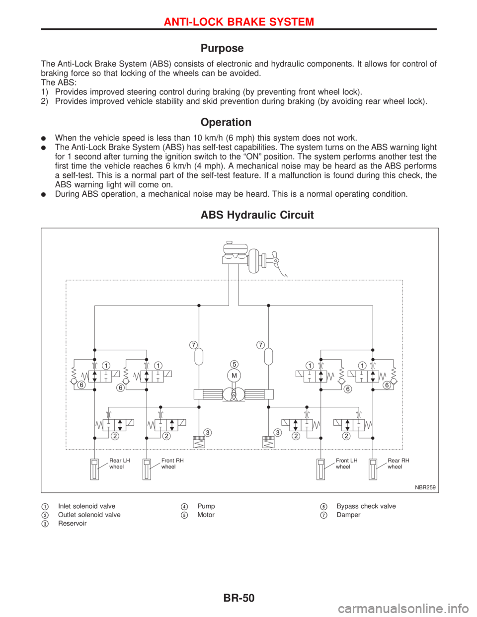
Purpose
The Anti-Lock Brake System (ABS) consists of electronic and hydraulic components. It allows for control of
braking force so that locking of the wheels can be avoided.
The ABS:
1) Provides improved steering control during braking (by preventing front wheel lock).
2) Provides improved vehicle stability and skid prevention during braking (by avoiding rear wheel lock).
Operation
lWhen the vehicle speed is less than 10 km/h (6 mph) this system does not work.
lThe Anti-Lock Brake System (ABS) has self-test capabilities. The system turns on the ABS warning light
for 1 second after turning the ignition switch to the ªONº position. The system performs another test the
first time the vehicle reaches 6 km/h (4 mph). A mechanical noise may be heard as the ABS performs
a self-test. This is a normal part of the self-test feature. If a malfunction is found during this check, the
ABS warning light will come on.
lDuring ABS operation, a mechanical noise may be heard. This is a normal operating condition.
ABS Hydraulic Circuit
p1Inlet solenoid valve
p2Outlet solenoid valve
p3Reservoir
p4Pump
p5Motorp6Bypass check valve
p7Damper
NBR259 Rear LH
wheelFront RH
wheelFront LH
wheelRear RH
wheel
ANTI-LOCK BRAKE SYSTEM
BR-50
Page 173 of 2267

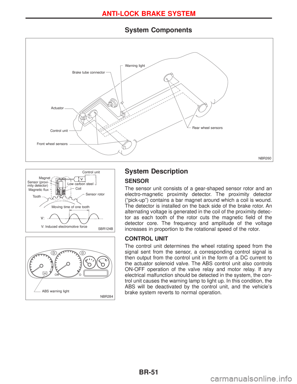
System Components
System Description
SENSOR
The sensor unit consists of a gear-shaped sensor rotor and an
electro-magnetic proximity detector. The proximity detector
(ªpick-upº) contains a bar magnet around which a coil is wound.
The detector is installed on the back side of the brake rotor. An
alternating voltage is generated in the coil of the proximity detec-
tor as each tooth of the rotor cuts the magnetic field of the
detector core. The frequency and amplitude of the voltage
increases in proportion to the rotational speed of the rotor.
CONTROL UNIT
The control unit determines the wheel rotating speed from the
signal sent from the sensor, a corresponding control signal is
then output from the control unit in the form of a DC current to
the actuator solenoid valve. The ABS control unit also controls
ON-OFF operation of the valve relay and motor relay. If any
electrical malfunction should be detected in the system, the con-
trol unit causes the warning lamp to light up. In this condition, the
ABS will be deactivated by the control unit, and the vehicle's
brake system reverts to normal operation.
NBR260 Warning light
Brake tube connector
Actuator
Front wheel sensorsControl unitRear wheel sensors
SBR124B Control unit
Magnet
.Sensor (proxi-
mity detector)
Magnetic flux
Tooth
V: Induced electromotive forceMoving time of one toothSensor rotor Coil Low carbon steel
NBR284 ABS warning light
ANTI-LOCK BRAKE SYSTEM
BR-51
Page 181 of 2267

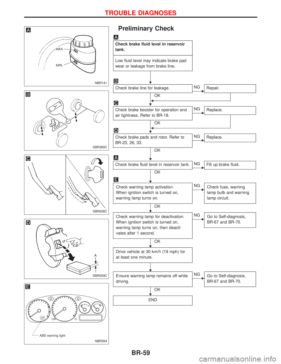
Preliminary Check
Check brake fluid level in reservoir
tank.
------------------------------------------------------------------------------------------------------------------------------------------------------------------------------------------------------------------------------------------------------------------------------------------------------------
Low fluid level may indicate brake pad
wear or leakage from brake line.
Check brake line for leakage.
OK
ENG
Repair.
F
Check brake booster for operation and
air tightness. Refer to BR-18.
OK
ENG
Replace.
F
Check brake pads and rotor. Refer to
BR-23, 26, 33.
OK
ENG
Replace.
Check brake fluid level in reservoir tank.
OK
ENG
Fill up brake fluid.
Check warning lamp activation.
When ignition switch is turned on,
warning lamp turns on.
OK
ENG
Check fuse, warning
lamp bulb and warning
lamp circuit.
Check warning lamp for deactivation.
When ignition switch is turned on,
warning lamp turns on, then deacti-
vates after 1 second.
OK
ENG
Go to Self-diagnosis,
BR-67 and BR-70.
Drive vehicle at 30 km/h (19 mph) for
at least one minute.
Ensure warning lamp remains off while
driving.
OK
ENG
Go to Self-diagnosis,
BR-67 and BR-70.
END
NBR141 MAX.
MIN.
SBR389C
SBR058C
SBR059C
.
NBR284 ABS warning light
H
H
H
H
H
H
H
H
H
TROUBLE DIAGNOSES
BR-59
Page 182 of 2267
Component Parts and Harness Connector
Location
NBR285
Brake tube connectorWarning light
ABS actuator
and electric unit
Front wheel sensors
Front left wheel sensor connector
Front right wheel sensor connector
Sensor
E17
Rear wheel sensors
Rear left wheel sensor connector
Rear right wheel sensor connector
B33Rear left wheel
sensor connector
B32Rear right wheel
sensor connector.Rear tire
.E78
E57
Sensor
TROUBLE DIAGNOSES
BR-60