1999 NISSAN PRIMERA light
[x] Cancel search: lightPage 189 of 2267
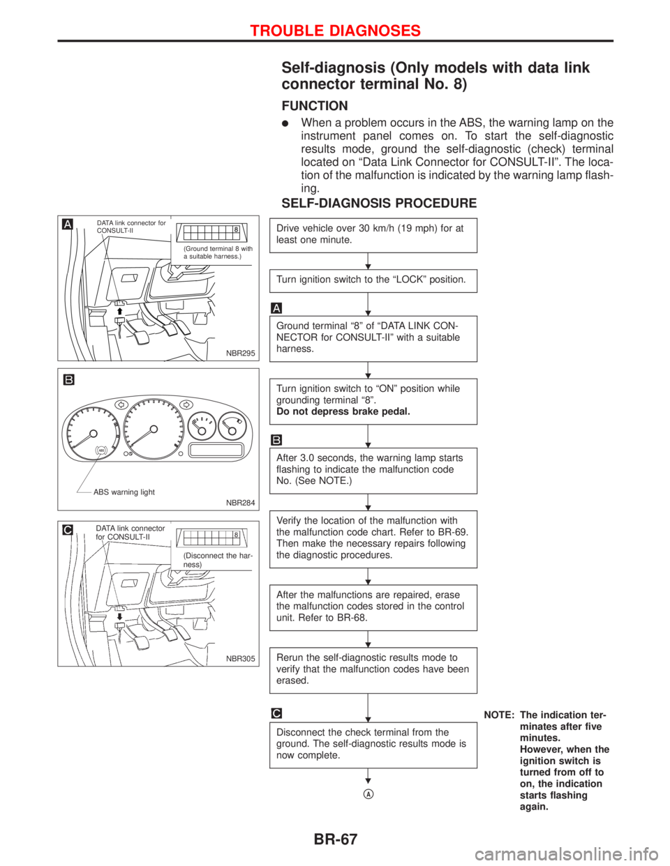
Self-diagnosis (Only models with data link
connector terminal No. 8)
FUNCTION
lWhen a problem occurs in the ABS, the warning lamp on the
instrument panel comes on. To start the self-diagnostic
results mode, ground the self-diagnostic (check) terminal
located on ªData Link Connector for CONSULT-IIº. The loca-
tion of the malfunction is indicated by the warning lamp flash-
ing.
SELF-DIAGNOSIS PROCEDURE
Drive vehicle over 30 km/h (19 mph) for at
least one minute.
Turn ignition switch to the ªLOCKº position.
Ground terminal ª8º of ªDATA LINK CON-
NECTOR for CONSULT-IIº with a suitable
harness.
Turn ignition switch to ªONº position while
grounding terminal ª8º.
Do not depress brake pedal.
After 3.0 seconds, the warning lamp starts
flashing to indicate the malfunction code
No. (See NOTE.)
Verify the location of the malfunction with
the malfunction code chart. Refer to BR-69.
Then make the necessary repairs following
the diagnostic procedures.
After the malfunctions are repaired, erase
the malfunction codes stored in the control
unit. Refer to BR-68.
Rerun the self-diagnostic results mode to
verify that the malfunction codes have been
erased.
NOTE: The indication ter-
minates after five
minutes.
However, when the
ignition switch is
turned from off to
on, the indication
starts flashing
again. Disconnect the check terminal from the
ground. The self-diagnostic results mode is
now complete.
pA
NBR295
.DATA link connector for
CONSULT-II
(Ground terminal 8 with
a suitable harness.)
NBR284 ABS warning light
NBR305
.DATA link connector
for CONSULT-II
(Disconnect the har-
ness)
H
H
H
H
H
H
H
H
H
TROUBLE DIAGNOSES
BR-67
Page 208 of 2267
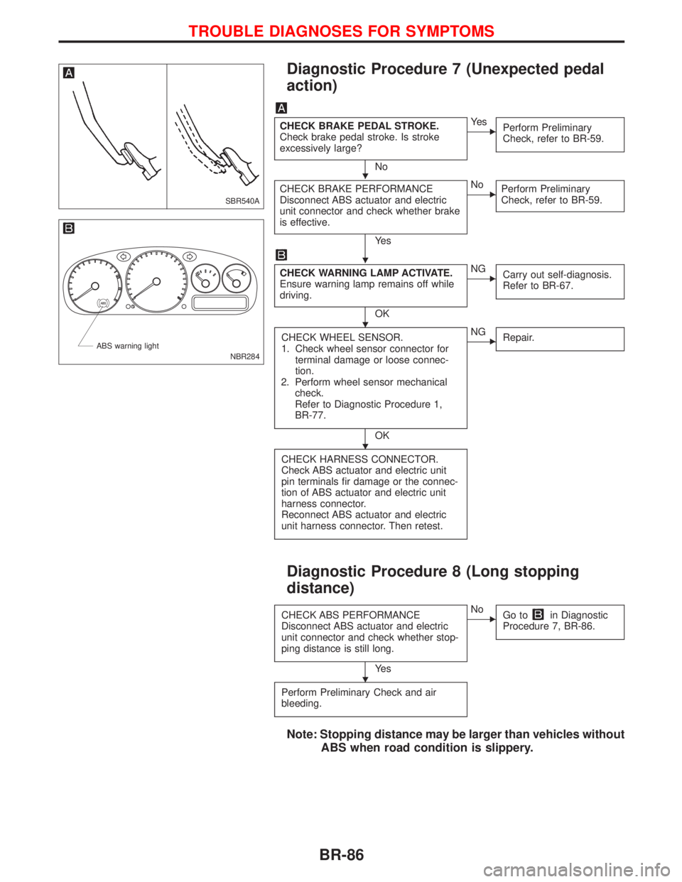
Diagnostic Procedure 7 (Unexpected pedal
action)
CHECK BRAKE PEDAL STROKE.
Check brake pedal stroke. Is stroke
excessively large?
No
EYe s
Perform Preliminary
Check, refer to BR-59.
CHECK BRAKE PERFORMANCE
Disconnect ABS actuator and electric
unit connector and check whether brake
is effective.
Ye s
ENo
Perform Preliminary
Check, refer to BR-59.
CHECK WARNING LAMP ACTIVATE.
Ensure warning lamp remains off while
driving.
OK
ENG
Carry out self-diagnosis.
Refer to BR-67.
CHECK WHEEL SENSOR.
1. Check wheel sensor connector for
terminal damage or loose connec-
tion.
2. Perform wheel sensor mechanical
check.
Refer to Diagnostic Procedure 1,
BR-77.
OK
ENG
Repair.
CHECK HARNESS CONNECTOR.
Check ABS actuator and electric unit
pin terminals fir damage or the connec-
tion of ABS actuator and electric unit
harness connector.
Reconnect ABS actuator and electric
unit harness connector. Then retest.
Diagnostic Procedure 8 (Long stopping
distance)
CHECK ABS PERFORMANCE
Disconnect ABS actuator and electric
unit connector and check whether stop-
ping distance is still long.
Ye s
ENo
Go toin Diagnostic
Procedure 7, BR-86.
Perform Preliminary Check and air
bleeding.
Note: Stopping distance may be larger than vehicles without
ABS when road condition is slippery.
SBR540A
NBR284 ABS warning light
H
H
H
H
H
TROUBLE DIAGNOSES FOR SYMPTOMS
BR-86
Page 211 of 2267
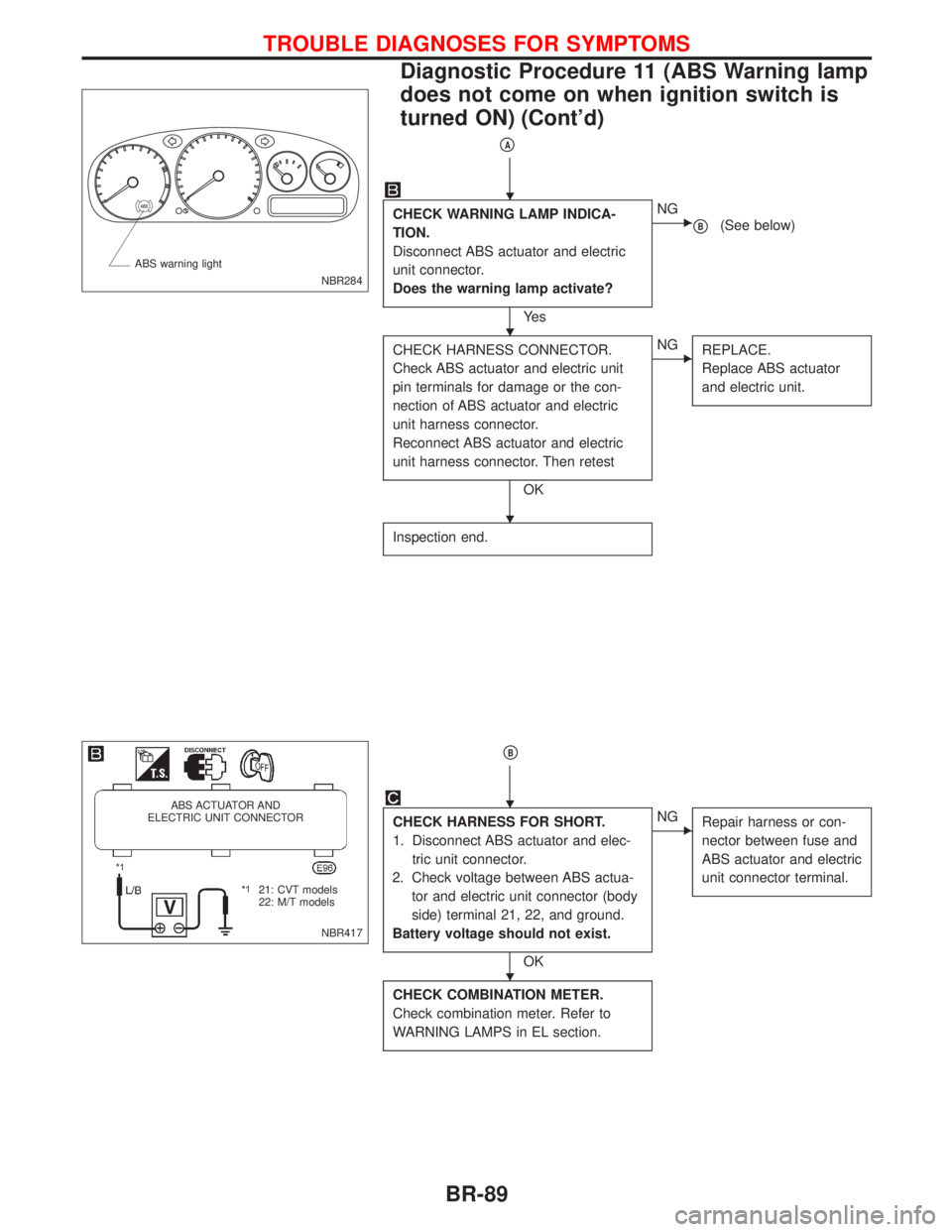
pA
CHECK WARNING LAMP INDICA-
TION.
Disconnect ABS actuator and electric
unit connector.
Does the warning lamp activate?
Ye s
ENG
pB(See below)
CHECK HARNESS CONNECTOR.
Check ABS actuator and electric unit
pin terminals for damage or the con-
nection of ABS actuator and electric
unit harness connector.
Reconnect ABS actuator and electric
unit harness connector. Then retest
OK
ENG
REPLACE.
Replace ABS actuator
and electric unit.
Inspection end.
pB
CHECK HARNESS FOR SHORT.
1. Disconnect ABS actuator and elec-
tric unit connector.
2. Check voltage between ABS actua-
tor and electric unit connector (body
side) terminal 21, 22, and ground.
Battery voltage should not exist.
OK
ENG
Repair harness or con-
nector between fuse and
ABS actuator and electric
unit connector terminal.
CHECK COMBINATION METER.
Check combination meter. Refer to
WARNING LAMPS in EL section.
NBR284 ABS warning light
NBR417
ABS ACTUATOR AND
ELECTRIC UNIT CONNECTOR
.21: CVT models
22: M/T models
H
H
H
H
H
TROUBLE DIAGNOSES FOR SYMPTOMS
Diagnostic Procedure 11 (ABS Warning lamp
does not come on when ignition switch is
turned ON) (Cont'd)
BR-89
Page 292 of 2267
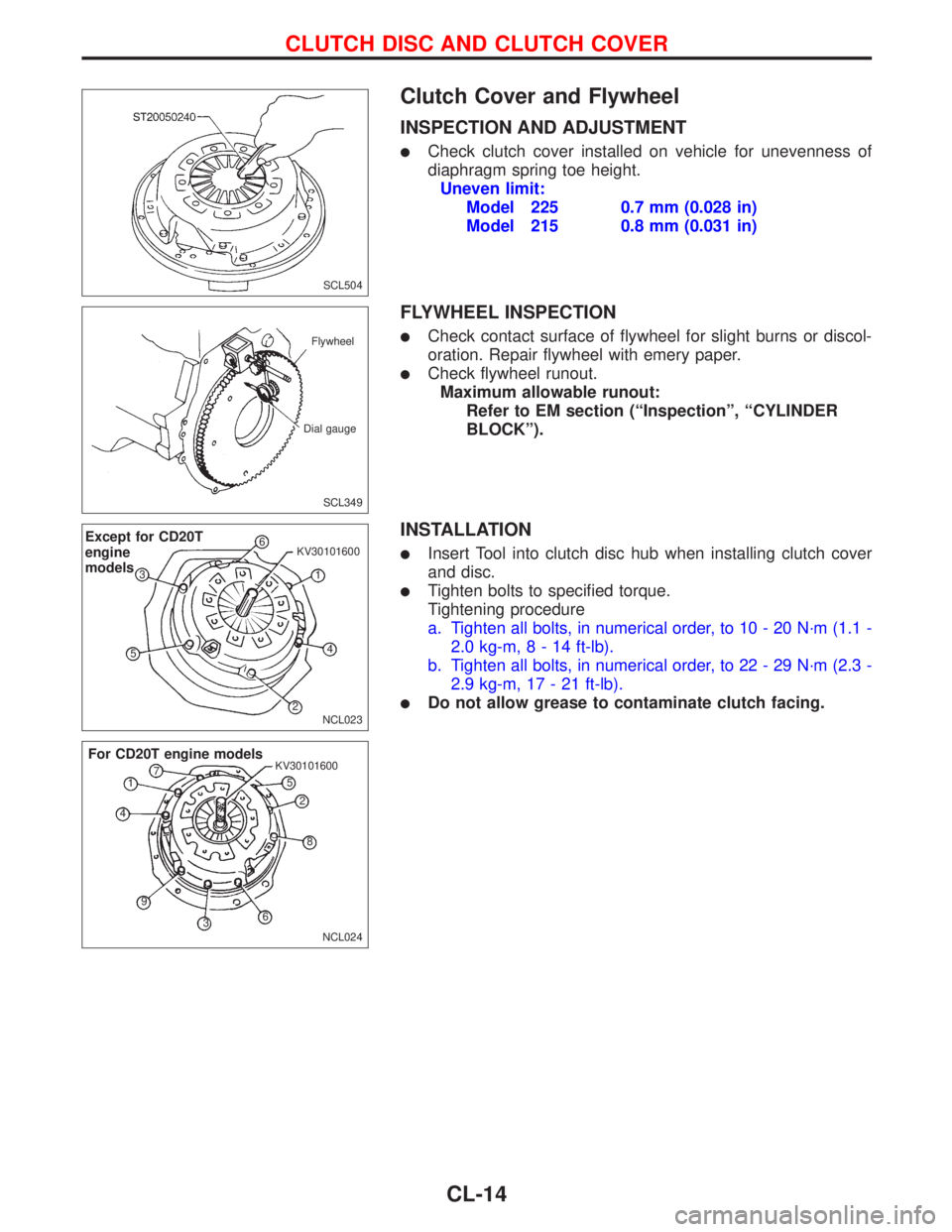
Clutch Cover and Flywheel
INSPECTION AND ADJUSTMENT
lCheck clutch cover installed on vehicle for unevenness of
diaphragm spring toe height.
Uneven limit:
Model 225 0.7 mm (0.028 in)
Model 215 0.8 mm (0.031 in)
FLYWHEEL INSPECTION
lCheck contact surface of flywheel for slight burns or discol-
oration. Repair flywheel with emery paper.
lCheck flywheel runout.
Maximum allowable runout:
Refer to EM section (ªInspectionº, ªCYLINDER
BLOCKº).
INSTALLATION
lInsert Tool into clutch disc hub when installing clutch cover
and disc.
lTighten bolts to specified torque.
Tightening procedure
a. Tighten all bolts, in numerical order, to 10 - 20 N´m (1.1 -
2.0 kg-m,8-14ft-lb).
b. Tighten all bolts, in numerical order, to 22 - 29 N´m (2.3 -
2.9 kg-m, 17 - 21 ft-lb).
lDo not allow grease to contaminate clutch facing.
SCL504
SCL349 Flywheel
Dial gauge
NCL023
Except for CD20T
engine
models6
1 KV30101600
4
2 53
NCL024 KV30101600
For CD20T engine models
1
2
3 45
6 7
8
9
CLUTCH DISC AND CLUTCH COVER
CL-14
Page 299 of 2267
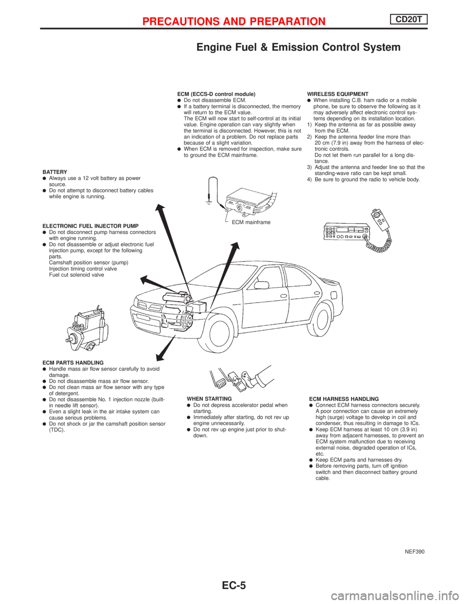
Engine Fuel & Emission Control System
NEF390 ECM (ECCS-D control module)
lDo not disassemble ECM.lIf a battery terminal is disconnected, the memory
will return to the ECM value.
The ECM will now start to self-control at its initial
value. Engine operation can vary slightly when
the terminal is disconnected. However, this is not
an indication of a problem. Do not replace parts
because of a slight variation.
lWhen ECM is removed for inspection, make sure
to ground the ECM mainframe.WIRELESS EQUIPMENT
lWhen installing C.B. ham radio or a mobile
phone, be sure to observe the following as it
may adversely affect electronic control sys-
tems depending on its installation location.
1) Keep the antenna as far as possible away
from the ECM.
2) Keep the antenna feeder line more than
20 cm (7.9 in) away from the harness of elec-
tronic controls.
Do not let them run parallel for a long dis-
tance.
3) Adjust the antenna and feeder line so that the
standing-wave ratio can be kept small.
4) Be sure to ground the radio to vehicle body.
ECM HARNESS HANDLING
lConnect ECM harness connectors securely.
A poor connection can cause an extremely
high (surge) voltage to develop in coil and
condenser, thus resulting in damage to ICs.
lKeep ECM harness at least 10 cm (3.9 in)
away from adjacent harnesses, to prevent an
ECM system malfunction due to receiving
external noise, degraded operation of ICs,
etc.
lKeep ECM parts and harnesses dry.lBefore removing parts, turn off ignition
switch and then disconnect battery ground
cable. WHEN STARTING
lDo not depress accelerator pedal when
starting.
lImmediately after starting, do not rev up
engine unnecessarily.
lDo not rev up engine just prior to shut-
down. ECM PARTS HANDLING
lHandle mass air flow sensor carefully to avoid
damage.
lDo not disassemble mass air flow sensor.lDo not clean mass air flow sensor with any type
of detergent.
lDo not disassemble No. 1 injection nozzle (built-
in needle lift sensor).
lEven a slight leak in the air intake system can
cause serious problems.
lDo not shock or jar the camshaft position sensor
(TDC). ELECTRONIC FUEL INJECTOR PUMP
lDo not disconnect pump harness connectors
with engine running.
lDo not disassemble or adjust electronic fuel
injection pump, except for the following
parts.
Camshaft position sensor (pump)
Injection timing control valve
Fuel cut solenoid valve BATTERY
lAlways use a 12 volt battery as power
source.
lDo not attempt to disconnect battery cables
while engine is running.
ECM mainframe
PRECAUTIONS AND PREPARATIONCD20T
EC-5
Page 300 of 2267
Supplemental Restraint System (SRS) ªAIR
BAGº and ªSEAT BELT PRE-TENSIONERº
NCEC0002
The Supplemental Restraint System ªAIR BAGº and ªSEAT BELT PRE-TENSIONERº, used along with a seat
belt, help to reduce the risk or severity of injury to the driver and front passenger in a frontal collision. The
Supplemental Restraint System consists of air bag modules (located in the center of the steering wheel and
on the instrument panel on the passenger side), seat belt pre-tensioners, a diagnosis sensor unit, warning
lamp, wiring harness and spiral cable.
In addition to the supplemental air bag modules for a frontal collision, the supplemental side air bag used
along with the seat belt helps to reduce the risk or severity of injury to the driver and front passenger in a
side collision. The supplemental side air bag consists of air bag modules (located in the outer side of front
seats), satellite sensor, diagnosis sensor unit (one of components of supplemental air bags for a frontal
collision), wiring harness, warning lamp (one of components of supplemental air bags for a frontal collision).
Information necessary to service the system safely is included in theRS sectionof this Service Manual.
WARNING:
lTo avoid rendering the SRS inoperative, which could increase the risk of personal injury or death
in the event of a collision which would result in air bag inflation, all maintenance must be per-
formed by an authorized NISSAN dealer.
lImproper maintenance, including incorrect removal and installation of the SRS, can lead to per-
sonal injury caused by unintentional activation of the system.
lDo not use electrical test equipment on any circuit related to the SRS unless instructed to in this
Service Manual. SRS wiring harnesses (except ªSEAT BELT PRE-TENSIONERº connector) can be
identified with yellow harness connector (and with yellow harness protector or yellow insulation
tape before the harness connectors).
Precautions for On Board Diagnostic (OBD)
System of Engine
NCEC0003
The ECM has an on board diagnostic system. It will light up the malfunction indicator (MI) to warn the driver
of a malfunction causing emission deterioration.
CAUTION:
lBe sure to turn the ignition switch ªOFFº and disconnect the negative battery terminal before any
repair or inspection work. The open/short circuit of related switches, sensors, solenoid valves,
etc. will cause the MI to light up.
lBe sure to connect and lock the connectors securely after work. A loose (unlocked) connector
will cause the MI to light up due to the open circuit. (Be sure the connector is free from water,
grease, dirt, bent terminals, etc.)
lCertain systems and components, especially those related to OBD, may use a new style slide-
locking type harness connector.
For description and how to disconnect, refer to EL section, ªDescriptionº, ªHARNESS CONNEC-
TORº.
lBe sure to route and secure the harnesses properly after work. The interference of the harness
with a bracket, etc. may cause the MI to light up due to the short circuit.
lBe sure to connect rubber tubes properly after work. A misconnected or disconnected rubber
tube may cause the MI to light up due to the malfunction of the EGR system or fuel injection
system, etc.
lBe sure to erase the unnecessary malfunction information (repairs completed) from the ECM
before returning the vehicle to the customer.
PRECAUTIONS AND PREPARATIONCD20T
EC-6
Page 329 of 2267
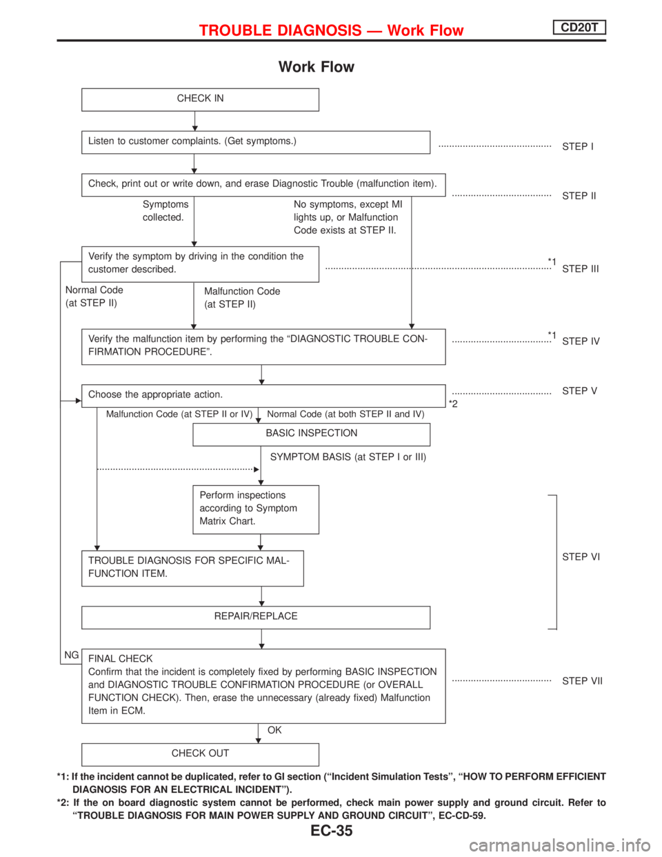
Work Flow
CHECK IN
Listen to customer complaints. (Get symptoms.)..........................................
STEP I
Check, print out or write down, and erase Diagnostic Trouble (malfunction item).
.....................................
STEP II
Symptoms
collected.No symptoms, except MI
lights up, or Malfunction
Code exists at STEP II.
Verify the symptom by driving in the condition the
customer described.
H
*1
....................................................................................
STEP III
Normal Code
(at STEP II)
Malfunction Code
(at STEP II)
Verify the malfunction item by performing the ªDIAGNOSTIC TROUBLE CON-
FIRMATION PROCEDUREº.
*1
.....................................
STEP IV
EChoose the appropriate action.
Malfunction Code (at STEP II or IV) Normal Code (at both STEP II and IV)
.....................................
*2STEP V
BASIC INSPECTION
SYMPTOM BASIS (at STEP I or III)
...........................................................
E
Perform inspections
according to Symptom
Matrix Chart.
H
TROUBLE DIAGNOSIS FOR SPECIFIC MAL-
FUNCTION ITEM.STEP VI
REPAIR/REPLACE
NGFINAL CHECK
Confirm that the incident is completely fixed by performing BASIC INSPECTION
and DIAGNOSTIC TROUBLE CONFIRMATION PROCEDURE (or OVERALL
FUNCTION CHECK). Then, erase the unnecessary (already fixed) Malfunction
Item in ECM.
OK.....................................
STEP VII
CHECK OUT
*1: If the incident cannot be duplicated, refer to GI section (ªIncident Simulation Testsº, ªHOW TO PERFORM EFFICIENT
DIAGNOSIS FOR AN ELECTRICAL INCIDENTº).
*2: If the on board diagnostic system cannot be performed, check main power supply and ground circuit. Refer to
ªTROUBLE DIAGNOSIS FOR MAIN POWER SUPPLY AND GROUND CIRCUITº, EC-CD-59.
H
H
H
H
H
H
H
H
H
H
H
TROUBLE DIAGNOSIS Ð Work FlowCD20T
EC-35
Page 334 of 2267
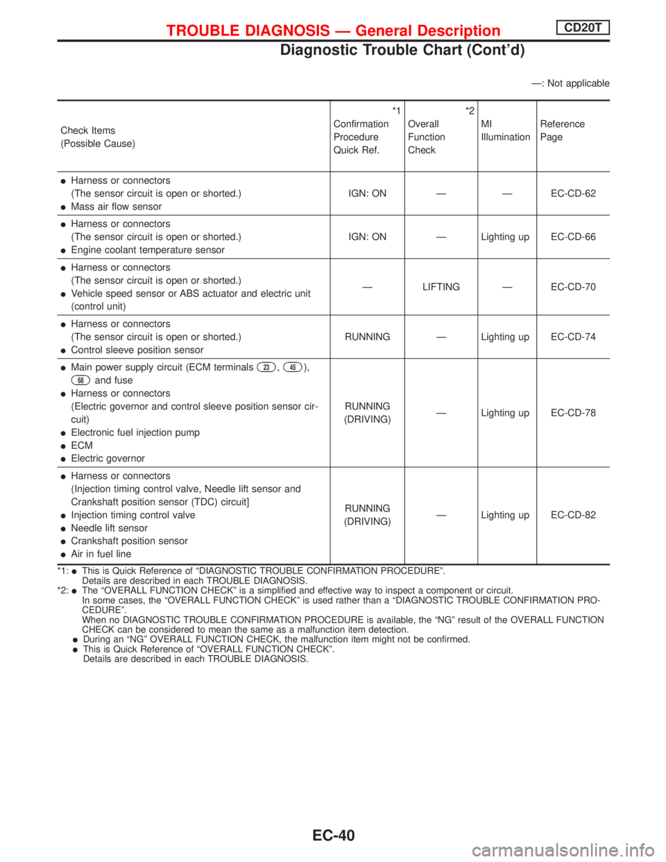
Ð: Not applicable
Check Items
(Possible Cause)*1
Confirmation
Procedure
Quick Ref.*2
Overall
Function
CheckMI
IlluminationReference
Page
lHarness or connectors
(The sensor circuit is open or shorted.)
lMass air flow sensorIGN: ON Ð Ð EC-CD-62
lHarness or connectors
(The sensor circuit is open or shorted.)
lEngine coolant temperature sensorIGN: ON Ð Lighting up EC-CD-66
lHarness or connectors
(The sensor circuit is open or shorted.)
lVehicle speed sensor or ABS actuator and electric unit
(control unit)Ð LIFTING Ð EC-CD-70
lHarness or connectors
(The sensor circuit is open or shorted.)
lControl sleeve position sensorRUNNING Ð Lighting up EC-CD-74
lMain power supply circuit (ECM terminals23,45),
68and fuse
lHarness or connectors
(Electric governor and control sleeve position sensor cir-
cuit)
lElectronic fuel injection pump
lECM
lElectric governorRUNNING
(DRIVING)Ð Lighting up EC-CD-78
lHarness or connectors
(Injection timing control valve, Needle lift sensor and
Crankshaft position sensor (TDC) circuit]
lInjection timing control valve
lNeedle lift sensor
lCrankshaft position sensor
lAir in fuel lineRUNNING
(DRIVING)Ð Lighting up EC-CD-82
*1:lThis is Quick Reference of ªDIAGNOSTIC TROUBLE CONFIRMATION PROCEDUREº.
Details are described in each TROUBLE DIAGNOSIS.
*2:
lThe ªOVERALL FUNCTION CHECKº is a simplified and effective way to inspect a component or circuit.
In some cases, the ªOVERALL FUNCTION CHECKº is used rather than a ªDIAGNOSTIC TROUBLE CONFIRMATION PRO-
CEDUREº.
When no DIAGNOSTIC TROUBLE CONFIRMATION PROCEDURE is available, the ªNGº result of the OVERALL FUNCTION
CHECK can be considered to mean the same as a malfunction item detection.
lDuring an ªNGº OVERALL FUNCTION CHECK, the malfunction item might not be confirmed.lThis is Quick Reference of ªOVERALL FUNCTION CHECKº.
Details are described in each TROUBLE DIAGNOSIS.
TROUBLE DIAGNOSIS Ð General DescriptionCD20T
Diagnostic Trouble Chart (Cont'd)
EC-40