1999 NISSAN PRIMERA light
[x] Cancel search: lightPage 336 of 2267
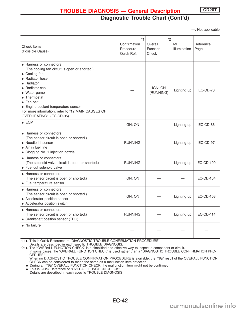
Ð: Not applicable
Check Items
(Possible Cause)*1
Confirmation
Procedure
Quick Ref.*2
Overall
Function
CheckMI
IlluminationReference
Page
lHarness or connectors
(The cooling fan circuit is open or shorted.)
lCooling fan
lRadiator hose
lRadiator
lRadiator cap
lWater pump
lThermostat
lFan belt
lEngine coolant temperature sensor
For more information, refer to ª12 MAIN CAUSES OF
OVERHEATINGº. (EC-CD-95)ÐIGN: ON
(RUNNING)Lighting up EC-CD-78
lECM
IGN: ON Ð Lighting up EC-CD-86
lHarness or connectors
(The sensor circuit is open or shorted.)
lNeedle lift sensor
lAir in fuel line
lClogging No. 1 injection nozzleRUNNING Ð Lighting up EC-CD-97
lHarness or connectors
(The solenoid valve circuit is open or shorted.)
lFuel cut solenoid valveRUNNING Ð Lighting up EC-CD-100
lHarness or connectors
(The sensor circuit is open or shorted.)
lFuel temperature sensorIGN: ON Ð Ð EC-CD-104
lHarness or connectors
(The sensor circuit is open or shorted.)
lAccelerator position sensor
lAccelerator position switchIGN: ON Ð Lighting up EC-CD-108
lHarness or connectors
(The sensor circuit is open or shorted.)
lCrankshaft position sensor (TDC)RUNNING Ð Lighting up EC-CD-114
lNo failure
Ð ÐÐÐ
*1:lThis is Quick Reference of ªDIAGNOSTIC TROUBLE CONFIRMATION PROCEDUREº.
Details are described in each specific TROUBLE DIAGNOSIS.
*2:
lThe ªOVERALL FUNCTION CHECKº is a simplified and effective way to inspect a component or circuit.
In some cases, the ªOVERALL FUNCTION CHECKº is used rather than a ªDIAGNOSTIC TROUBLE CONFIRMATION PRO-
CEDUREº.
When no DIAGNOSTIC TROUBLE CONFIRMATION PROCEDURE is available, the ªNGº result of the OVERALL FUNCTION
CHECK can be considered to mean the same as a malfunction item detection.
lDuring an ªNGº OVERALL FUNCTION CHECK, the malfunction item might not be confirmed.lThis is Quick Reference of ªOVERALL FUNCTION CHECKº.
Details are described in each specific TROUBLE DIAGNOSIS.
TROUBLE DIAGNOSIS Ð General DescriptionCD20T
Diagnostic Trouble Chart (Cont'd)
EC-42
Page 338 of 2267
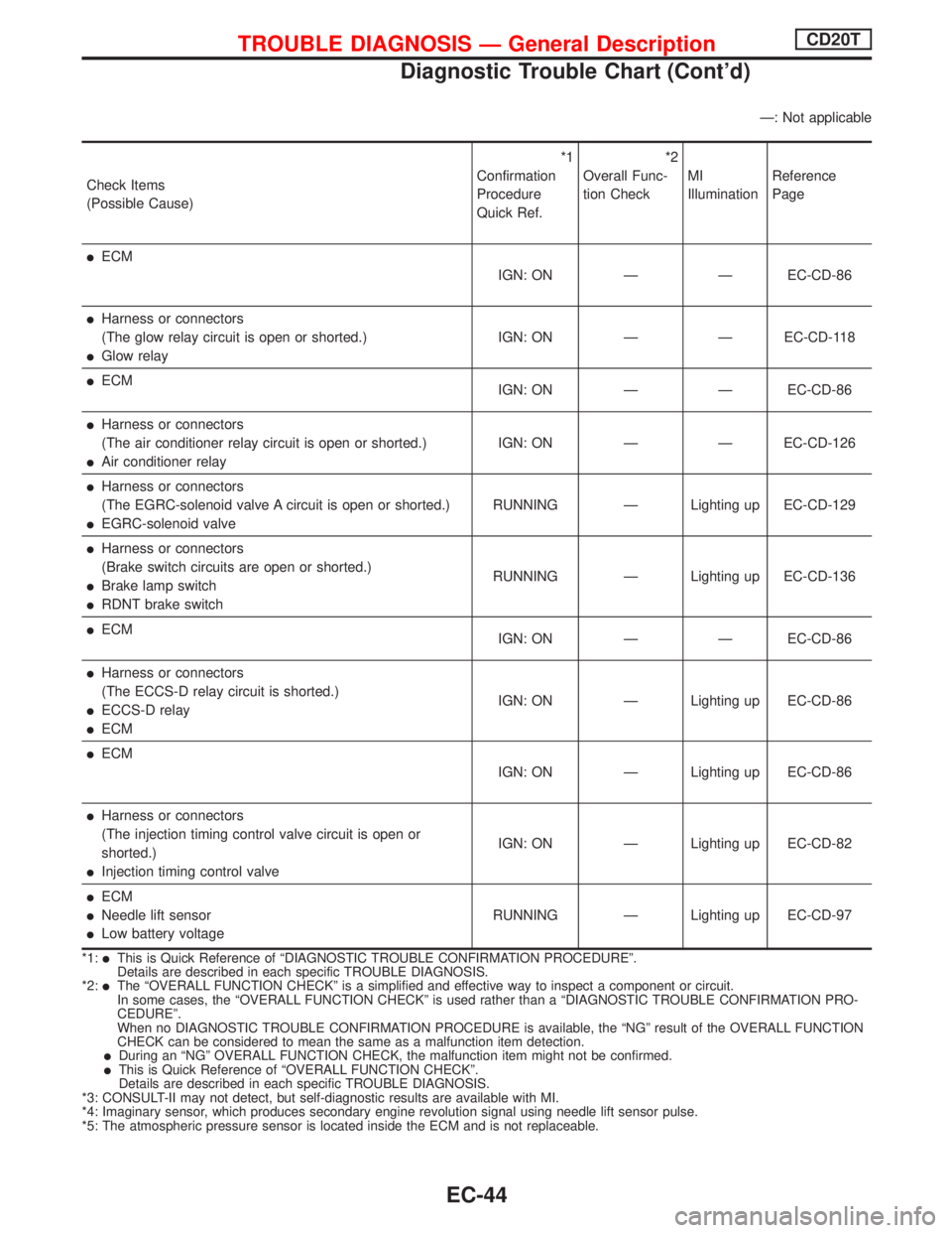
Ð: Not applicable
Check Items
(Possible Cause)*1
Confirmation
Procedure
Quick Ref.*2
Overall Func-
tion CheckMI
IlluminationReference
Page
lECM
IGN: ON Ð Ð EC-CD-86
lHarness or connectors
(The glow relay circuit is open or shorted.)
lGlow relayIGN: ON Ð Ð EC-CD-118
lECM
IGN: ON Ð Ð EC-CD-86
lHarness or connectors
(The air conditioner relay circuit is open or shorted.)
lAir conditioner relayIGN: ON Ð Ð EC-CD-126
lHarness or connectors
(The EGRC-solenoid valve A circuit is open or shorted.)
lEGRC-solenoid valveRUNNING Ð Lighting up EC-CD-129
lHarness or connectors
(Brake switch circuits are open or shorted.)
lBrake lamp switch
lRDNT brake switchRUNNING Ð Lighting up EC-CD-136
lECM
IGN: ON Ð Ð EC-CD-86
lHarness or connectors
(The ECCS-D relay circuit is shorted.)
lECCS-D relay
lECMIGN: ON Ð Lighting up EC-CD-86
lECM
IGN: ON Ð Lighting up EC-CD-86
lHarness or connectors
(The injection timing control valve circuit is open or
shorted.)
lInjection timing control valveIGN: ON Ð Lighting up EC-CD-82
lECM
lNeedle lift sensor
lLow battery voltageRUNNING Ð Lighting up EC-CD-97
*1:lThis is Quick Reference of ªDIAGNOSTIC TROUBLE CONFIRMATION PROCEDUREº.
Details are described in each specific TROUBLE DIAGNOSIS.
*2:
lThe ªOVERALL FUNCTION CHECKº is a simplified and effective way to inspect a component or circuit.
In some cases, the ªOVERALL FUNCTION CHECKº is used rather than a ªDIAGNOSTIC TROUBLE CONFIRMATION PRO-
CEDUREº.
When no DIAGNOSTIC TROUBLE CONFIRMATION PROCEDURE is available, the ªNGº result of the OVERALL FUNCTION
CHECK can be considered to mean the same as a malfunction item detection.
lDuring an ªNGº OVERALL FUNCTION CHECK, the malfunction item might not be confirmed.lThis is Quick Reference of ªOVERALL FUNCTION CHECKº.
Details are described in each specific TROUBLE DIAGNOSIS.
*3: CONSULT-II may not detect, but self-diagnostic results are available with MI.
*4: Imaginary sensor, which produces secondary engine revolution signal using needle lift sensor pulse.
*5: The atmospheric pressure sensor is located inside the ECM and is not replaceable.
TROUBLE DIAGNOSIS Ð General DescriptionCD20T
Diagnostic Trouble Chart (Cont'd)
EC-44
Page 344 of 2267
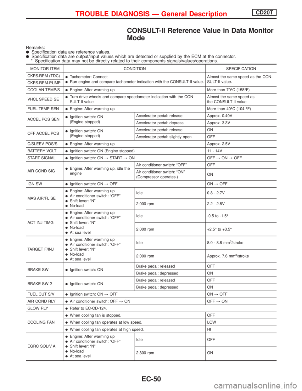
CONSULT-II Reference Value in Data Monitor
Mode
Remarks:lSpecification data are reference values.lSpecification data are output/input values which are detected or supplied by the ECM at the connector.
* Specification data may not be directly related to their components signals/values/operations.
MONITOR ITEM CONDITION SPECIFICATION
CKPS×RPM (TDC)
lTachometer: ConnectlRun engine and compare tachometer indication with the CONSULT-II value.Almost the same speed as the CON-
SULT-II value.
CKPS×RPM-PUMP
COOLAN TEMP/S
lEngine: After warming up More than 70ÉC (158ÉF)
VHCL SPEED SE
lTurn drive wheels and compare speedometer indication with the CON-
SULT-II valueAlmost the same speed as
the CONSULT-II value
FUEL TEMP SEN
lEngine: After warming up More than 40ÉC (104 ÉF)
ACCEL POS SEN
lIgnition switch: ON
(Engine stopped)Accelerator pedal: release Approx. 0.40V
Accelerator pedal: depress Approx. 3.3V
OFF ACCEL POS
lIgnition switch: ON
(Engine stopped)Accelerator pedal: release ON
Accelerator pedal: slightly open OFF
C/SLEEV POS/S
lEngine: After warming up Approx. 2.5V
BATTERY VOLT
lIgnition switch: ON (Engine stopped) 11 - 14V
START SIGNAL
lIgnition switch: ON,START,ON OFF,ON,OFF
AIR COND SIG
lEngine: After warming up, idle the
engineAir conditioner switch: ªOFFº OFF
Air conditioner switch: ªONº
(Compressor operates.)ON
IGN SW
lIgnition switch: ON,OFF ON,OFF
MAS AIR/FL SE
lEngine: After warming uplAir conditioner switch: ªOFFºlShift lever: ªNºlNo-loadIdle 0.8 - 2.7V
2,000 rpm 2.2 - 2.8V
ACT INJ TIMG
lEngine: After warming uplAir conditioner switch: ªOFFºlShift lever: ªNºlNo-loadlAt sea levelIdle -0.5 to -1.5É
2,000 rpm +2.5É to +3.5É
TARGET F/INJ
lEngine: After warming uplAir conditioner switch: ªOFFºlShift lever: ªNºlNo-loadlAt sea levelIdle 8.0 - 8.8 mm
3/stroke
2,000 rpm Approx. 7.6 mm
3/stroke
BRAKE SW
lIgnition switch: ONBrake pedal: released OFF
Brake pedal: depressed ON
BRAKE SW 2
lIgnition switch: ONBrake pedal: released OFF
Brake pedal: depressed ON
FUEL CUT S/V
lIgnition switch: ON,OFF ON,OFF
AIR COND RLY
lAir conditioner switch: OFF,ON OFF,ON
GLOW RLY
lRefer to EC-CD-124.
COOLING FAN
lWhen cooling fan is stopped. OFF
lWhen cooling fan operates at low speed. LOW
lWhen cooling fan operates at high speed. HI
EGRC SOL/V A
lEngine: After warming uplAir conditioner switch: ªOFFºlShift lever: ªNºlNo-loadlAt sea levelIdle OFF
2,800 rpm ON
TROUBLE DIAGNOSIS Ð General DescriptionCD20T
EC-50
Page 451 of 2267
Supplemental Restraint System (SRS) ªAIR
BAGº and ªSEAT BELT PRE-TENSIONERº
NCEC0002The Supplemental Restraint System ªAIR BAGº and ªSEAT BELT PRE-TENSIONERº, used along with a seat
belt, help to reduce the risk or severity of injury to the driver and front passenger in a frontal collision. The
Supplemental Restraint System consists of air bag modules (located in the center of the steering wheel and
on the instrument panel on the passenger side), seat belt pre-tensioners, a diagnosis sensor unit, warning
lamp, wiring harness and spiral cable.
In addition to the supplemental air bag modules for a frontal collision, the supplemental side air bag used along
with the seat belt helps to reduce the risk or severity of injury to the driver and front passenger in a side col-
lision. The supplemental side air bag consists of air bag modules (located in the outer side of front seats),
satellite sensor, diagnosis sensor unit (one of components of supplemental air bags for a frontal collision),
wiring harness, warning lamp (one of components of supplemental air bags for a frontal collision). Information
necessary to service the system safely is included in theRS sectionof this Service Manual.
WARNING:
ITo avoid rendering the SRS inoperative, which could increase the risk of personal injury or death
in the event of a collision which would result in air bag inflation, all maintenance must be performed
by an authorized NISSAN dealer.
IImproper maintenance, including incorrect removal and installation of the SRS, can lead to per-
sonal injury caused by unintentional activation of the system.
IDo not use electrical test equipment on any circuit related to the SRS unless instructed to in this
Service Manual. SRS wiring harnesses (except ªSEAT BELT PRE-TENSIONERº connector) can be
identified with yellow harness connector (and with yellow harness protector or yellow insulation
tape before the harness connectors).
Precautions for On Board Diagnostic (OBD)
System of Engine
NCEC0003The ECM has an on board diagnostic system. It will light up the malfunction indicator (MI) to warn the driver
of a malfunction causing emission deterioration.
CAUTION:
IBe sure to turn the ignition switch ªOFFº and disconnect the negative battery terminal before any
repair or inspection work. The open/short circuit of related switches, sensors, solenoid valves, etc.
will cause the MI to light up.
IBe sure to connect and lock the connectors securely after work. A loose (unlocked) connector will
cause the MI to light up due to the open circuit. (Be sure the connector is free from water, grease,
dirt, bent terminals, etc.)
ICertain systems and components, especially those related to OBD, may use a new style slide-
locking type harness connector.
For description and how to disconnect, refer to EL section, ªDescriptionº, ªHARNESS CONNEC-
TORº.
IBe sure to route and secure the harnesses properly after work. The interference of the harness with
a bracket, etc. may cause the MI to light up due to the short circuit.
IBe sure to connect rubber tubes properly after work. A misconnected or disconnected rubber tube
may cause the MI to light up due to the malfunction of the EGR system or fuel injection system,
etc.
IBe sure to erase the unnecessary malfunction information (repairs completed) from the ECM before
returning the vehicle to the customer.
PRECAUTIONSQG16I18DE
Supplemental Restraint System (SRS) ªAIR BAGº and ªSEAT BELT PRE-TENSIONERº
EC-9
Page 474 of 2267
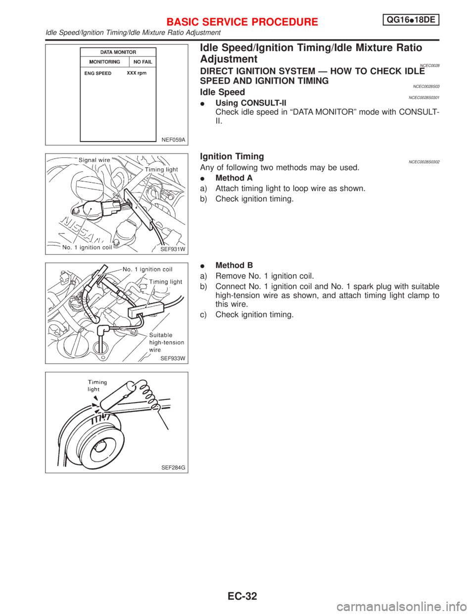
Idle Speed/Ignition Timing/Idle Mixture Ratio
Adjustment
NCEC0028DIRECT IGNITION SYSTEM Ð HOW TO CHECK IDLE
SPEED AND IGNITION TIMING
NCEC0028S03Idle SpeedNCEC0028S0301IUsing CONSULT-II
Check idle speed in ªDATA MONITORº mode with CONSULT-
II.
Ignition TimingNCEC0028S0302Any of following two methods may be used.
IMethod A
a) Attach timing light to loop wire as shown.
b) Check ignition timing.
IMethod B
a) Remove No. 1 ignition coil.
b) Connect No. 1 ignition coil and No. 1 spark plug with suitable
high-tension wire as shown, and attach timing light clamp to
this wire.
c) Check ignition timing.
NEF059A
SEF931W
SEF933W
SEF284G
BASIC SERVICE PROCEDUREQG16I18DE
Idle Speed/Ignition Timing/Idle Mixture Ratio Adjustment
EC-32
Page 475 of 2267
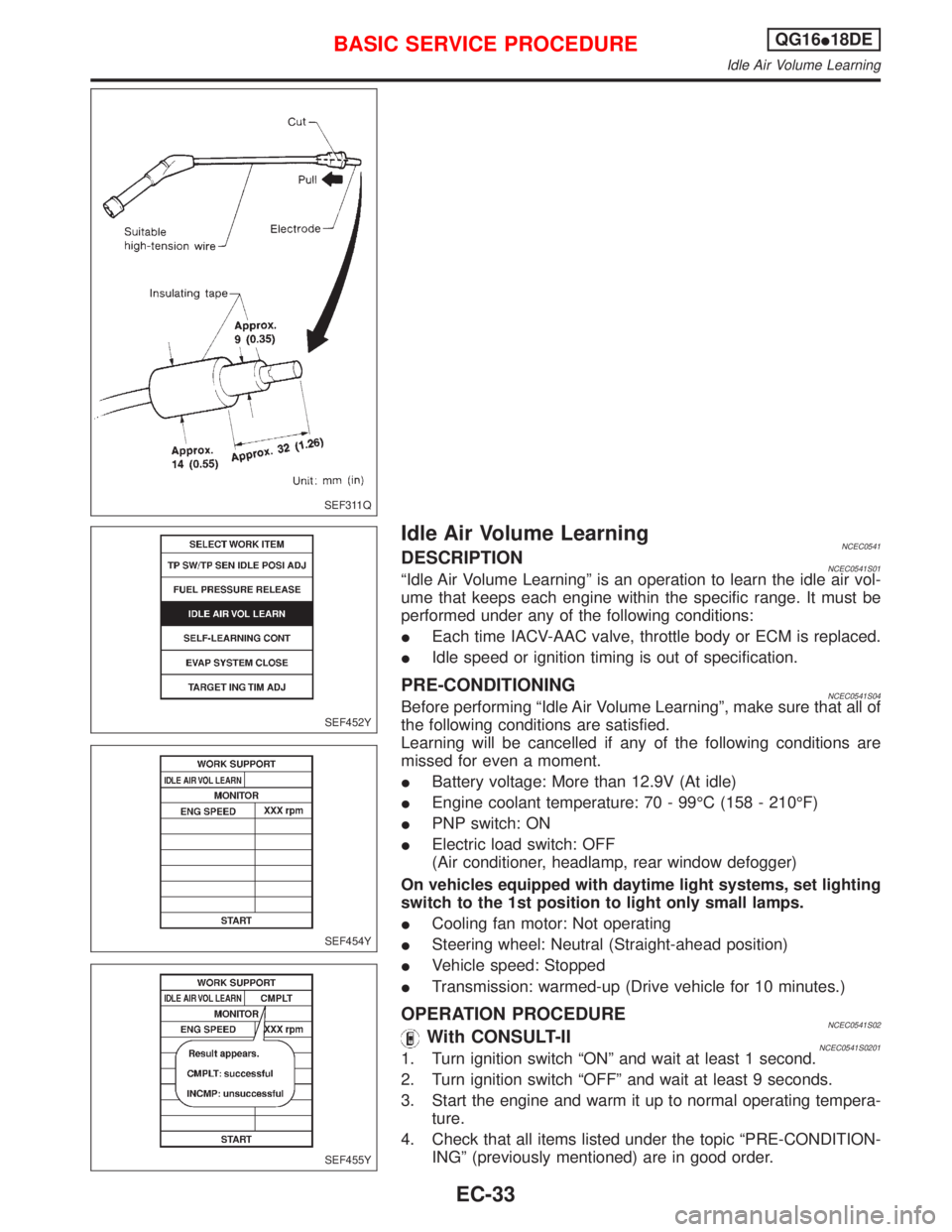
Idle Air Volume LearningNCEC0541DESCRIPTIONNCEC0541S01ªIdle Air Volume Learningº is an operation to learn the idle air vol-
ume that keeps each engine within the specific range. It must be
performed under any of the following conditions:
IEach time IACV-AAC valve, throttle body or ECM is replaced.
IIdle speed or ignition timing is out of specification.
PRE-CONDITIONINGNCEC0541S04Before performing ªIdle Air Volume Learningº, make sure that all of
the following conditions are satisfied.
Learning will be cancelled if any of the following conditions are
missed for even a moment.
IBattery voltage: More than 12.9V (At idle)
IEngine coolant temperature: 70 - 99ÉC (158 - 210ÉF)
IPNP switch: ON
IElectric load switch: OFF
(Air conditioner, headlamp, rear window defogger)
On vehicles equipped with daytime light systems, set lighting
switch to the 1st position to light only small lamps.
ICooling fan motor: Not operating
ISteering wheel: Neutral (Straight-ahead position)
IVehicle speed: Stopped
ITransmission: warmed-up (Drive vehicle for 10 minutes.)
OPERATION PROCEDURENCEC0541S02With CONSULT-IINCEC0541S02011. Turn ignition switch ªONº and wait at least 1 second.
2. Turn ignition switch ªOFFº and wait at least 9 seconds.
3. Start the engine and warm it up to normal operating tempera-
ture.
4. Check that all items listed under the topic ªPRE-CONDITION-
INGº (previously mentioned) are in good order.
SEF311Q
SEF452Y
SEF454Y
SEF455Y
BASIC SERVICE PROCEDUREQG16I18DE
Idle Air Volume Learning
EC-33
Page 478 of 2267
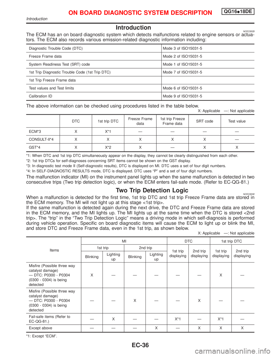
IntroductionNCEC0029The ECM has an on board diagnostic system which detects malfunctions related to engine sensors or actua-
tors. The ECM also records various emission-related diagnostic information including:
Diagnostic Trouble Code (DTC) Mode 3 of ISO15031-5
Freeze Frame data Mode 2 of ISO15031-5
System Readiness Test (SRT) code Mode 1 of ISO15031-5
1st Trip Diagnostic Trouble Code (1st Trip DTC) Mode 7 of ISO15031-5
1st Trip Freeze Frame data
Test values and Test limits Mode 6 of ISO15031-5
Calibration ID Mode 9 of ISO15031-5
The above information can be checked using procedures listed in the table below.
X: Applicable Ð: Not applicable
DTC 1st trip DTCFreeze Frame
data1st trip Freeze
Frame dataSRT code Test value
ECM*3 X X*1ÐÐÐÐ
CONSULT-II*4XXXXXÐ
GST*4 X X*2 X Ð X X
*1: When DTC and 1st trip DTC simultaneously appear on the display, they cannot be clearly distinguished from each other.
*2: 1st trip DTCs for self-diagnoses concerning SRT items cannot be shown on the GST display.
*3: In diagnostic test mode II (Self-diagnostic results), DTC is displayed on MI. DTC uses a set of four digit numbers.
*4: In SELF-DIAGNOSTIC RESULTS mode, DTC is displayed. DTC uses ªPº and a set of four digit numbers.
The malfunction indicator (MI) on the instrument panel lights up when the same malfunction is detected in two
consecutive trips (Two trip detection logic), or when the ECM enters fail-safe mode. (Refer to EC-QG-81.)
Two Trip Detection LogicNCEC0030When a malfunction is detected for the first time, 1st trip DTC and 1st trip Freeze Frame data are stored in
the ECM memory. The MI will not light up at this stage <1st trip>.
If the same malfunction is detected again during the next drive, the DTC and Freeze Frame data are stored
in the ECM memory, and the MI lights up. The MI lights up at the same time when the DTC is stored <2nd
trip>. The ªtripº in the ªTwo Trip Detection Logicº means a driving mode in which self-diagnosis is performed
during vehicle operation. Specific on board diagnostic items will cause the ECM to light up or blink the MI,
and store DTC and Freeze Frame data, even in the 1st trip, as shown below.
X: Applicable Ð: Not applicable
ItemsMI DTC 1st trip DTC
1st trip 2nd trip
1st trip
displaying2nd trip
displaying1st trip
displaying2nd trip
displaying
BlinkingLighting
upBlinkingLighting
up
Misfire (Possible three way
catalyst damage)
Ð DTC: P0300 - P0304
(0300 - 0304) is being
detectedX ÐÐÐÐÐ X Ð
Misfire (Possible three way
catalyst damage)
Ð DTC: P0300 - P0304
(0300 - 0304) is being
detectedÐÐXÐÐXÐÐ
Fail-safe items (Refer to
EC-QG-81.)Ð X Ð Ð X*1 Ð X*1 Ð
Except above Ð ÐÐXÐX X X
*1: Except ªECMº.
ON BOARD DIAGNOSTIC SYSTEM DESCRIPTIONQG16I18DE
Introduction
EC-36
Page 479 of 2267
Emission-related Diagnostic InformationNCEC0031DTC AND 1ST TRIP DTCNCEC0031S01The 1st trip DTC (whose number is the same as the DTC number) is displayed for the latest self-diagnostic
result obtained. If the ECM memory was cleared previously, and the 1st trip DTC did not reoccur, the 1st trip
DTC will not be displayed. If a malfunction is detected during the 1st trip, the 1st trip DTC is stored in the ECM
memory. The MI will not light up (two trip detection logic). If the same malfunction is not detected in the 2nd
trip (meeting the required driving pattern), the 1st trip DTC is cleared from the ECM memory. If the same mal-
function is detected in the 2nd trip, both the 1st trip DTC and DTC are stored in the ECM memory and the MI
lights up. In other words, the DTC is stored in the ECM memory and the MI lights up when the same malfunc-
tion occurs in two consecutive trips. If a 1st trip DTC is stored and a non-diagnostic operation is performed
between the 1st and 2nd trips, only the 1st trip DTC will continue to be stored. For malfunctions that blink or
light up the MI during the 1st trip, the DTC and 1st trip DTC are stored in the ECM memory.
Procedures for clearing the DTC and the 1st trip DTC from the ECM memory are described in ªHOW TO
ERASE EMISSION-RELATED DIAGNOSTIC INFORMATIONº. Refer to EC-QG-44.
For malfunctions in which 1st trip DTCs are displayed, refer to EC-QG-42. These items are required by legal
regulations to continuously monitor the system/component. In addition, the items monitored non-continuously
are also displayed on CONSULT-II.
1st trip DTC is specified in Mode 7 of ISO15031-5. 1st trip DTC detection occurs without lighting up the MI
and therefore does not warn the driver of a problem. However, 1st trip DTC detection will not prevent the
vehicle from being tested, for example during Inspection/Maintenance (I/M) tests.
When a 1st trip DTC is detected, check, print out or write down and erase (1st trip) DTC and Freeze Frame
data as specified in ªWork Flowº procedure Step II, refer to page EC-QG-70. Then perform ªDTC Confirma-
tion Procedureº or ªOverall Function Checkº to try to duplicate the problem. If the malfunction is duplicated,
the item requires repair.
How to read DTC and 1st Trip DTCNCEC0031S0101DTC and 1st trip DTC can be read by the following methods.
1)
No Tools
The number of blinks of MI in the Diagnostic Test Mode II (Self-Diagnostic Results) Examples: 0340, 1320,
0705, 0750, etc.
These DTCs are controlled by NISSAN.
2)
With CONSULT-II
With GST
CONSULT-II or GST (Generic Scan Tool) Examples: P0340, P1320, P0705, P0750, etc.
These DTCs are prescribed by ISO15031-6.
(CONSULT-II also displays the malfunctioning component or system.)
I1st trip DTC No. is the same as DTC No.
IOutput of a DTC indicates a malfunction. However, Mode II and GST do not indicate whether the
malfunction is still occurring or has occurred in the past and has returned to normal.
CONSULT-II can identify malfunction status as shown below. Therefore, using CONSULT-II (if avail-
able) is recommended.
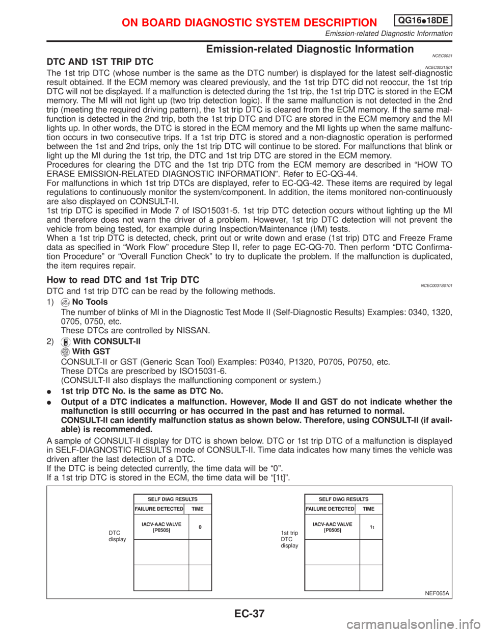
A sample of CONSULT-II display for DTC is shown below. DTC or 1st trip DTC of a malfunction is displayed
in SELF-DIAGNOSTIC RESULTS mode of CONSULT-II. Time data indicates how many times the vehicle was
driven after the last detection of a DTC.
If the DTC is being detected currently, the time data will be ª0º.
If a 1st trip DTC is stored in the ECM, the time data will be ª[1t]º.
NEF065A DTC
display1st trip
DTC
display
ON BOARD DIAGNOSTIC SYSTEM DESCRIPTIONQG16I18DE
Emission-related Diagnostic Information
EC-37