1999 DODGE NEON cooling
[x] Cancel search: coolingPage 787 of 1200
TIMING BELT COVER
REMOVAL
CAUTION: Camshaft or crankshaft should not be
rotated after timing belt is removed. Damage to
valve components may occur. Always align timing
marks before removing timing belt.
(1) Remove accessory drive belts. Refer to Group 7,
Cooling System for procedure outlined in that sec-
tion.
(2) Raise vehicle on a hoist and remove right inner
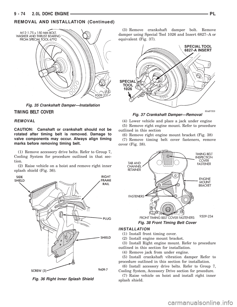
splash shield (Fig. 36).(3) Remove crankshaft damper bolt. Remove
damper using Special Tool 1026 and Insert 6827±A or
equivalent (Fig. 37).
(4) Lower vehicle and place a jack under engine
(5) Remove right engine mount. Refer to procedure
outlined in this section
(6) Remove right engine mount bracket (Fig. 38)
(7) Remove timing belt cover fasteners, remove
cover (Fig. 38).
INSTALLATION
(1) Install front timing cover.
(2) Install engine mount bracket.
(3) Install Right engine mount. Refer to procedure
outlined in this section for installation.
(4) Remove jack from under engine.
(5) Install crankshaft vibration damper Refer to
procedure outlined in this section for installation.
(6)
Install accessory drive belts. Refer to Group 7,
Cooling System, Accessory Drive section for procedure.
(7) Raise vehicle on hoist and install right inner
splash shield.
Fig. 35 Crankshaft DamperÐInstallation
Fig. 36 Right Inner Splash Shield
Fig. 37 Crankshaft DamperÐRemoval
Fig. 38 Front Timing Belt Cover
9 - 74 2.0L DOHC ENGINEPL
REMOVAL AND INSTALLATION (Continued)
Page 788 of 1200
TIMING BELTÐWITH HYDRAULIC TENSIONER
CHECKING BELT TIMINGÐCOVER INSTALLED
(1) Remove number one spark plug.
(2) Using a dial indicator, set number one cylinder
to TDC on the compression stroke.
(3) Remove the timing belt access cover from the
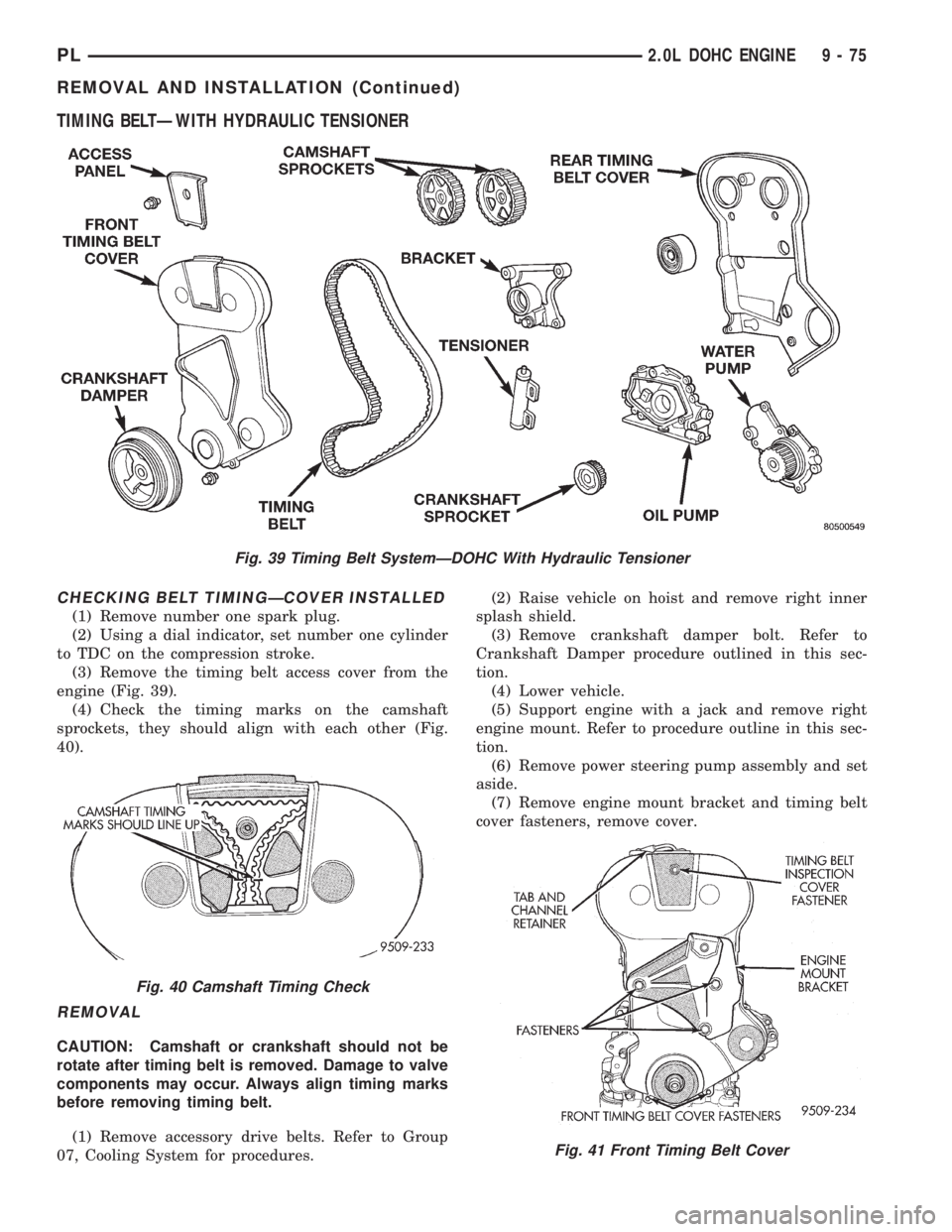
engine (Fig. 39).
(4) Check the timing marks on the camshaft
sprockets, they should align with each other (Fig.
40).
REMOVAL
CAUTION: Camshaft or crankshaft should not be
rotate after timing belt is removed. Damage to valve
components may occur. Always align timing marks
before removing timing belt.
(1) Remove accessory drive belts. Refer to Group
07, Cooling System for procedures.(2) Raise vehicle on hoist and remove right inner
splash shield.
(3) Remove crankshaft damper bolt. Refer to
Crankshaft Damper procedure outlined in this sec-
tion.
(4) Lower vehicle.
(5) Support engine with a jack and remove right
engine mount. Refer to procedure outline in this sec-
tion.
(6) Remove power steering pump assembly and set
aside.
(7) Remove engine mount bracket and timing belt
cover fasteners, remove cover.
Fig. 39 Timing Belt SystemÐDOHC With Hydraulic Tensioner
Fig. 40 Camshaft Timing Check
Fig. 41 Front Timing Belt Cover
PL2.0L DOHC ENGINE 9 - 75
REMOVAL AND INSTALLATION (Continued)
Page 790 of 1200
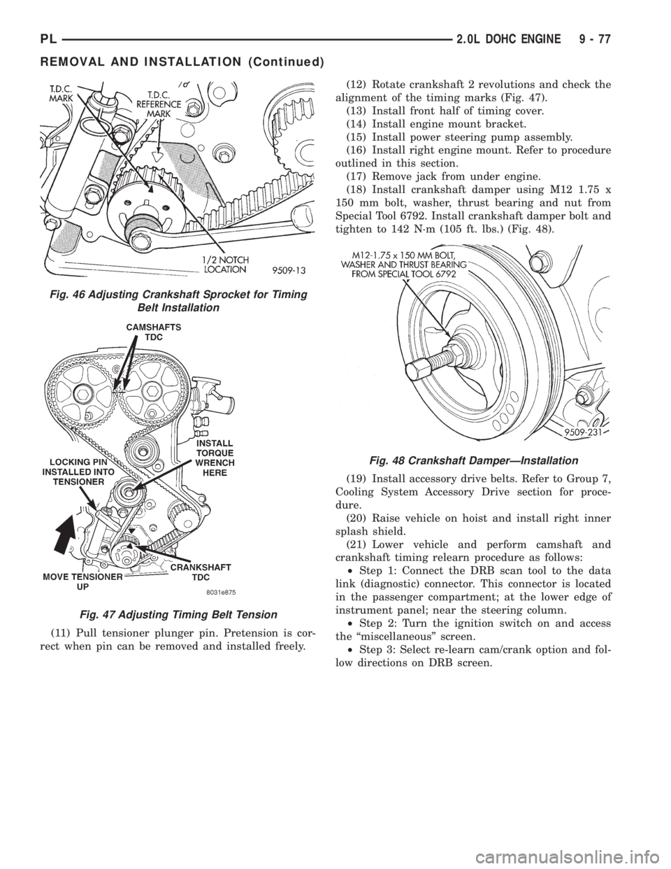
(11) Pull tensioner plunger pin. Pretension is cor-
rect when pin can be removed and installed freely.(12) Rotate crankshaft 2 revolutions and check the
alignment of the timing marks (Fig. 47).
(13) Install front half of timing cover.
(14) Install engine mount bracket.
(15) Install power steering pump assembly.
(16) Install right engine mount. Refer to procedure
outlined in this section.
(17) Remove jack from under engine.
(18) Install crankshaft damper using M12 1.75 x
150 mm bolt, washer, thrust bearing and nut from
Special Tool 6792. Install crankshaft damper bolt and
tighten to 142 N´m (105 ft. lbs.) (Fig. 48).
(19) Install accessory drive belts. Refer to Group 7,
Cooling System Accessory Drive section for proce-
dure.
(20) Raise vehicle on hoist and install right inner
splash shield.
(21) Lower vehicle and perform camshaft and
crankshaft timing relearn procedure as follows:
²Step 1: Connect the DRB scan tool to the data
link (diagnostic) connector. This connector is located
in the passenger compartment; at the lower edge of
instrument panel; near the steering column.
²Step 2: Turn the ignition switch on and access
the ªmiscellaneousº screen.
²Step 3: Select re-learn cam/crank option and fol-
low directions on DRB screen.
Fig. 46 Adjusting Crankshaft Sprocket for Timing
Belt Installation
Fig. 47 Adjusting Timing Belt Tension
Fig. 48 Crankshaft DamperÐInstallation
PL2.0L DOHC ENGINE 9 - 77
REMOVAL AND INSTALLATION (Continued)
Page 791 of 1200
TIMING BELTÐWITH MECHANICAL TENSIONER
CHECKING BELT TIMINGÐCOVER INSTALLED
(1) Remove number one spark plug.
(2) Using a dial indicator, set number one cylinder
to TDC on the compression stroke.
(3) Remove the timing belt access cover from the
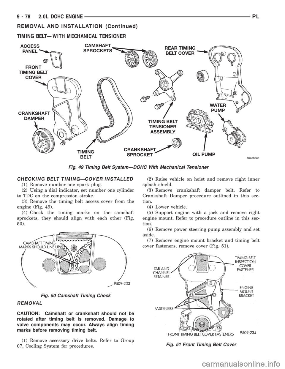
engine (Fig. 49).
(4) Check the timing marks on the camshaft
sprockets, they should align with each other (Fig.
50).
REMOVAL
CAUTION: Camshaft or crankshaft should not be
rotated after timing belt is removed. Damage to
valve components may occur. Always align timing
marks before removing timing belt.
(1) Remove accessory drive belts. Refer to Group
07, Cooling System for procedures.(2) Raise vehicle on hoist and remove right inner
splash shield.
(3) Remove crankshaft damper bolt. Refer to
Crankshaft Damper procedure outlined in this sec-
tion.
(4) Lower vehicle.
(5) Support engine with a jack and remove right
engine mount. Refer to procedure outline in this sec-
tion.
(6) Remove power steering pump assembly and set
aside.
(7) Remove engine mount bracket and timing belt
cover fasteners, remove cover (Fig. 51).
Fig. 49 Timing Belt SystemÐDOHC With Mechanical Tensioner
Fig. 50 Camshaft Timing Check
Fig. 51 Front Timing Belt Cover
9 - 78 2.0L DOHC ENGINEPL
REMOVAL AND INSTALLATION (Continued)
Page 793 of 1200
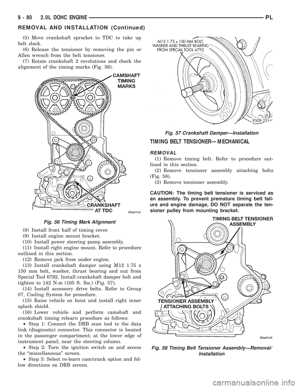
(5) Move crankshaft sprocket to TDC to take up
belt slack.
(6) Release the tensioner by removing the pin or
Allen wrench from the belt tensioner.
(7) Rotate crankshaft 2 revolutions and check the
alignment of the timing marks (Fig. 56).
(8) Install front half of timing cover.
(9) Install engine mount bracket.
(10) Install power steering pump assembly.
(11) Install right engine mount. Refer to procedure
outlined in this section.
(12) Remove jack from under engine.
(13) Install crankshaft damper using M12 1.75 x
150 mm bolt, washer, thrust bearing and nut from
Special Tool 6792. Install crankshaft damper bolt and
tighten to 142 N´m (105 ft. lbs.) (Fig. 57).
(14) Install accessory drive belts. Refer to Group
07, Cooling System for procedure.
(15) Raise vehicle on hoist and install right inner
splash shield.
(16) Lower vehicle and perform camshaft and
crankshaft timing relearn procedure as follows:
²Step 1: Connect the DRB scan tool to the data
link (diagnostic) connector. This connector is located
in the passenger compartment; at the lower edge of
instrument panel; near the steering column.
²Step 2: Turn the ignition switch on and access
the ªmiscellaneousº screen.
²Step 3: Select re-learn cam/crank option and fol-
low directions on DRB screen.
TIMING BELT TENSIONERÐMECHANICAL
REMOVAL
(1) Remove timing belt. Refer to procedure out-
lined in this section.
(2) Remove tensioner assembly attaching bolts
(Fig. 58).
(3) Remove tensioner assembly.
CAUTION: The timing belt tensioner is serviced as
an assembly. To prevent premature timing belt fail-
ure and engine damage, DO NOT separate the ten-
sioner pulley from mounting bracket.
Fig. 56 Timing Mark Alignment
Fig. 57 Crankshaft DamperÐInstallation
Fig. 58 Timing Belt Tensioner AssemblyÐRemoval/
Installation
9 - 80 2.0L DOHC ENGINEPL
REMOVAL AND INSTALLATION (Continued)
Page 862 of 1200

GENERAL INFORMATION
INTRODUCTION
All engines used in this section have a sequential
Multi-Port Electronic Fuel Injection system. The MPI
system is computer regulated and provides precise
air/fuel ratios for all driving conditions. The Power-
train Control Module (PCM) operates the fuel injec-
tion system.
The PCM regulates:
²Ignition timing
²Air/fuel ratio
²Emission control devices
²Cooling fan
²Charging system
²Idle speed
²Vehicle speed control
Various sensors provide the inputs necessary for
the PCM to correctly operate these systems. In addi-
tion to the sensors, various switches also provide
inputs to the PCM.
All inputs to the PCM are converted into signals.
The PCM can adapt its programming to meet chang-
ing operating conditions.
Fuel is injected into the intake port above the
intake valve in precise metered amounts through
electrically operated injectors. The PCM fires the
injectors in a specific sequence. Under most operat-
ing conditions, the PCM maintains an air fuel ratio
of 14.7 parts air to 1 part fuel by constantly adjust-
ing injector pulse width. Injector pulse width is the
length of time the injector is open.
The PCM adjusts injector pulse width by opening
and closing the ground path to the injector. Engine
RPM (speed) and manifold absolute pressure (air
density) are the primary inputs that determine injec-
tor pulse width.
MODES OF OPERATION
As input signals to the PCM change, the PCM
adjusts its response to output devices. For example,
the PCM must calculate a different injector pulse
width and ignition timing for idle than it does for
Wide Open Throttle (WOT). There are several differ-
ent modes of operation that determine how the PCM
responds to the various input signals.
There are two different areas of operation, OPEN
LOOP and CLOSED LOOP.
During OPEN LOOP modes the PCM receives
input signals and responds according to preset PCM
programming. Inputs from the upstream and down-
stream heated oxygen sensors are not monitored dur-
ing OPEN LOOP modes, except for heated oxygen
sensor diagnostics (they are checked for shorted con-
ditions at all times).During CLOSED LOOP modes the PCM monitors
the inputs from the upstream and downstream
heated oxygen sensors. The upstream heated oxygen
sensor input tells the PCM if the calculated injector
pulse width resulted in the ideal air-fuel ratio of 14.7
to one. By monitoring the exhaust oxygen content
through the upstream heated oxygen sensor, the
PCM can fine tune injector pulse width. Fine tuning
injector pulse width allows the PCM to achieve opti-
mum fuel economy combined with low emissions.
For the PCM to enter CLOSED LOOP operation,
the following must occur:
(1) Engine coolant temperature must be over 35ÉF.
²If the coolant is over 35É the PCM will wait 44
seconds.
²If the coolant is over 50ÉF the PCM will wait 38
seconds.
²If the coolant is over 167ÉF the PCM will wait
11 seconds.
(2) For other temperatures the PCM will interpo-
late the correct waiting time.
(3) O2 sensor must read either greater than .745
volts or less than .1 volt.
(4) The multi-port fuel injection systems has the
following modes of operation:
²Ignition switch ON (Zero RPM)
²Engine start-up
²Engine warm-up
²Cruise
²Idle
²Acceleration
²Deceleration
²Wide Open Throttle
²Ignition switch OFF
(5) The engine start-up (crank), engine warm-up,
deceleration with fuel shutoff and wide open throttle
modes are OPEN LOOP modes. Under most operat-
ing conditions, the acceleration, deceleration (with
A/C on), idle and cruise modes,with the engine at
operating temperatureare CLOSED LOOP modes.
IGNITION SWITCH ON (ZERO RPM) MODE
When the ignition switch activates the fuel injec-
tion system, the following actions occur:
²The PCM monitors the engine coolant tempera-
ture sensor and throttle position sensor input. The
PCM determines basic fuel injector pulse width from
this input.
²The PCM determines atmospheric air pressure
from the MAP sensor input to modify injector pulse
width.
When the key is in the ON position and the engine
is not running (zero rpm), the Auto Shutdown (ASD)
and fuel pump relays de-energize after approximately
1 second. Therefore, battery voltage is not supplied to
the fuel pump, ignition coil, fuel injectors and heated
oxygen sensors.
PLFUEL SYSTEM 14 - 21
Page 865 of 1200

POWERTRAIN CONTROL MODULE
The Powertrain Control Module (PCM) is a digital
computer containing a microprocessor (Fig. 2). The
PCM receives input signals from various switches
and sensors that are referred to as PCM Inputs.
Based on these inputs, the PCM adjusts various
engine and vehicle operations through devices that
are referred to as PCM Outputs.
PCM Inputs:
²Air Conditioning Controls
²Battery Voltage
²Battery Temperature Sensor
²Brake Switch
²Camshaft Position Sensor
²Crankshaft Position Sensor
²Engine Coolant Temperature Sensor
²Fuel Level Sensor
²Ignition Switch
²Intake Air Temperature Sensor
²Knock Sensor
²Manifold Absolute Pressure (MAP) Sensor
²Oxygen Sensors
²Power Steering Pressure Switch
²SCI Receive
²Speed Control Switches
²Throttle Position Sensor
²Transmission Park/Neutral Switch (automatic
transmission)
²Vehicle Speed Sensor
PCM Outputs:
²Air Conditioning WOT Relay
²Auto Shutdown (ASD) Relay
²Charging Indicator Lamp
²Data Link Connector
²Duty Cycle EVAP Canister Purge Solenoid
²EGR Solenoid
²Fuel Injectors
²Fuel Pump Relay²Generator Field
²Idle Air Control Motor
²Ignition Coils
²Malfunction Indicator (Check Engine) Lamp
²Radiator Fan Relay
²Speed Control Solenoids
²Tachometer
²Torque Convertor Clutch Solenoid
Based on inputs it receives, the PCM adjusts fuel
injector pulse width, idle speed, ignition spark
advance, ignition coil dwell and EVAP canister purge
operation. The PCM regulates the cooling fan, air
conditioning and speed control systems. The PCM
changes generator charge rate by adjusting the gen-
erator field. The PCM also performs diagnostics.
The PCM adjusts injector pulse width (air-fuel
ratio) based on the following inputs.
²Battery voltage
²Coolant temperature
²Intake air temperature
²Exhaust gas content (oxygen sensor)
²Engine speed (crankshaft position sensor)
²Manifold absolute pressure
²Throttle position
The PCM adjusts ignition timing based on the fol-
lowing inputs.
²Coolant temperature
²Intake air temperature
²Engine speed (crankshaft position sensor)
²Knock sensor
²Manifold absolute pressure
²Throttle position
²Transmission gear selection (park/neutral
switch)
The PCM also adjusts engine idle speed through
the idle air control motor based on the following
inputs.
²Air conditioning sense
²Battery voltage
²Battery temperature
²Brake switch
²Coolant temperature
²Engine speed (crankshaft position sensor)
²Engine run time
²Manifold absolute pressure
²Power steering pressure switch
²Throttle position
²Transmission gear selection (park/neutral
switch)
²Vehicle distance (speed)
The Auto Shutdown (ASD) and fuel pump relays
are mounted externally, but turned on and off by the
PCM.
The crankshaft position sensor signal is sent to the
PCM. If the PCM does not receive the signal within
approximately one second of engine cranking, it deac-
Fig. 2 Powertrain Control Module (PCM)
14 - 24 FUEL SYSTEMPL
DESCRIPTION AND OPERATION (Continued)
Page 876 of 1200

send incorrect signals. The PCM substitutes for the
incorrect signals with inputs from other sensors.
If the PCM detects active engine misfire severe
enough to cause catalyst damage, it flashes the MIL.
At the same time the PCM also sets a Diagnostic
Trouble Code (DTC).
For signals that can trigger the MIL (Check
Engine Lamp) refer to Group 25, On-Board
Dianostics.
SOLID STATE FAN RELAYÐPCM OUTPUT
The radiator fan runs when coolant temperature
and A/C system pressure demand cooling. The radia-
tor fan circuit contains a Solid State Fan Relay
(SSFR). Refer to the Group 8W for a circuit sche-
matic.
A 5 volt signal is supplied to the SSFR. The PCM
provides a pulsed ground for the SSFR. Depending
upon the amount of pulse on time, the SSFR puts out
a proportional voltage to the fan motor at the lower
speed. For instance, if the on time is 30 percent, then
the voltage to the fan motor will be 3.6 volts.
When engine coolant reaches approximately 99ÉC
(210ÉF) the PCM grounds the SSFR relay. When the
PCM grounds the relay it operates at a 30% duty
cycle and immediately ramps up to 100% duty cycle.
The PCM de-energizes the SSFR relay when coolant
temperature drops to approximately 93ÉC (199ÉF).
Also, when the air conditioning pressure switch
closes, the PCM grounds the SSFR. The air condi-
tioning switch closes at 285 psi610 psi. When air
conditioning pressure drops approximately 40 psi, the
pressure switch opens and the fan turns off.
The SSFR relay is located on the left front inner
frame just behind the radiator.
SPEED CONTROLÐPCM INPUT
The speed control system provides five separate
voltages (inputs) to the Powertrain Control Module
(PCM). The voltages correspond to the ON/OFF, SET,
RESUME and CANCEL.
The speed control ON voltage informs the PCM
that the speed control system has been activated.
The speed control SET voltage informs the PCM that
a fixed vehicle speed has been selected. The speed
control RESUME voltage indicates the previous fixed
speed is requested. The speed control CANCEL volt-
age tells the PCM to deactivate but retain set speed
in memory (same as depressing the brake pedal). The
speed control OFF voltage tells the PCM that the
speed control system has deactivated. Refer to Group
8H for more speed control information.
SCI RECEIVEÐPCM OUTPUT
SCI Receive is the serial data communication
receive circuit for the DRB scan tool. The Powertrain
Control Module (PCM) receives data from the DRB
through the SCI Receive circuit.
TACHOMETERÐPCM OUTPUT
The PCM operates the tachometer on the instru-
ment panel. The PCM calculates engine RPM from
the crankshaft position sensor input.
TORQUE CONVERTOR CLUTCH SOLENOIDÐPCM
OUTPUT
Three-speed automatic transaxles use a torque con-
verter clutch solenoid. The PCM controls the engage-
ment of the torque converter clutch through the
solenoid (Fig. 29). The torque converter clutch is
engaged up only in direct drive mode. Refer to Group
21 for transmission information.
DIAGNOSIS AND TESTING
VISUAL INSPECTIONÐSOHC
Before diagnosing or servicing the fuel injection
system, perform a visual inspection for loose, discon-
nected, or misrouted wires and hoses (Fig. 30). A
thorough visual inspection that includes the following
checks saves unnecessary test and diagnostic time.
(1) Inspect the battery connections. Clean corroded
terminals (Fig. 31).
(2) Check the 2 PCM 40-way connector for
stretched wires on pushed out terminals (Fig. 31).
Fig. 29 Torque Convertor Clutch Solenoid
PLFUEL SYSTEM 14 - 35
DESCRIPTION AND OPERATION (Continued)