1999 DODGE NEON cooling
[x] Cancel search: coolingPage 746 of 1200
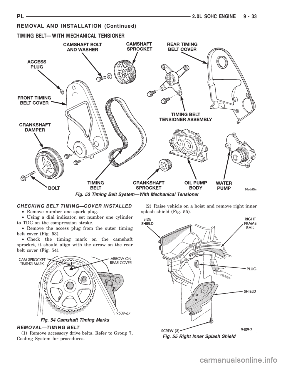
TIMING BELTÐWITH MECHANICAL TENSIONER
CHECKING BELT TIMINGÐCOVER INSTALLED
²Remove number one spark plug.
²Using a dial indicator, set number one cylinder
to TDC on the compression stroke.
²Remove the access plug from the outer timing
belt cover (Fig. 53).
²Check the timing mark on the camshaft
sprocket, it should align with the arrow on the rear
belt cover (Fig. 54).
REMOVALÐTIMING BELT
(1) Remove accessory drive belts. Refer to Group 7,
Cooling System for procedures.(2) Raise vehicle on a hoist and remove right inner
splash shield (Fig. 55).
Fig. 53 Timing Belt SystemÐWith Mechanical Tensioner
Fig. 54 Camshaft Timing Marks
Fig. 55 Right Inner Splash Shield
PL2.0L SOHC ENGINE 9 - 33
REMOVAL AND INSTALLATION (Continued)
Page 748 of 1200
CAMSHAFT AND CRANKSHAFT TIMING
PROCEDURE AND BELT INSTALLATIONÐ
SOHC ENGINE
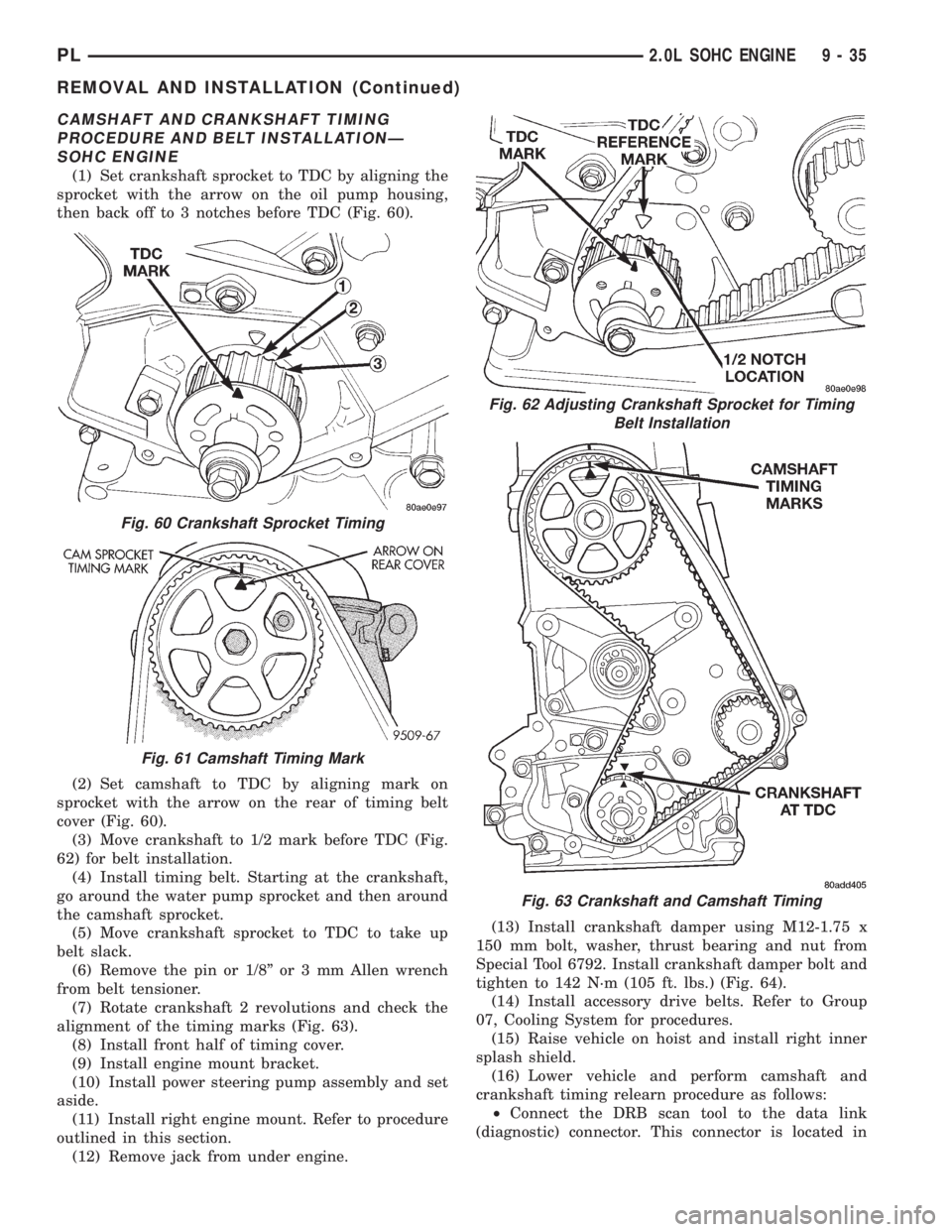
(1) Set crankshaft sprocket to TDC by aligning the
sprocket with the arrow on the oil pump housing,
then back off to 3 notches before TDC (Fig. 60).
(2) Set camshaft to TDC by aligning mark on
sprocket with the arrow on the rear of timing belt
cover (Fig. 60).
(3) Move crankshaft to 1/2 mark before TDC (Fig.
62) for belt installation.
(4) Install timing belt. Starting at the crankshaft,
go around the water pump sprocket and then around
the camshaft sprocket.
(5) Move crankshaft sprocket to TDC to take up
belt slack.
(6) Remove the pin or 1/8º or 3 mm Allen wrench
from belt tensioner.
(7) Rotate crankshaft 2 revolutions and check the
alignment of the timing marks (Fig. 63).
(8) Install front half of timing cover.
(9) Install engine mount bracket.
(10) Install power steering pump assembly and set
aside.
(11) Install right engine mount. Refer to procedure
outlined in this section.
(12) Remove jack from under engine.(13) Install crankshaft damper using M12-1.75 x
150 mm bolt, washer, thrust bearing and nut from
Special Tool 6792. Install crankshaft damper bolt and
tighten to 142 N´m (105 ft. lbs.) (Fig. 64).
(14) Install accessory drive belts. Refer to Group
07, Cooling System for procedures.
(15) Raise vehicle on hoist and install right inner
splash shield.
(16) Lower vehicle and perform camshaft and
crankshaft timing relearn procedure as follows:
²Connect the DRB scan tool to the data link
(diagnostic) connector. This connector is located in
Fig. 60 Crankshaft Sprocket Timing
Fig. 61 Camshaft Timing Mark
Fig. 62 Adjusting Crankshaft Sprocket for Timing
Belt Installation
Fig. 63 Crankshaft and Camshaft Timing
PL2.0L SOHC ENGINE 9 - 35
REMOVAL AND INSTALLATION (Continued)
Page 759 of 1200
(6) Tap the piston down in cylinder bore, using a
hammer handle. At the same time, guide connecting
rod into position on connecting rod journal.
(7) Install rod caps. InstallNewbolts and tighten
to 27 N´m (20 ft.lb.) Plus 1/4 turn.
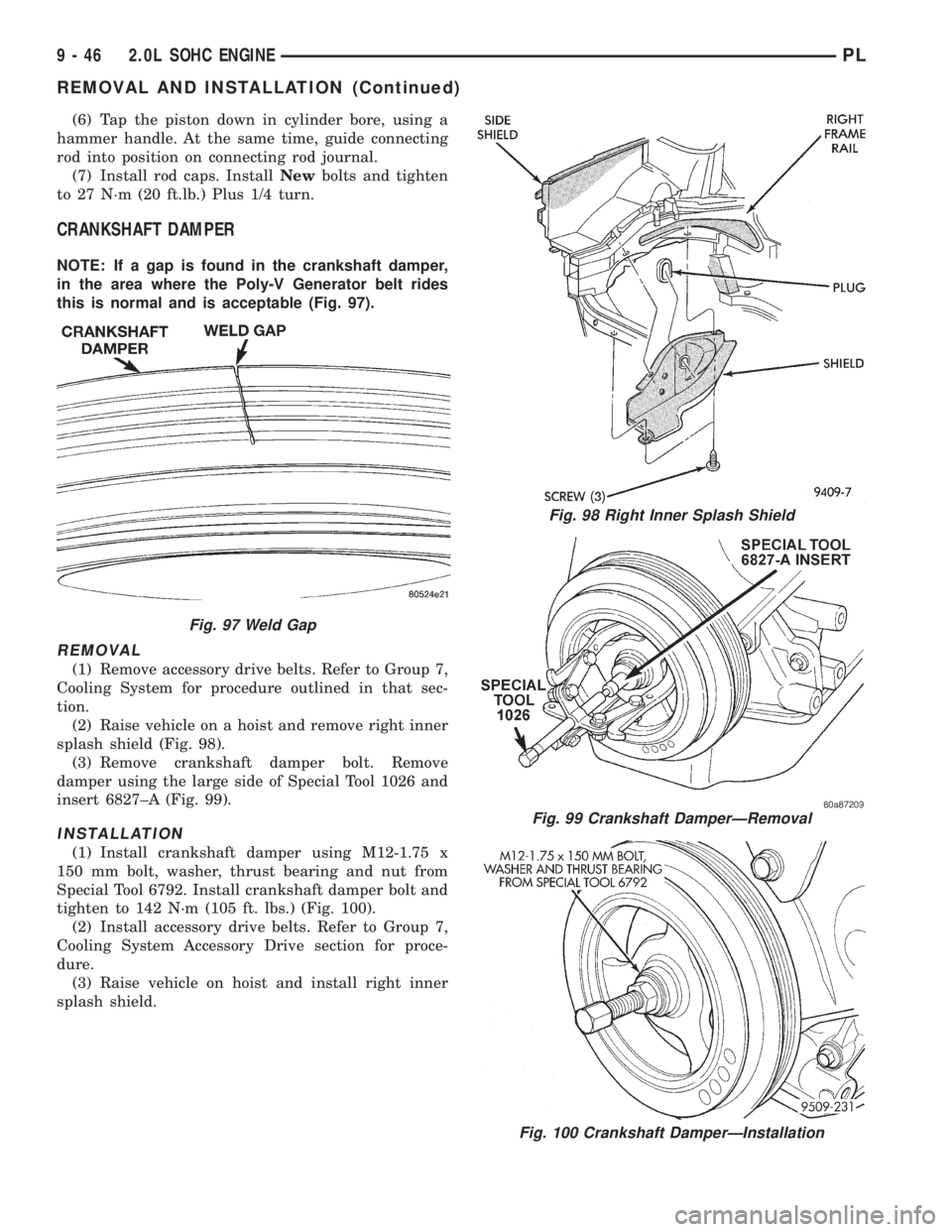
CRANKSHAFT DAMPER
NOTE: If a gap is found in the crankshaft damper,
in the area where the Poly-V Generator belt rides
this is normal and is acceptable (Fig. 97).
REMOVAL
(1) Remove accessory drive belts. Refer to Group 7,
Cooling System for procedure outlined in that sec-
tion.
(2) Raise vehicle on a hoist and remove right inner
splash shield (Fig. 98).
(3) Remove crankshaft damper bolt. Remove
damper using the large side of Special Tool 1026 and
insert 6827±A (Fig. 99).
INSTALLATION
(1) Install crankshaft damper using M12-1.75 x
150 mm bolt, washer, thrust bearing and nut from
Special Tool 6792. Install crankshaft damper bolt and
tighten to 142 N´m (105 ft. lbs.) (Fig. 100).
(2) Install accessory drive belts. Refer to Group 7,
Cooling System Accessory Drive section for proce-
dure.
(3) Raise vehicle on hoist and install right inner
splash shield.
Fig. 97 Weld Gap
Fig. 98 Right Inner Splash Shield
Fig. 99 Crankshaft DamperÐRemoval
Fig. 100 Crankshaft DamperÐInstallation
9 - 46 2.0L SOHC ENGINEPL
REMOVAL AND INSTALLATION (Continued)
Page 772 of 1200
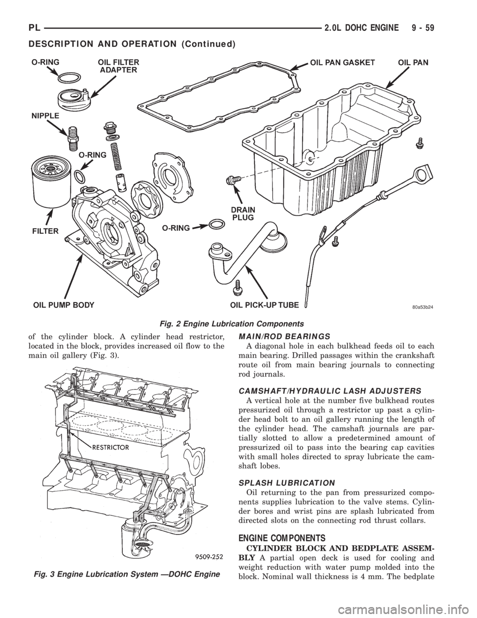
of the cylinder block. A cylinder head restrictor,
located in the block, provides increased oil flow to the
main oil gallery (Fig. 3).MAIN/ROD BEARINGS
A diagonal hole in each bulkhead feeds oil to each
main bearing. Drilled passages within the crankshaft
route oil from main bearing journals to connecting
rod journals.
CAMSHAFT/HYDRAULIC LASH ADJUSTERS
A vertical hole at the number five bulkhead routes
pressurized oil through a restrictor up past a cylin-
der head bolt to an oil gallery running the length of
the cylinder head. The camshaft journals are par-
tially slotted to allow a predetermined amount of
pressurized oil to pass into the bearing cap cavities
with small holes directed to spray lubricate the cam-
shaft lobes.
SPLASH LUBRICATION
Oil returning to the pan from pressurized compo-
nents supplies lubrication to the valve stems. Cylin-
der bores and wrist pins are splash lubricated from
directed slots on the connecting rod thrust collars.
ENGINE COMPONENTS
CYLINDER BLOCK AND BEDPLATE ASSEM-
BLYA partial open deck is used for cooling and
weight reduction with water pump molded into the
block. Nominal wall thickness is 4 mm. The bedplate
Fig. 2 Engine Lubrication Components
Fig. 3 Engine Lubrication System ÐDOHC Engine
PL2.0L DOHC ENGINE 9 - 59
DESCRIPTION AND OPERATION (Continued)
Page 778 of 1200
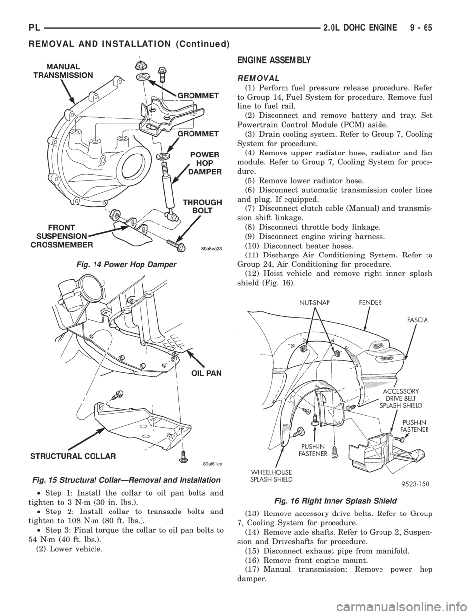
²Step 1: Install the collar to oil pan bolts and
tighten to 3 N´m (30 in. lbs.).
²Step 2: Install collar to transaxle bolts and
tighten to 108 N´m (80 ft. lbs.).
²Step 3: Final torque the collar to oil pan bolts to
54 N´m (40 ft. lbs.).
(2) Lower vehicle.
ENGINE ASSEMBLY
REMOVAL
(1) Perform fuel pressure release procedure. Refer
to Group 14, Fuel System for procedure. Remove fuel
line to fuel rail.
(2) Disconnect and remove battery and tray. Set
Powertrain Control Module (PCM) aside.
(3) Drain cooling system. Refer to Group 7, Cooling
System for procedure.
(4) Remove upper radiator hose, radiator and fan
module. Refer to Group 7, Cooling System for proce-
dure.
(5) Remove lower radiator hose.
(6) Disconnect automatic transmission cooler lines
and plug. If equipped.
(7) Disconnect clutch cable (Manual) and transmis-
sion shift linkage.
(8) Disconnect throttle body linkage.
(9) Disconnect engine wiring harness.
(10) Disconnect heater hoses.
(11) Discharge Air Conditioning System. Refer to
Group 24, Air Conditioning for procedure.
(12) Hoist vehicle and remove right inner splash
shield (Fig. 16).
(13) Remove accessory drive belts. Refer to Group
7, Cooling System for procedure.
(14) Remove axle shafts. Refer to Group 2, Suspen-
sion and Driveshafts for procedure.
(15) Disconnect exhaust pipe from manifold.
(16) Remove front engine mount.
(17) Manual transmission: Remove power hop
damper.
Fig. 14 Power Hop Damper
Fig. 15 Structural CollarÐRemoval and Installation
Fig. 16 Right Inner Splash Shield
PL2.0L DOHC ENGINE 9 - 65
REMOVAL AND INSTALLATION (Continued)
Page 779 of 1200
(18) Lower vehicle. Remove air cleaner assembly.
(19) Remove power steering pump and reservoir,
Set them aside.
(20) Remove A/C compressor.
(21) Remove ground straps to body.
(22) Raise vehicle enough to allow engine dolly
and cradle Special Tools 6135 and 6710 to be
installed under vehicle.
(23) Loosen engine support posts to allow move-
ment for positioning onto engine locating holes and
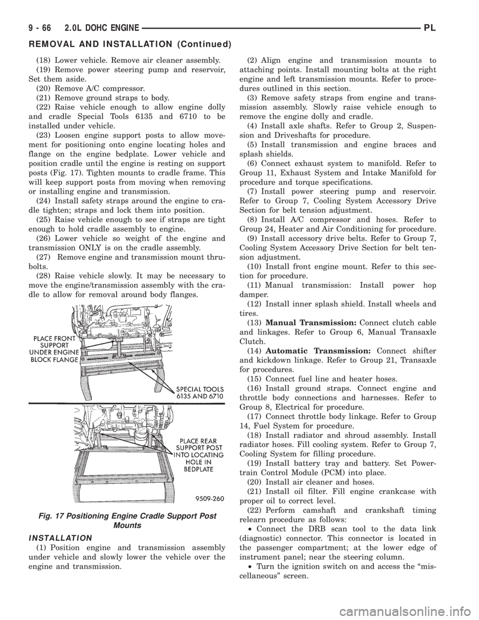
flange on the engine bedplate. Lower vehicle and
position cradle until the engine is resting on support
posts (Fig. 17). Tighten mounts to cradle frame. This
will keep support posts from moving when removing
or installing engine and transmission.
(24) Install safety straps around the engine to cra-
dle tighten; straps and lock them into position.
(25) Raise vehicle enough to see if straps are tight
enough to hold cradle assembly to engine.
(26) Lower vehicle so weight of the engine and
transmission ONLY is on the cradle assembly.
(27) Remove engine and transmission mount thru-
bolts.
(28) Raise vehicle slowly. It may be necessary to
move the engine/transmission assembly with the cra-
dle to allow for removal around body flanges.
INSTALLATION
(1) Position engine and transmission assembly
under vehicle and slowly lower the vehicle over the
engine and transmission.(2) Align engine and transmission mounts to
attaching points. Install mounting bolts at the right
engine and left transmission mounts. Refer to proce-
dures outlined in this section.
(3) Remove safety straps from engine and trans-
mission assembly. Slowly raise vehicle enough to
remove the engine dolly and cradle.
(4) Install axle shafts. Refer to Group 2, Suspen-
sion and Driveshafts for procedure.
(5) Install transmission and engine braces and
splash shields.
(6) Connect exhaust system to manifold. Refer to
Group 11, Exhaust System and Intake Manifold for
procedure and torque specifications.
(7) Install power steering pump and reservoir.
Refer to Group 7, Cooling System Accessory Drive
Section for belt tension adjustment.
(8) Install A/C compressor and hoses. Refer to
Group 24, Heater and Air Conditioning for procedure.
(9) Install accessory drive belts. Refer to Group 7,
Cooling System Accessory Drive Section for belt ten-
sion adjustment.
(10) Install front engine mount. Refer to this sec-
tion for procedure.
(11) Manual transmission: Install power hop
damper.
(12) Install inner splash shield. Install wheels and
tires.
(13)Manual Transmission:Connect clutch cable
and linkages. Refer to Group 6, Manual Transaxle
Clutch.
(14)Automatic Transmission:Connect shifter
and kickdown linkage. Refer to Group 21, Transaxle
for procedures.
(15) Connect fuel line and heater hoses.
(16) Install ground straps. Connect engine and
throttle body connections and harnesses. Refer to
Group 8, Electrical for procedure.
(17) Connect throttle body linkage. Refer to Group
14, Fuel System for procedure.
(18) Install radiator and shroud assembly. Install
radiator hoses. Fill cooling system. Refer to Group 7,
Cooling System for filling procedure.
(19) Install battery tray and battery. Set Power-
train Control Module (PCM) into place.
(20) Install air cleaner and hoses.
(21) Install oil filter. Fill engine crankcase with
proper oil to correct level.
(22) Perform camshaft and crankshaft timing
relearn procedure as follows:
²Connect the DRB scan tool to the data link
(diagnostic) connector. This connector is located in
the passenger compartment; at the lower edge of
instrument panel; near the steering column.
²Turn the ignition switch on and access the ªmis-
cellaneousº screen.
Fig. 17 Positioning Engine Cradle Support Post
Mounts
9 - 66 2.0L DOHC ENGINEPL
REMOVAL AND INSTALLATION (Continued)
Page 785 of 1200
REMOVAL
(1) Perform fuel system pressure release procedure
before attempting any repairs.Refer to Group 14,
Fuel System.
(2) Disconnect negative battery cable. Drain cool-
ing system. Refer to Group 7, Cooling System.
(3) Remove air cleaner duct and air cleaner, dis-
connect all vacuum lines, electrical wiring and fuel
line from fuel rail and throttle body.
(4) Remove throttle linkage.
(5) Remove accessory drive belts. Refer to Group 7,
Cooling System for procedure.
(6) Remove power brake vacuum hose from intake
manifold.
(7) Raise vehicle and remove exhaust pipe from
manifold.
(8) Remove power steering pump assembly and set
aside.
(9) Disconnect coil pack wiring connector and
remove coil pack from engine.
(10) Remove cam sensor and fuel injectors wiring
connectors.
(11) Remove timing belt, timing belt tensioner, and
camshaft sprocket. Refer to procedure outlined in
this section.
(12) Remove inner timing belt cover.
(13) Remove cylinder head cover.
(14) Remove camshaft and cam follower assem-
blies. Refer to Camshaft Service for removal proce-
dure outlined in this section.
(15) Remove cylinder head bolts.
CAUTION: Use only a plastic scraper to remove
gasket material on the aluminum head sealing sur-
faces to prevent damage to cylinder head.
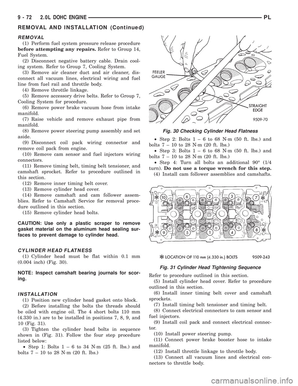
CYLINDER HEAD FLATNESS
(1) Cylinder head must be flat within 0.1 mm
(0.004 inch) (Fig. 30).
NOTE: Inspect camshaft bearing journals for scor-
ing.
INSTALLATION
(1) Position new cylinder head gasket onto block.
(2) Before installing the bolts the threads should
be oiled with engine oil. The 4 short bolts 110 mm
(4.330 in.) are to be installed in positions 7, 8, 9, and
10 (Fig. 31).
(3) Tighten the cylinder head bolts in sequence
shown in (Fig. 31). Follow the four step procedure
listed below:
²Step 1: Bolts1±6to34N´m(25ft.lbs.) and
bolts7±10to28N´m(20ft.lbs.)²Step 2: Bolts1±6to68N´m(50ft.lbs.) and
bolts7±10to28N´m(20ft.lbs.)
²Step 3: Bolts1±6to68N´m(50ft.lbs.) and
bolts7±10to28N´m(20ft.lbs.)
²Step 4: Turn all bolts an additional 90É (1/4
turn).Do not use a torque wrench for this step.
(4) Install cam follower assemblies and camshafts.
Refer to procedure outlined in this section.
(5) Install cylinder head cover. Refer to procedure
outlined in this section.
(6) Install inner timing belt cover and camshaft
sprockets.
(7) Install timing belt tensioner and timing belt.
(8) Connect electrical connectors to cam sensor and
fuel injectors.
(9) Install coil pack and connect electrical connec-
tor.
(10) Install power steering pump.
(11) Connect power brake booster hose to intake
manifold.
(12) Install throttle linkage to throttle body.
(13) Connect all vacuum lines and electrical con-
nectors to throttle body.
Fig. 30 Checking Cylinder Head Flatness
Fig. 31 Cylinder Head Tightening Sequence
9 - 72 2.0L DOHC ENGINEPL
REMOVAL AND INSTALLATION (Continued)
Page 786 of 1200
(14) Connect fuel supply hose to fuel rail.
(15) Install air cleaner duct and air cleaner.
(16) Install accessory drive belts. Refer to Group
07, Cooling System for procedures.
(17) Raise vehicle and connect exhaust system to
exhaust manifold.
(18) Lower vehicle and connect negative cable to
battery.
(19) With DRB scan tool use ASD Fuel System
Test to pressurize fuel system. Check for fuel leaks.
CAUTION: When using the ASD Fuel System Test,
the Auto Shutdown (ASD) relay will remain ener-
gized for 7 minutes, or until the ignition switch is
turned to the OFF position, or Stop All Test is
selected.
(20) Perform camshaft and crankshaft timing
relearn procedure as follows:
²Step 1: Connect the DRB scan tool to the data
link (diagnostic) connector. This connector is located
in the passenger compartment; at the lower edge of
instrument panel; near the steering column.
²Step 2: Turn the ignition switch on and access
the ªmiscellaneousº screen.
²Step 3: Select re-learn cam/crank option and fol-
low directions on DRB screen.
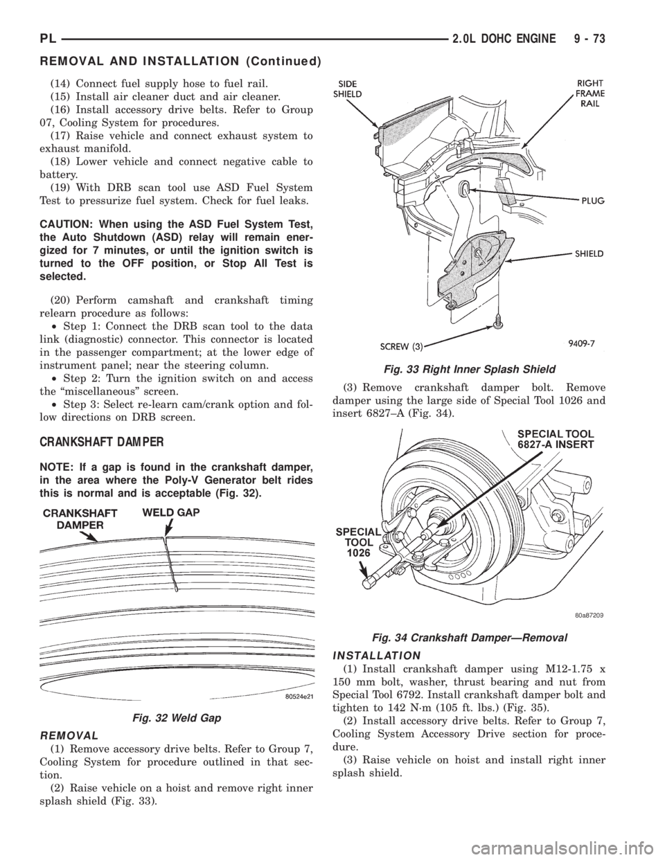
CRANKSHAFT DAMPER
NOTE: If a gap is found in the crankshaft damper,
in the area where the Poly-V Generator belt rides
this is normal and is acceptable (Fig. 32).
REMOVAL
(1) Remove accessory drive belts. Refer to Group 7,
Cooling System for procedure outlined in that sec-
tion.
(2) Raise vehicle on a hoist and remove right inner
splash shield (Fig. 33).(3) Remove crankshaft damper bolt. Remove
damper using the large side of Special Tool 1026 and
insert 6827±A (Fig. 34).
INSTALLATION
(1) Install crankshaft damper using M12-1.75 x
150 mm bolt, washer, thrust bearing and nut from
Special Tool 6792. Install crankshaft damper bolt and
tighten to 142 N´m (105 ft. lbs.) (Fig. 35).
(2) Install accessory drive belts. Refer to Group 7,
Cooling System Accessory Drive section for proce-
dure.
(3) Raise vehicle on hoist and install right inner
splash shield.
Fig. 32 Weld Gap
Fig. 33 Right Inner Splash Shield
Fig. 34 Crankshaft DamperÐRemoval
PL2.0L DOHC ENGINE 9 - 73
REMOVAL AND INSTALLATION (Continued)