1999 DODGE NEON cooling
[x] Cancel search: coolingPage 890 of 1200
(6) Connect the DRB scan tool to the data link
connector inside the passenger compartment.
(7) Run engine in Park or Neutral until the cooling
fan has cycled on and off at least once (180ÉF).
(8) Using the DRB scan tool, access Minimum Air-
flow Idle Speed.
(9) The following will then occur:
²Idle air control motor will fully close
²Idle spark advance will become fixed
²PCM will go open loop enriched
²DRB scan tool displays engine RPM
(10) If idle RPM is within the range shown in the
Idle Specification chart, throttle body minimum air-
flow is set correctly.
IDLE SPECIFICATION Ð2.0L ENGINEOdometer Reading Idle RPM
Below 1000 Miles.................550±1300 RPM
Above 1000 Miles.................600±1300 Miles
(11) If idle RPM is above specifications, use the
DRB scan tool to check idle air control motor opera-
tion. If idle air control motor is OK, replace throttle
body. If idle air flow is below specification, shut off
the engine and clean the throttle body as follows:
WARNING: CLEAN THROTTLE BODY IN A WELL
VENTILATED AREA. WEAR RUBBER OR BUTYL
GLOVES, DO NOT LET MOPAR PARTS CLEANER
COME IN CONTACT WITH EYES OR SKIN. AVOID
INGESTING THE CLEANER. WASH THOROUGHLY
AFTER USING CLEANER.
(a) Remove the throttle body from engine.
(b) While holding the throttle open, spray the
entire throttle body bore and the manifold side of
the throttle plate with Mopar Parts Cleaner.Only
use Mopar Parts Cleaner to clean the throttle
body.
(c) Using a soft scuff pad, clean the top and bot-
tom of throttle body bore and the edges and mani-
fold side of the throttle blade.The edges of the
throttle blade and portions of the throttle
bore that are closest to the throttle blade
when closed, must be free of deposits.
(d) Use compressed air to dry the throttle body.
(e) Inspect throttle body for foreign material.
(f) Install throttle body on manifold.
(g) Repeat steps 1 through 14. If the minimum
air flow is still not within specifications, the prob-
lem is not caused by the throttle body.
(12) Shut off engine.
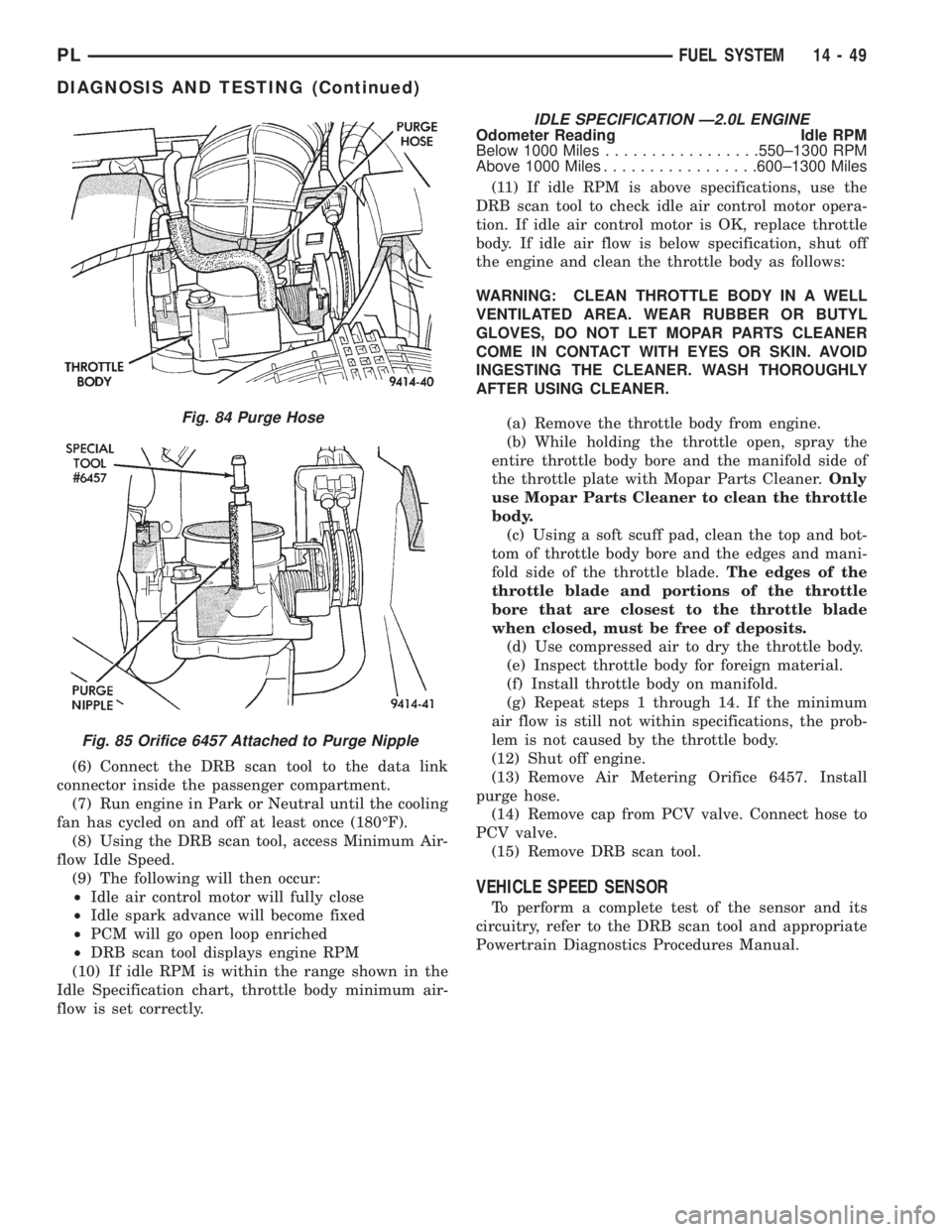
(13) Remove Air Metering Orifice 6457. Install
purge hose.
(14) Remove cap from PCV valve. Connect hose to
PCV valve.
(15) Remove DRB scan tool.
VEHICLE SPEED SENSOR
To perform a complete test of the sensor and its
circuitry, refer to the DRB scan tool and appropriate
Powertrain Diagnostics Procedures Manual.
Fig. 84 Purge Hose
Fig. 85 Orifice 6457 Attached to Purge Nipple
PLFUEL SYSTEM 14 - 49
DIAGNOSIS AND TESTING (Continued)
Page 897 of 1200

(3) Remove air cleaner element from front housing
(Fig. 106).
INSTALLATION
(1) Install air cleaner element into front housing.
(2) Rotate front of housing forward then lower into
place and locate tabs in slots. Fasten clasps on top of
air cleaner housing.
(3) Install air intake duct at air cleaner and intake
manifold.
ENGINE COOLANT TEMPERATURE SENSOR
The engine coolant temperature sensor threads
into the rear of the cylinder head (Fig. 107) or (Fig.
108).
REMOVAL
(1) With the engine cold, drain coolant until level
drops below cylinder head. Refer to Group 7, Cooling
System.
(2) Disconnect coolant sensor electrical connector.
(3) Remove coolant sensor.
INSTALLATION
(1) Install coolant sensor. Tighten sensor to 18
N´m (165 in. lbs.) torque.
(2) Attach electrical connector to sensor.
(3) Fill cooling system. Refer to Group 7, Cooling
System.
VEHICLE SPEED SENSOR
The vehicle speed sensor is located in the transmis-
sion extension housing (Fig. 109).
REMOVAL
(1) Disconnect electrical connector from sensor.
(2) Remove the sensor mounting bolt.
(3) Lift the sensor out of the transaxle extension
housing. Ensure the O-ring was removed with the
sensor.
Fig. 104 Air Intake Duct
Fig. 105 Removal/Installation of Air Inlet Duct
Fig. 106 Removal/Installation Air Cleaner Front
Housing and Element
Fig. 107 Engine Coolant Temperature SensorÐ
SOHC
14 - 56 FUEL SYSTEMPL
REMOVAL AND INSTALLATION (Continued)
Page 920 of 1200
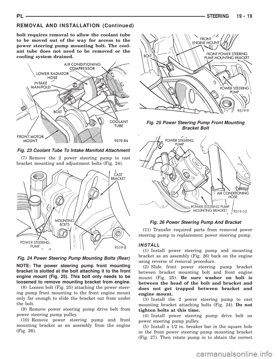
bolt requires removal to allow the coolant tube
to be moved out of the way for access to the
power steering pump mounting bolt. The cool-
ant tube does not need to be removed or the
cooling system drained.
(7) Remove the 2 power steering pump to cast
bracket mounting and adjustment bolts (Fig. 24).
NOTE: The power steering pump front mounting
bracket is slotted at the bolt attaching it to the front
engine mount (Fig. 25). This bolt only needs to be
loosened to remove mounting bracket from engine.
(8) Loosen bolt (Fig. 25) attaching the power steer-
ing pump front mounting to the front engine mount
only far enough to slide the bracket out from under
the bolt.
(9) Remove power steering pump drive belt from
power steering pump pulley.
(10) Remove power steering pump and front
mounting bracket as an assembly from the engine
(Fig. 26).(11) Transfer required parts from removed power
steering pump to replacement power steering pump.
INSTALL
(1) Install power steering pump and mounting
bracket as an assembly (Fig. 26) back on the engine
using reverse of removal procedure.
(2) Slide front power steering pump bracket
between bracket mounting bolt and front engine
mount (Fig. 25).Be sure washer on bolt is
between the head of the bolt and bracket and
does not get trapped between bracket and
engine mount.
(3) Install the 2 power steering pump to cast
mounting bracket attaching bolts (Fig. 24).Do not
tighten bolts at this time.
(4) Install power steering pump drive belt on
power steering pump pulley.
(5) Install a 1/2 in. breaker bar in the square hole
in the front power steering pump mounting bracket
(Fig. 27). Then rotate pump in to obtain the correct
Fig. 23 Coolant Tube To Intake Manifold Attachment
Fig. 24 Power Steering Pump Mounting Bolts (Rear)
Fig. 25 Power Steering Pump Front Mounting
Bracket Bolt
Fig. 26 Power Steering Pump And Bracket
PLSTEERING 19 - 19
REMOVAL AND INSTALLATION (Continued)
Page 921 of 1200
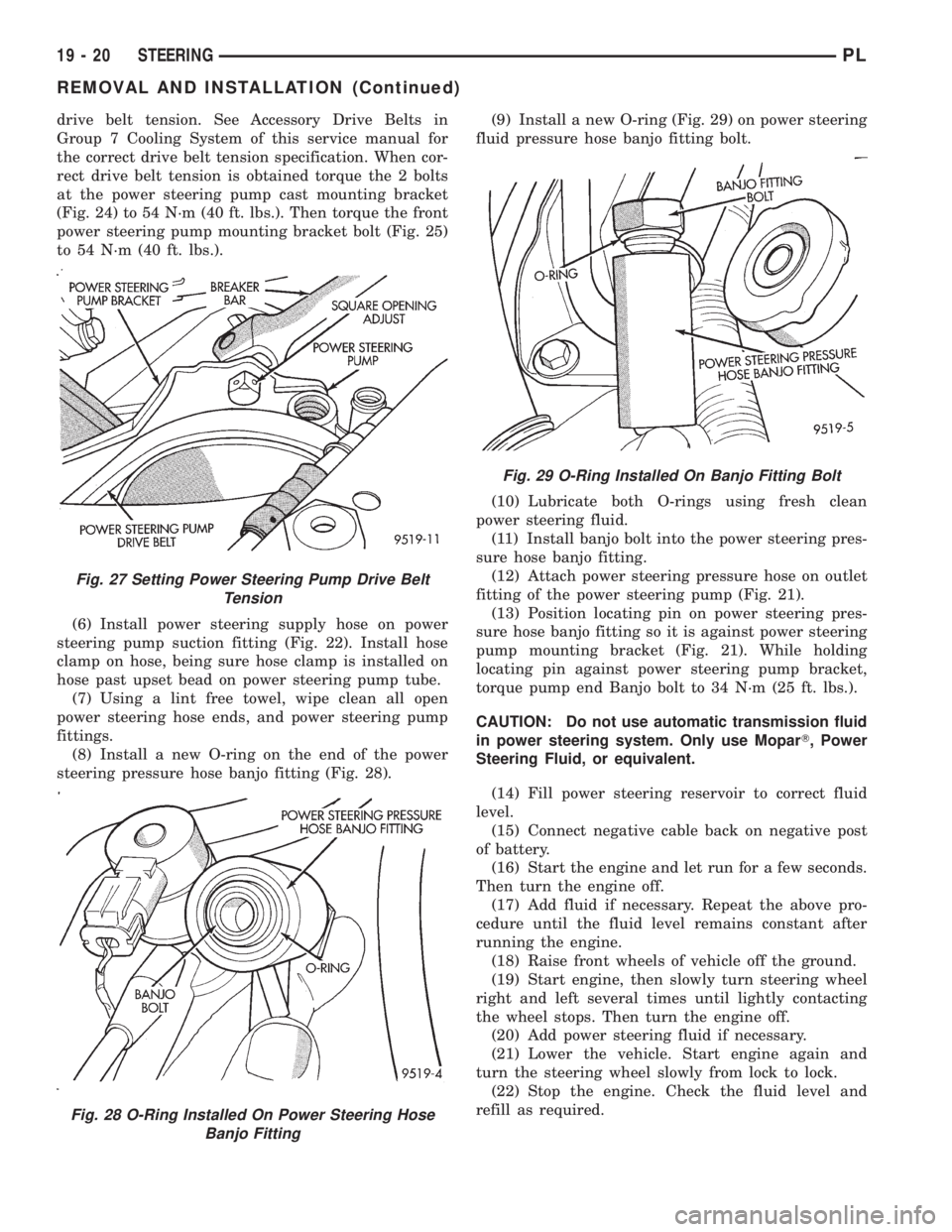
drive belt tension. See Accessory Drive Belts in
Group 7 Cooling System of this service manual for
the correct drive belt tension specification. When cor-
rect drive belt tension is obtained torque the 2 bolts
at the power steering pump cast mounting bracket
(Fig. 24) to 54 N´m (40 ft. lbs.). Then torque the front
power steering pump mounting bracket bolt (Fig. 25)
to 54 N´m (40 ft. lbs.).
(6) Install power steering supply hose on power
steering pump suction fitting (Fig. 22). Install hose
clamp on hose, being sure hose clamp is installed on
hose past upset bead on power steering pump tube.
(7) Using a lint free towel, wipe clean all open
power steering hose ends, and power steering pump
fittings.
(8) Install a new O-ring on the end of the power
steering pressure hose banjo fitting (Fig. 28).(9) Install a new O-ring (Fig. 29) on power steering
fluid pressure hose banjo fitting bolt.
(10) Lubricate both O-rings using fresh clean
power steering fluid.
(11) Install banjo bolt into the power steering pres-
sure hose banjo fitting.
(12) Attach power steering pressure hose on outlet
fitting of the power steering pump (Fig. 21).
(13) Position locating pin on power steering pres-
sure hose banjo fitting so it is against power steering
pump mounting bracket (Fig. 21). While holding
locating pin against power steering pump bracket,
torque pump end Banjo bolt to 34 N´m (25 ft. lbs.).
CAUTION: Do not use automatic transmission fluid
in power steering system. Only use MoparT, Power
Steering Fluid, or equivalent.
(14) Fill power steering reservoir to correct fluid
level.
(15) Connect negative cable back on negative post
of battery.
(16) Start the engine and let run for a few seconds.
Then turn the engine off.
(17) Add fluid if necessary. Repeat the above pro-
cedure until the fluid level remains constant after
running the engine.
(18) Raise front wheels of vehicle off the ground.
(19) Start engine, then slowly turn steering wheel
right and left several times until lightly contacting
the wheel stops. Then turn the engine off.
(20) Add power steering fluid if necessary.
(21) Lower the vehicle. Start engine again and
turn the steering wheel slowly from lock to lock.
(22) Stop the engine. Check the fluid level and
refill as required.
Fig. 27 Setting Power Steering Pump Drive Belt
Tension
Fig. 28 O-Ring Installed On Power Steering Hose
Banjo Fitting
Fig. 29 O-Ring Installed On Banjo Fitting Bolt
19 - 20 STEERINGPL
REMOVAL AND INSTALLATION (Continued)
Page 984 of 1200
NOTE: Transaxle operation requirements are differ-
ent for each vehicle and engine combination. Some
internal parts will be different to provide for this.
Therefore, when replacing parts, refer to the seven
digit part number stamped on rear of the transaxle
oil pan flange.
Within this transaxle, there are three primary
areas:
(1) Main center line plus valve body.
(2) Transfer shaft center line (includes governor
and parking sprag).
(3) Differential center line.
Center distances between the main rotating parts
in these three areas are held precise to maintain a
low noise level.
The torque converter, transaxle area, and differen-
tial are housed in an integral aluminum die casting.
The differential oil sump is common with the
transaxle sump. Separate filling of the differen-
tial is NOT necessary.
The torque converter is attached to the crankshaft
through a flexible driving plate. Cooling of the con-
verter is accomplished by circulating the transaxle
fluid through a remote cooler. There are two types of
coolers used. An oil-to-water type cooler located in
the radiator side tank and/or an oil-to-air heat
exchanger. The torque converter assembly is a sealed
unit that cannot be disassembled.
The transaxle fluid is filtered by an internal filter
attached to the lower side of the valve body assembly.
Engine torque is transmitted to the torque con-
verter and then through the input shaft to multiple-
disc clutches in the transaxle. The power flow
depends on the application of the clutches and bands.
Refer to Elements in Use Chart in Diagnosis and
Tests section.
The transaxle consists of:
²Two multiple-disc clutches
²An overrunning clutch
²Two servos
²A hydraulic accumulator
²Two bands
²Two planetary gear sets
This provides three forward ratios and a reverse
ratio. The common sun gear of the planetary gear
sets is connected to the front clutch by a driving
shell. The driving shell is splined to the sun gear and
front clutch retainer. The hydraulic system consists
of an oil pump and a single valve body which con-
tains all of the valves except the governor valves.
The transaxle sump and differential sump are both
vented through the dipstick. Output torque from the
main center line is delivered through helical gears to
the transfer shaft. This gear set is a factor in the
transaxle final drive (axle) ratio. The shaft also car-
ries the governor and parking sprag. An integral heli-cal gear on the transfer shaft drives the differential
ring gear. The final drive gearing is completed with
one of two gear ratios; 2.98 or 3.19 depending on
model and application.
FLUID LEVEL AND CONDITION
NOTE: The transmission and differential sump have
a common oil sump with a communicating opening
between the two.
The torque converter fills in both the P (Park) and
N (Neutral) positions. Place the selector lever in P
(Park) to be sure that the fluid level check is accu-
rate.The engine should be running at idle
speed for at least one minute, with the vehicle
on level ground. This will ensure complete oil
level stabilization between differential and
transmission.The fluid should be at normal operat-
ing temperature (approximately 82É C. or 180É F.).
The fluid level is correct if it is in the HOT region
(cross-hatched area) on the dipstick.
Low fluid level can cause a variety of conditions,
because it allows the pump to take in air along with
the fluid. As in any hydraulic system, air bubbles
make the fluid spongy therefore, pressures will be
low and will build up slowly.
Improper filling also can raise the fluid level too
high. When the transaxle has too much fluid, the
gears churn up foam and cause the same conditions
that occur with a low fluid level.
In either case, the air bubbles can cause overheat-
ing, fluid oxidation, and varnishing. This can inter-
fere with normal valve, clutch, and servo operation.
Foaming also can result in fluid escaping from the
transaxle dipstick, where it may be mistaken for a
leak.
Along with fluid level, it is important to check the
condition of the fluid. When the fluid smells burned,
or is contaminated with metal or friction material
particles, a complete transaxle overhaul is needed.
Be sure to examine the fluid on the dipstick closely.
If there is any doubt about its condition, drain out a
sample for a double check.
SELECTION OF LUBRICANT
It is important that the proper lubricant be used in
these transmissions. Mopar ATF PLUS 3 (Automatic
Transmission Fluid- type 7176) should be used to aid
in ensuring optimum transmission performance. It is
important that the transmission fluid be maintained
at the prescribed level using the recommended fluids.
SPECIAL ADDITIVES
Chrysler Corporation does not recommend the
addition of any fluids to the transmission, other than
that fluid listed above. An exception to this policy is
PLTRANSAXLE 21 - 41
GENERAL INFORMATION (Continued)
Page 1056 of 1200
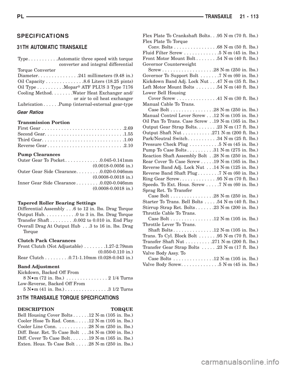
SPECIFICATIONS
31TH AUTOMATIC TRANSAXLE
Type...........Automatic three speed with torque
converter and integral differential
Torque Converter
Diameter...............241 millimeters (9.48 in.)
Oil Capacity..............8.6 Liters (18.25 pints)
OilType..........MopartATF PLUS 3 Type 7176
Cooling Method........Water Heat Exchanger and/
or air to oil heat exchanger
Lubrication......Pump (internal-external gear-type
Gear Ratios
Transmission Portion
First Gear..............................2.69
Second Gear.............................1.55
Third Gear..............................1.00
Reverse Gear............................2.10
Pump Clearances
Outer Gear To Pocket.............0.045-0.141mm
(0.0018-0.0056 in.)
Outer Gear Side Clearance.........0.020-0.046mm
(0.0008-0.0018 in.)
Inner Gear Side Clearance.........0.020-0.046mm
(0.0008-0.0018 in.)
Tapered Roller Bearing Settings
Differential Assembly . . .6 to 12 in. lbs. Drag Torque
Output Hub............0to3in.lbs. Drag Torque
Transfer Shaft.........0.002 to 0.010 in. End Play
Overall Drag At Output Hub . . .3 to 16 in. lbs. Drag
Torque
Clutch Pack Clearances
Front Clutch (Not Adjustable)........1.27-2.79mm
(0.050-0.110 in.)
Rear Clutch.........0.71-1.10mm (0.028-0.043 in.)
Band Adjustment
Kickdown, Backed Off From
8N²m (72 in. lbs.)...............21/4Turns
Low-Reverse, Backed Off From
5N²m (41 in. lbs.)................31/2Turns
31TH TRANSAXLE TORQUE SPECIFICATIONS
DESCRIPTION TORQUE
Bell Housing Cover Bolts......12N´m(105 in. lbs.)
Cooler Hose To Rad. Conn......12N´m(105 in. lbs.)
Cooler Line Conn............28N´m(250 in. lbs.)
Diff. Bear. Ret. To Case Bolt . . .34 N´m (300 in. lbs.)
Diff. Cover To Case Bolt.......19N´m(165 in. lbs.)
Exten. Hous. To Case Bolt.....28N´m(250 in. lbs.)Flex Plate To Crankshaft Bolts . . .95 N´m (70 ft. lbs.)
Flex Plate To Torque
Conv. Bolts................68N´m(50ft.lbs.)
Fluid Filter Screw.............5N´m(45in.lbs.)
Front Motor Mount Bolt........54N´m(40ft.lbs.)
Governor Counterweight
Screw...................28N´m(250 in. lbs.)
Governor To Support Bolt.......7N´m(60in.lbs.)
Kickdown Band Adj. Lock Nut . . .47 N´m (35 ft. lbs.)
Left Motor Mount Bolts........54N´m(40ft.lbs.)
Lower Bell Housing
Cover Screw...............41N´m(30ft.lbs.)
Manual Cable To Trans.
Case Bolt................28N´m(250 in. lbs.)
Manual Control Lever Screw . . .12 N´m (105 in. lbs.)
Oil Pan To Trans. Case Screw . .19 N´m (165 in. lbs.)
Output Gear Strap Bolts........23N´m(17ft.lbs.)
Output Shaft Nut...........271 N´m (200 ft. lbs.)
Park/Neutral Switch...........34N´m(25ft.lbs.)
Pressure Check Plug...........5N´m(45in.lbs.)
Pump To Case Bolts..........31N´m(275 in. lbs.)
Reaction Shaft Assembly Bolt . .28 N´m (250 in. lbs.)
Rear Cover To Case Screw.....19N´m(165 in. lbs.)
Reverse Band Adj. Lock Nut . . .14 N´m (125 in. lbs.)
Reverse Band Shaft Plug........7N´m(60in.lbs.)
Ring Gear Screw..............95N´m(70ft.lbs.)
Speedo. To Ext. Hous. Screw.....7N´m(60in.lbs.)
Sprag Ret. To Transfer
Case Bolt................28N´m(250 in. lbs.)
Starter To Trans. Bell Bolts.....54N´m(40ft.lbs.)
Stirrup Strap Ret. Bolts.......23N´m(200 in. lbs.)
Throttle Cable To Trans.
Case Bolt................12N´m(105 in. lbs.)
Throttle Lever To Trans.
Shaft Bolts...............12N´m(105 in. lbs.)
Trans. To Cyl. Block Bolt.......95N´m(70ft.lbs.)
Transfer Shaft Nut..........271 N´m (200 ft. lbs.)
Transfer Gear Strap Bolts......23N´m(17ft.lbs.)
Valve Body Assy. To
Case Bolts...............12N´m(105 in. lbs.)
Valve Body Screw..............5N´m(45in.lbs.)
PLTRANSAXLE 21 - 113
Page 1062 of 1200
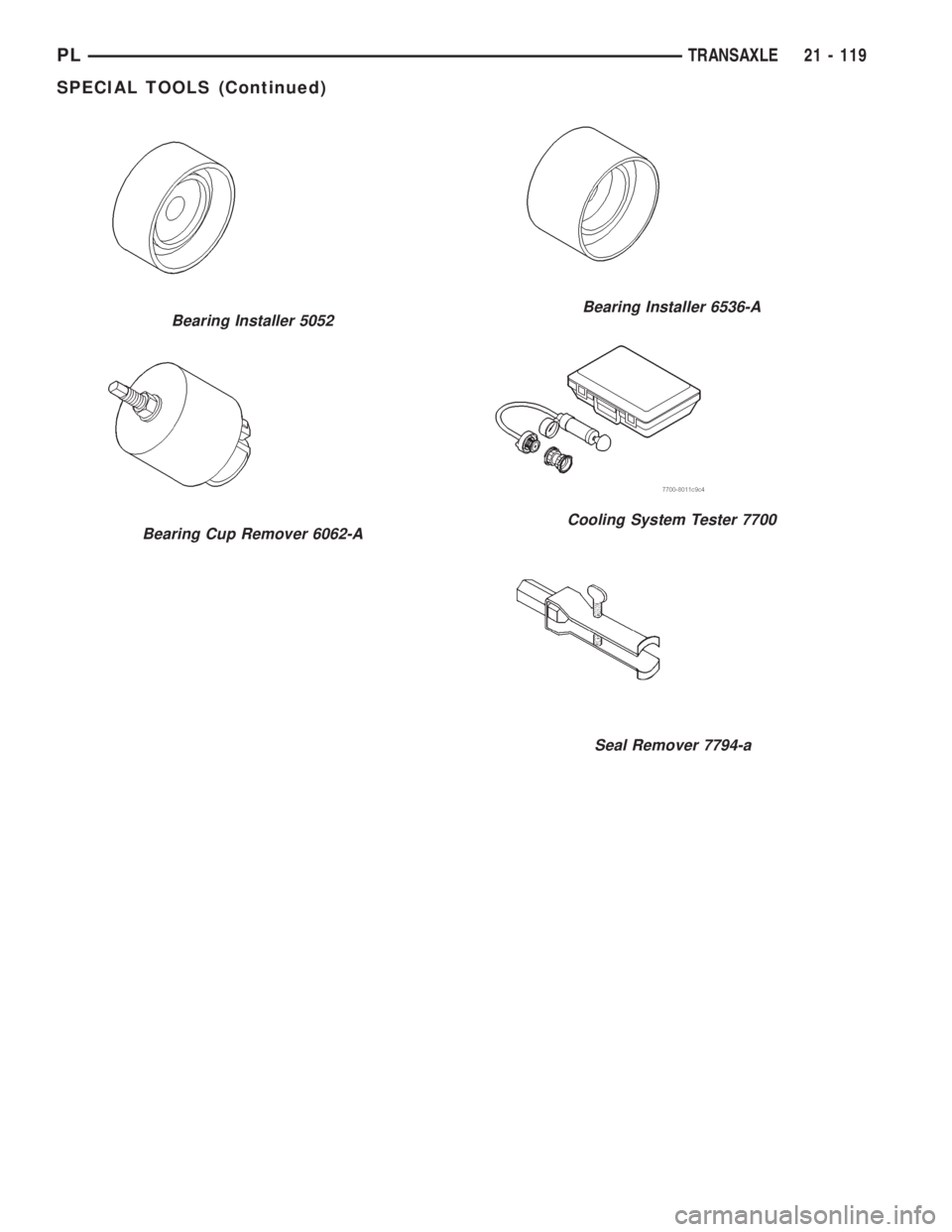
Seal Remover 7794-a
Bearing Installer 5052
Bearing Cup Remover 6062-A
Bearing Installer 6536-A
Cooling System Tester 7700
PLTRANSAXLE 21 - 119
SPECIAL TOOLS (Continued)
Page 1134 of 1200
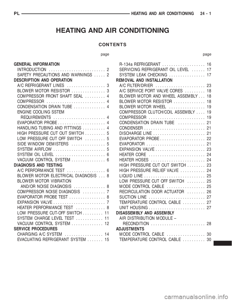
HEATING AND AIR CONDITIONING
CONTENTS
page page
GENERAL INFORMATION
INTRODUCTION......................... 2
SAFETY PRECAUTIONS AND WARNINGS..... 2
DESCRIPTION AND OPERATION
A/C REFRIGERANT LINES................. 3
BLOWER MOTOR RESISTOR............... 3
COMPRESSOR FRONT SHAFT SEAL......... 4
COMPRESSOR.......................... 4
CONDENSATION DRAIN TUBE.............. 4
ENGINE COOLING SSTEM
REQUIREMENTS....................... 4
EVAPORATOR PROBE..................... 4
HANDLING TUBING AND FITTINGS.......... 4
HIGH PRESSURE CUT OUT SWITCH......... 5
LOW PRESSURE CUT OFF SWITCH......... 5
SIDE WINDOW DEMISTERS............... 5
SYSTEM AIRFLOW....................... 5
SYSTEM OIL LEVEL...................... 6
VACUUM CONTROL SYSTEM............... 6
DIAGNOSIS AND TESTING
A/C PERFORMANCE TEST................. 6
BLOWER MOTOR ELECTRICAL DIAGNOSIS . . . 8
BLOWER MOTOR VIBRATION
AND/OR NOISE DIAGNOSIS.............. 8
COMPRESSOR NOISE DIAGNOSIS.......... 7
EVAPORATOR PROBE TEST................ 8
EXPANSION VALVE....................... 7
HEATER PERFORMANCE TEST............. 8
LOW PRESSURE CUT-OFF SWITCH......... 11
SYSTEM CHARGE LEVEL TEST............ 11
VACUUM CONTROL SYSTEM.............. 12
SERVICE PROCEDURES
CHARGING A/C SYSTEM................. 14
EVACUATING REFRIGERANT SYSTEM....... 15R-134a REFRIGERANT................... 16
SERVICING REFRIGERANT OIL LEVEL...... 17
SYSTEM LEAK CHECKING................ 17
REMOVAL AND INSTALLATION
A/C FILTER/DRIER...................... 23
A/C SERVICE PORT VALVE CORES......... 18
BLOWER MOTOR AND WHEEL ASSEMBLY . . . 18
BLOWER MOTOR RESISTOR.............. 18
BLOWER MOTOR WHEEL................ 19
COMPRESSOR CLUTCH/COIL ASSEMBLY.... 19
COMPRESSOR......................... 19
CONDENSATION DRAIN TUBE............ 21
CONDENSER........................... 21
DISCHARGE LINE....................... 21
EVAPORATOR PROBE.................... 22
EVAPORATOR.......................... 21
EXPANSION VALVE...................... 23
HEATER CORE......................... 24
HEATER HOSES........................ 24
HIGH PRESSURE CUT OUT SWITCH........ 23
HIGH PRESSURE RELIEF VALVE........... 24
LIQUID LINE........................... 25
LOW PRESSURE CUT OFF SWITCH........ 25
MODE CONTROL CABLE................. 25
RECIRCULATION DOOR ACTUATOR........ 26
SUCTION LINE......................... 27
TEMPERATURE CONTROL CABLE.......... 27
UNIT HOUSING......................... 27
DISASSEMBLY AND ASSEMBLY
AIR DISTRIBUTION MODULE ±
RECONDITION........................ 28
ADJUSTMENTS
MODE CONTROL CABLE................. 30
TEMPERATURE CONTROL CABLE.......... 30
PLHEATING AND AIR CONDITIONING 24 - 1