1999 DODGE NEON cooling
[x] Cancel search: coolingPage 217 of 1200
BELT TENSION GAUGE METHOD
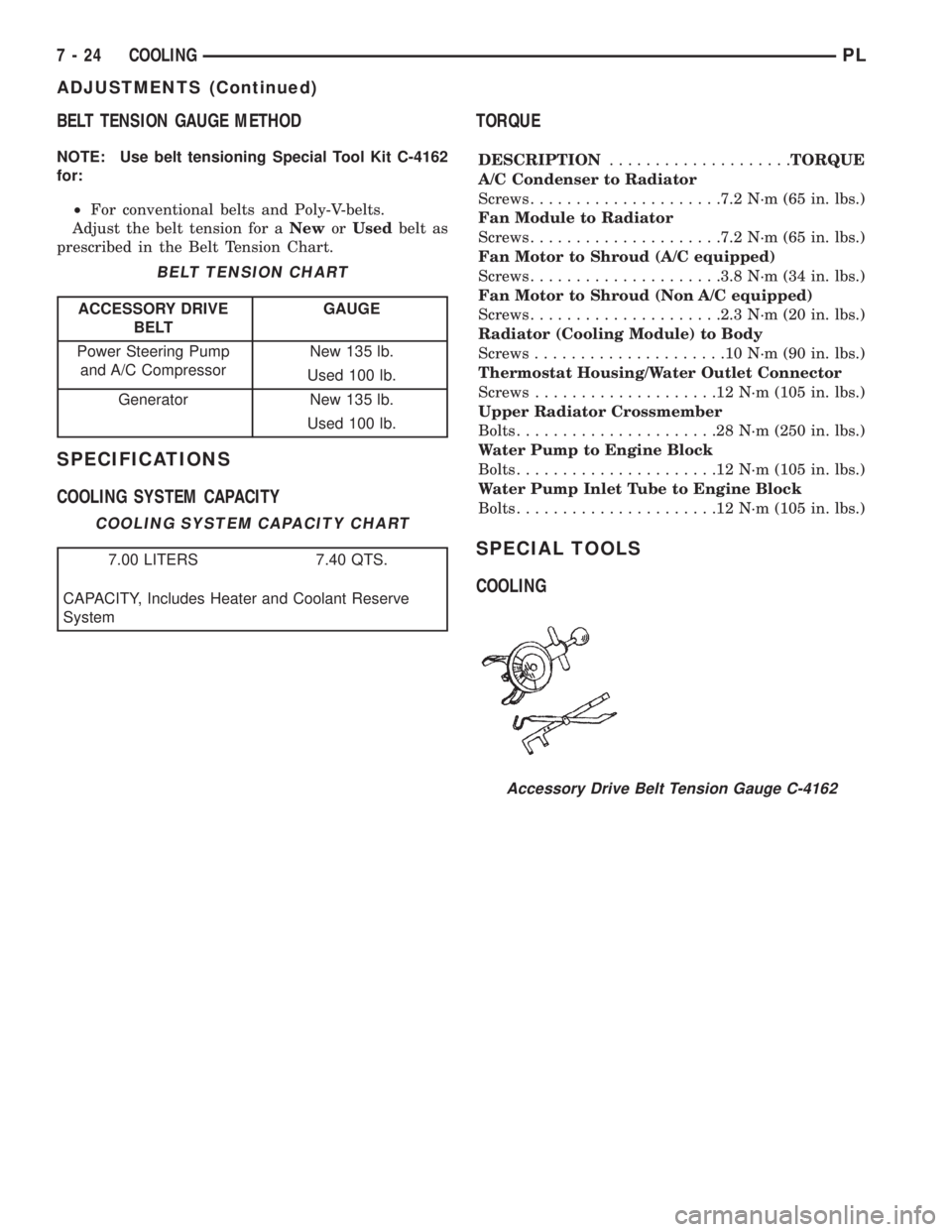
NOTE: Use belt tensioning Special Tool Kit C-4162
for:
²For conventional belts and Poly-V-belts.
Adjust the belt tension for aNeworUsedbelt as
prescribed in the Belt Tension Chart.
SPECIFICATIONS
COOLING SYSTEM CAPACITYTORQUE
DESCRIPTION....................TORQUE
A/C Condenser to Radiator
Screws.....................7.2 N´m (65 in. lbs.)
Fan Module to Radiator
Screws.....................7.2 N´m (65 in. lbs.)
Fan Motor to Shroud (A/C equipped)
Screws.....................3.8 N´m (34 in. lbs.)
Fan Motor to Shroud (Non A/C equipped)
Screws.....................2.3 N´m (20 in. lbs.)
Radiator (Cooling Module) to Body
Screws.....................10N´m(90in.lbs.)
Thermostat Housing/Water Outlet Connector
Screws....................12N´m(105 in. lbs.)
Upper Radiator Crossmember
Bolts......................28N´m(250 in. lbs.)
Water Pump to Engine Block
Bolts......................12N´m(105 in. lbs.)
Water Pump Inlet Tube to Engine Block
Bolts......................12N´m(105 in. lbs.)
SPECIAL TOOLS
COOLING
BELT TENSION CHART
ACCESSORY DRIVE
BELTGAUGE
Power Steering Pump
and A/C CompressorNew 135 lb.
Used 100 lb.
Generator New 135 lb.
Used 100 lb.
COOLING SYSTEM CAPACITY CHART
7.00 LITERS 7.40 QTS.
CAPACITY, Includes Heater and Coolant Reserve
System
Accessory Drive Belt Tension Gauge C-4162
7 - 24 COOLINGPL
ADJUSTMENTS (Continued)
Page 238 of 1200
Remember that an undercharged battery is often
caused by:
²Accessories being left on with the engine not
running
²A faulty or improperly adjusted switch that
allows a lamp to stay on. See Ignition-Off Draw Test
in Group 8A, Battery for more information.
The following procedures may be used to correct a
problem diagnosed as a charging system fault.
INSPECTION
(1) Inspect condition of battery cable terminals,
battery posts, connections at engine block, starter
solenoid and relay. They should be clean and tight.
Repair as required.
(2) Inspect all fuses in the fuseblock module and
Power Distribution Center (PDC) for tightness in
receptacles. They should be properly installed and
tight. Repair or replace as required.(3) Inspect the electrolyte level in the battery.
Replace battery if electrolyte level is low.
(4) Inspect generator mounting bolts for tightness.
Replace or tighten bolts if required. Refer to the Gen-
erator Removal/Installation section of this group for
torque specifications.
(5) Inspect generator drive belt condition and ten-
sion. Tighten or replace belt as required. Refer to
Belt Tension Specifications in Group 7, Cooling Sys-
tem.
(6) Inspect automatic belt tensioner (if equipped).
Refer to Group 7, Cooling System for information.
(7) Inspect connections at generator field, battery
output, and ground terminals. Also check ground con-
nection at engine. They should all be clean and tight.
Repair as required.
PLCHARGING SYSTEM 8C - 3
DIAGNOSIS AND TESTING (Continued)
Page 243 of 1200
performed at each (- ground) connection in this cir-
cuit to locate the excessive resistance.
(7) Testing (+ positive) circuitry:
(a) Touch the positive lead of voltmeter directly
to battery negativePOST.
(b) Touch the negative lead of voltmeter to the
ground terminal stud on the generator case (not
the terminal mounting nut). Voltage should be no
higher than 0.3 volts. If voltage is higher than 0.3
volts, touch test lead to terminal mounting stud
nut and then to the wiring connector. If voltage is
now below 0.3 volts, look for dirty, loose or poor
connection at this point. A voltage drop test may be
performed at each (+ positive) connection in this
circuit to locate the excessive resistance. This test
can also be performed between the generator case
and the engine. If test voltage is higher than 0.3
volts, check for corrosion at generator mounting
points or loose generator mounting.
CURRENT OUTPUT TEST
The current output test will determine if the
charging system can deliver its minimum test cur-
rent (amperage) output. Refer to the Specifications
section at the end of this group for minimum test
current (amperage) requirements.
The first part of this test will determine the com-
bined amperage output of both the generator and the
Electronic Voltage Regulator (EVR) circuitry.
PREPARATION
(1) Determine if any Diagnostic Trouble Codes
(DTC) exist. To determine a DTC, refer to On-Board
Diagnostics in this group. For repair, refer to the
appropriate Powertrain Diagnostic Procedures man-
ual.
(2) Before starting test, make sure battery is in
good condition and is fully-charged. See Group 8A,
Battery for more information.
(3) Check condition of battery cables at battery.
Clean if necessary.
(4) Perform the Voltage Drop Test. This will
ensure clean and tight generator/battery electrical
connections.
(5) Be sure the generator drive belt is properly
tensioned. Refer to Group 7, Cooling System for
information.
(6) A volt/amp tester equipped with both a battery
load control (carbon pile rheostat) and an inductive-
type pickup clamp (ammeter probe) will be used for
this test. Refer to operating instructions supplied
with tester. When using a tester equipped with an
inductive-type clamp, removal of wiring at the gener-
ator will not be necessary.
(7) Start the engine and allow it to reach operating
temperature.
(8) Shut engine off.(9) Turn off all electrical accessories and all vehicle
lighting.
(10) Connect the volt/amp tester leads to the bat-
tery. Be sure the carbon pile rheostat control is in the
OPEN or OFF position before connecting leads. See
Load Test in Group 8A, Battery for more information.
Also refer to the operating instructions supplied with
test equipment.
(11) Connect the inductive clamp (ammeter probe).
Refer to the operating instructions supplied with test
equipment.
(12) If volt/amp tester is not equipped with an
engine tachometer, connect a separate tachometer to
the engine.
TEST
(1) Perform the previous test Preparation.
(2) Fully engage the parking brake.
(3) Start engine.
(4) Bring engine speed to 2500 rpm.
(5) With engine speed held at 2500 rpm, slowly
adjust the rheostat control (load) on the tester to
obtain the highest amperage reading. Do not allow
voltage to drop below 12 volts. Record the reading.
This load test must be performed within 15 sec-
onds to prevent damage to test equipment.On
certain brands of test equipment, this load will be
applied automatically. Refer to the operating manual
supplied with test equipment.
(6) The ammeter reading must meet the Minimum
Test Amps specifications as displayed in the Genera-
tor Ratings chart. This can be found in the Specifica-
tions section at the end of this group. A label stating
a part reference number is attached to the generator
case. On some engines this label may be located on
the bottom of the case. Compare this reference num-
ber to the Generator Ratings chart.
(7) Rotate the load control to the OFF position.
(8) Continue holding engine speed at 2500. If EVR
circuitry is OK, amperage should drop below 15±20
amps. With all electrical accessories and vehicle
lighting off, this could take several minutes of engine
operation. If amperage did not drop, refer to the
appropriate Powertrain Diagnostic Procedures man-
ual for testing.
(9) Remove volt/amp tester.
If minimum amperage could not be met, refer to
the appropriate Powertrain Diagnostic Procedures
manual for testing.
BATTERY TEMPERATURE SENSOR
To perform a complete test of this sensor and its
circuitry, refer to the appropriate Powertrain Diag-
nostic Procedures manual. To test the sensor only,
refer to the following:
(1) The sensor is located under the battery and is
attached to the battery tray (Fig. 5). A two-wire pig-
8C - 8 CHARGING SYSTEMPL
DIAGNOSIS AND TESTING (Continued)
Page 245 of 1200
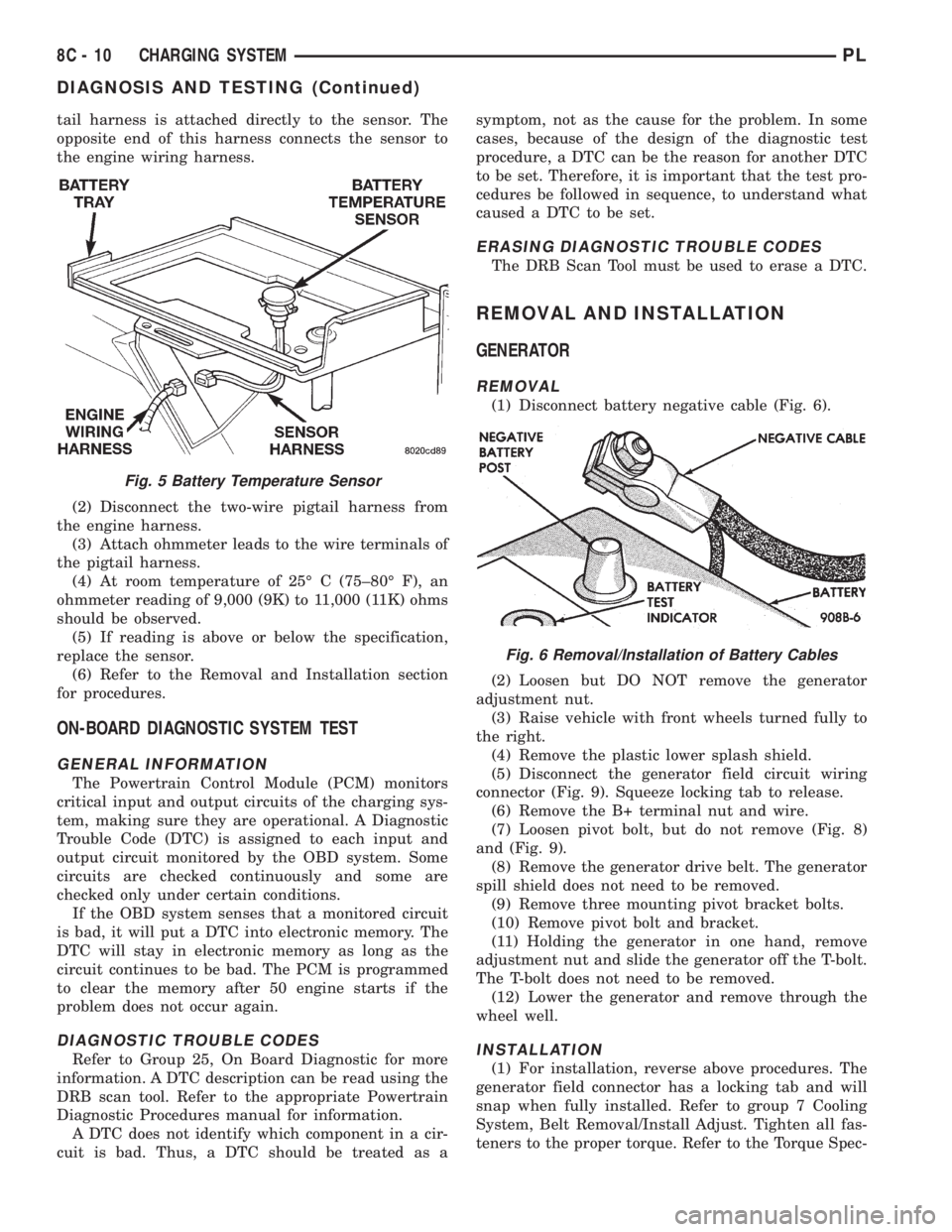
tail harness is attached directly to the sensor. The
opposite end of this harness connects the sensor to
the engine wiring harness.
(2) Disconnect the two-wire pigtail harness from
the engine harness.
(3) Attach ohmmeter leads to the wire terminals of
the pigtail harness.
(4) At room temperature of 25É C (75±80É F), an
ohmmeter reading of 9,000 (9K) to 11,000 (11K) ohms
should be observed.
(5) If reading is above or below the specification,
replace the sensor.
(6) Refer to the Removal and Installation section
for procedures.
ON-BOARD DIAGNOSTIC SYSTEM TEST
GENERAL INFORMATION
The Powertrain Control Module (PCM) monitors
critical input and output circuits of the charging sys-
tem, making sure they are operational. A Diagnostic
Trouble Code (DTC) is assigned to each input and
output circuit monitored by the OBD system. Some
circuits are checked continuously and some are
checked only under certain conditions.
If the OBD system senses that a monitored circuit
is bad, it will put a DTC into electronic memory. The
DTC will stay in electronic memory as long as the
circuit continues to be bad. The PCM is programmed
to clear the memory after 50 engine starts if the
problem does not occur again.
DIAGNOSTIC TROUBLE CODES
Refer to Group 25, On Board Diagnostic for more
information. A DTC description can be read using the
DRB scan tool. Refer to the appropriate Powertrain
Diagnostic Procedures manual for information.
A DTC does not identify which component in a cir-
cuit is bad. Thus, a DTC should be treated as asymptom, not as the cause for the problem. In some
cases, because of the design of the diagnostic test
procedure, a DTC can be the reason for another DTC
to be set. Therefore, it is important that the test pro-
cedures be followed in sequence, to understand what
caused a DTC to be set.
ERASING DIAGNOSTIC TROUBLE CODES
The DRB Scan Tool must be used to erase a DTC.
REMOVAL AND INSTALLATION
GENERATOR
REMOVAL
(1) Disconnect battery negative cable (Fig. 6).
(2) Loosen but DO NOT remove the generator
adjustment nut.
(3) Raise vehicle with front wheels turned fully to
the right.
(4) Remove the plastic lower splash shield.
(5) Disconnect the generator field circuit wiring
connector (Fig. 9). Squeeze locking tab to release.
(6) Remove the B+ terminal nut and wire.
(7) Loosen pivot bolt, but do not remove (Fig. 8)
and (Fig. 9).
(8) Remove the generator drive belt. The generator
spill shield does not need to be removed.
(9) Remove three mounting pivot bracket bolts.
(10) Remove pivot bolt and bracket.
(11) Holding the generator in one hand, remove
adjustment nut and slide the generator off the T-bolt.
The T-bolt does not need to be removed.
(12) Lower the generator and remove through the
wheel well.
INSTALLATION
(1) For installation, reverse above procedures. The
generator field connector has a locking tab and will
snap when fully installed. Refer to group 7 Cooling
System, Belt Removal/Install Adjust. Tighten all fas-
teners to the proper torque. Refer to the Torque Spec-
Fig. 5 Battery Temperature Sensor
Fig. 6 Removal/Installation of Battery Cables
8C - 10 CHARGING SYSTEMPL
DIAGNOSIS AND TESTING (Continued)
Page 261 of 1200
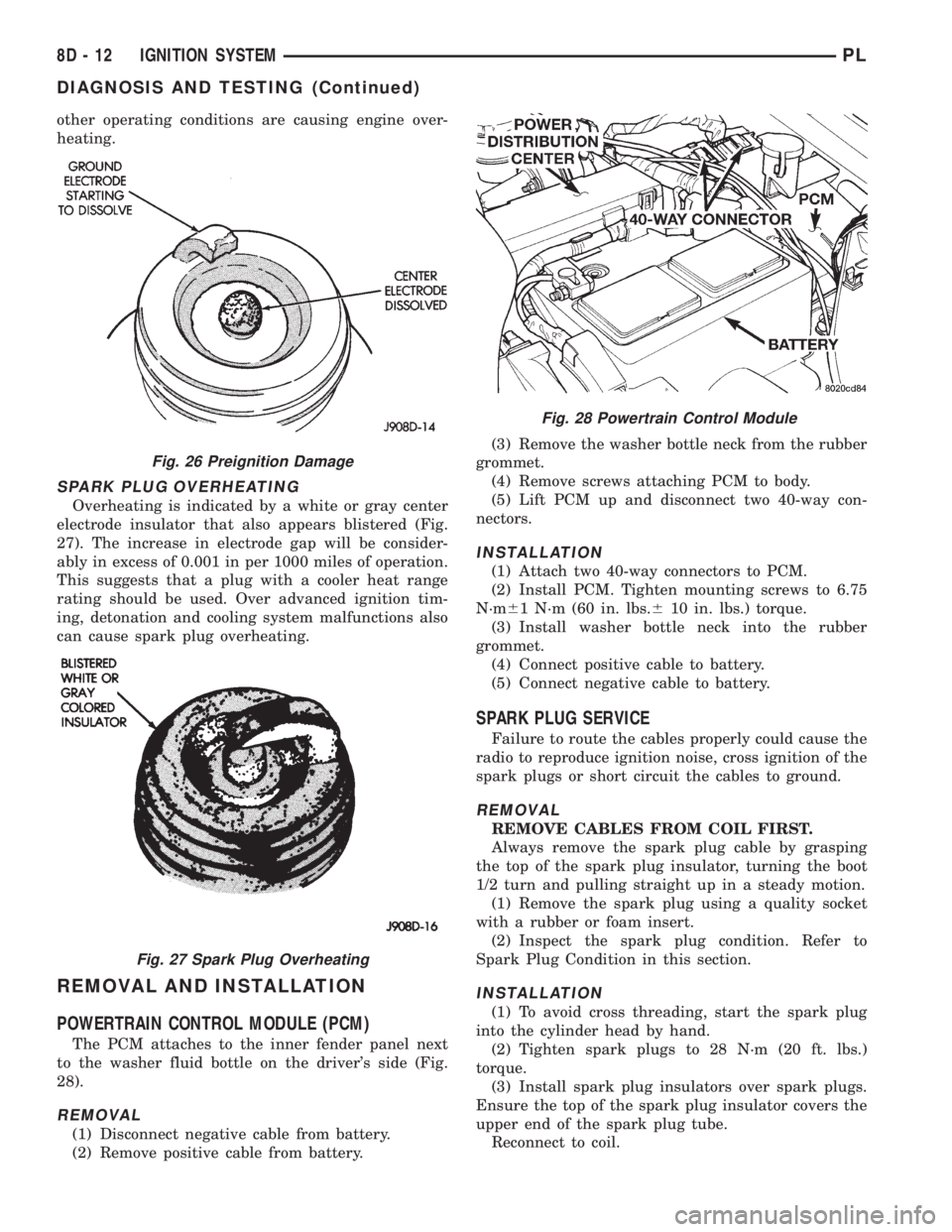
other operating conditions are causing engine over-
heating.
SPARK PLUG OVERHEATING
Overheating is indicated by a white or gray center
electrode insulator that also appears blistered (Fig.
27). The increase in electrode gap will be consider-
ably in excess of 0.001 in per 1000 miles of operation.
This suggests that a plug with a cooler heat range
rating should be used. Over advanced ignition tim-
ing, detonation and cooling system malfunctions also
can cause spark plug overheating.
REMOVAL AND INSTALLATION
POWERTRAIN CONTROL MODULE (PCM)
The PCM attaches to the inner fender panel next
to the washer fluid bottle on the driver's side (Fig.
28).
REMOVAL
(1) Disconnect negative cable from battery.
(2) Remove positive cable from battery.(3) Remove the washer bottle neck from the rubber
grommet.
(4) Remove screws attaching PCM to body.
(5) Lift PCM up and disconnect two 40-way con-
nectors.
INSTALLATION
(1) Attach two 40-way connectors to PCM.
(2) Install PCM. Tighten mounting screws to 6.75
N´m61 N´m (60 in. lbs.610 in. lbs.) torque.
(3) Install washer bottle neck into the rubber
grommet.
(4) Connect positive cable to battery.
(5) Connect negative cable to battery.
SPARK PLUG SERVICE
Failure to route the cables properly could cause the
radio to reproduce ignition noise, cross ignition of the
spark plugs or short circuit the cables to ground.
REMOVAL
REMOVE CABLES FROM COIL FIRST.
Always remove the spark plug cable by grasping
the top of the spark plug insulator, turning the boot
1/2 turn and pulling straight up in a steady motion.
(1) Remove the spark plug using a quality socket
with a rubber or foam insert.
(2) Inspect the spark plug condition. Refer to
Spark Plug Condition in this section.
INSTALLATION
(1) To avoid cross threading, start the spark plug
into the cylinder head by hand.
(2) Tighten spark plugs to 28 N´m (20 ft. lbs.)
torque.
(3) Install spark plug insulators over spark plugs.
Ensure the top of the spark plug insulator covers the
upper end of the spark plug tube.
Reconnect to coil.
Fig. 26 Preignition Damage
Fig. 27 Spark Plug Overheating
Fig. 28 Powertrain Control Module
8D - 12 IGNITION SYSTEMPL
DIAGNOSIS AND TESTING (Continued)
Page 264 of 1200

(1) Install target magnet in end of camshaft.
Tighten mounting screw to 3 N´m (30 in. lbs.) torque.
(2) Install camshaft position sensor. Tighten sensor
mounting screws to 9 N´m (80 in. lbs.) torque.
(3) Carefully attach electrical connector to cam-
shaft position sensor. Installation at an angle may
damage the sensor pins.
(4) Install filtered air tube. Tighten clamps to 3
N´m61 (25 in. lbs.65) torque.
CRANKSHAFT POSITION SENSOR
The crankshaft position sensor mounts to the
engine block behind the generator, just above the oil
filter (Fig. 37).
REMOVAL
(1) Disconnect electrical connector from crankshaft
position sensor.
(2) Remove sensor mounting screw. Remove sensor.
INSTALLATION
Reverse procedure for installation.
COMBINATION ENGINE COOLANT TEMPERATURE
SENSORÐSOHC
The combination engine coolant sensor is located at
the rear of the cylinder head next to the camshaft
position sensor (Fig. 38). New sensors have sealant
applied to the threads.
REMOVAL
(1) With the engine cold, drain the cooling system
until coolant level drops below sensor. Refer to Group
7, Cooling System.
(2) Disconnect coolant sensor electrical connector.
(3) Remove coolant sensor
INSTALLATION
(1) Install coolant sensor. Tighten sensor to 18.6
N´m (165 in. lbs.) torque.
(2) Attach electrical connector to sensor.
(3) Fill cooling system. Refer to Group 7, Cooling
System.
COMBINATION ENGINE COOLANT TEMPERATURE
SENSORÐDOHC
The coolant sensor threads into the intake mani-
fold next to the thermostat housing (Fig. 39). New
sensors have sealant applied to the threads.
REMOVAL
(1) With the engine cold, drain coolant until level
drops below cylinder head. Refer to Group 7, Cooling
System.
(2) Disconnect coolant sensor electrical connector.
(3) Remove coolant sensor.
INSTALLATION
(1) Install coolant sensor. Tighten sensor to 18.6
N´m (165 in. lbs.) torque.
(2) Attach electrical connector to sensor.
(3) Fill cooling system. Refer to Group 7, Cooling
System.
Fig. 36 Target Magnet Installation
Fig. 37 Crankshaft Position Sensor
Fig. 38 Engine Coolant Temperature Sensor
PLIGNITION SYSTEM 8D - 15
REMOVAL AND INSTALLATION (Continued)
Page 715 of 1200

assure gasket rails are flat. Flatten rails with a ham-
mer on a heavy steel plate if required. Gasket sur-
faces must be free of oil and dirt. Make sure old
gasket material is removed from blind attaching
holes.
FORM-IN-PLACE GASKET APPLICATION
Assembling parts using a form-in-place gasket
requires care but it's easier then using precut gas-
kets.
MopartGasket Maker material should be applied
sparingly 1 mm (0.040 inch.) diameter or less of seal-
ant to one gasket surface. Be certain the material
surrounds each mounting hole. Excess material can
easily be wiped off. Components should be torqued in
place within 15 minutes. The use of a locating dowel
is recommended during assembly to prevent smear-
ing material off the location.
The MopartSilicone Rubber Adhesive Sealant gas-
ket material or equivalent should be applied in a con-
tinuous bead approximately 3 mm (0.120 inch) in
diameter. All mounting holes must be circled. For
corner sealing, a 3.17 or 6.35 mm (1/8 or 1/4 inch.)
drop is placed in the center of the gasket contact
area. Uncured sealant may be removed with a shop
towel. Components should be torqued in place while
the sealant is still wet to the touch (within 10 min-
utes). The usage of a locating dowel is recommended
during assembly to prevent smearing material off the
location.
CRANKSHAFT SPROCKET BOLT ACCESS PLUG
An Access plug is located in the right inner fender
shield. Remove the plug and insert the proper size
socket, extension and ratchet, when crankshaft rota-
tion is necessary.
ENGINE CORE PLUGS
REMOVAL
Using a blunt tool such as a drift or a screwdriver
and a hammer, strike the bottom edge of the cup
plug (Fig. 1). With the cup plug rotated, grasp firmly
with pliers or other suitable tool and remove plug
(Fig. 1).
CAUTION: Do not drive cup plug into the casting
as restricted cooling can result and cause serious
engine problems.
INSTALLATION
Thoroughly remove all rust and clean inside of cup
plug hole in cylinder block or head. Be sure to
remove old sealer. Lightly coat inside of cup plug hole
with sealer. Make certain the new plug is cleaned of
all oil or grease. Using proper drive plug, drive plug
into hole so that the sharp edge of the plug is atleast 0.5 mm (0.020 inch.) inside the lead in chamfer
(Fig. 1).
It is in not necessary to wait for curing of the seal-
ant. The cooling system can be refilled and the vehi-
cle placed in service immediately.
ENGINE PERFORMANCE
If a loss of performance is noticed, timing belt or
chain may have skipped one or two teeth. Camshaft
and crankshaft timing should be checked. Refer to
Group 9, Engine Timing belt or chain installation.
It is important that the vehicle is operating to its
optimum performance level to maintain fuel economy
and lowest vehicle emissions. If vehicle is not operat-
ing to these standards, refer to Engine Diagnosis out-
lined is this section. The following procedures can
assist in achieving the proper engine diagnosis.
(1) Test cranking amperage draw. Refer to Group
8B, Starting.
(2) Check intake manifold for vacuum leaks.
(3) Perform cylinder compression pressure test.
Refer to Engine Diagnosis, outlined in this section.
(4) Clean or replace spark plugs as necessary and
adjust gap as specified in Group 8D, Ignition System.
Tighten to specifications.
(5) Test resistance of spark plug cables. Refer to
Group 8D, Ignition System.
(6) Test ignition coils primary and secondary resis-
tance. Replace parts as necessary. Refer to Group 8D,
Ignition System.
(7) Check fuel pump pressure at idle and different
RPM ranges. Refer to Group 14, Fuel System for
Specifications.
(8) The air filter elements should be replaced as
specified in Group 0, Lubrication and Maintenance.
(9) Inspect crankcase ventilation system as out-
lined in Group 25, Emission Control Systems.
(10) Road test vehicle as a final test.
Fig. 1 Core Hole Plug Removal
9 - 2 ENGINEPL
GENERAL INFORMATION (Continued)
Page 721 of 1200

cause of low compression unless some malfunc-
tion is present.
(11) Clean or replace spark plugs as necessary
and adjust gap as specified in Group 8, Electrical.
Tighten to specifications.
(12) Test resistance of spark plug cables. Refer to
Group 8, Electrical Ignition System Secondary Cir-
cuit Inspection.
(13) Test coil output voltage, primary and second-
ary resistance. Replace parts as necessary. Refer to
Group 8, Electrical Ignition System.
(14) Check fuel pump pressure at idle and differ-
ent RPM ranges. Refer to Group 14, Fuel System for
Specifications.
(15) The air filter elements should be replaced as
specified in Group 0, Lubrication and Maintenance,.
(16) Inspect crankcase ventilation system as out
lined in Group 0, Lubrication and Maintenance. For
emission controls see Group 25, Emission Controls
for service procedures.
(17) Inspect and adjust accessory belt drives refer-
ring to Group 7, Cooling System, Accessory Drive
Belts for proper adjustments.
(18) Road test vehicle as a final test.
CYLINDER COMBUSTION PRESSURE LEAKAGE
TEST
The combustion pressure leakage test provides an
accurate means for determining engine condition.
Combustion pressure leakage testing will detect:
²Exhaust and intake valve leaks (improper seat-
ing).
²Leaks between adjacent cylinders or into water
jacket.
²Any causes for combustion/compression pressure
loss.
WARNING: DO NOT REMOVE THE RADIATOR CAP
WITH THE SYSTEM HOT AND UNDER PRESSURE
BECAUSE SERIOUS BURNS FROM COOLANT CAN
OCCUR.
Check the coolant level and fill as required. DO
NOT install the radiator cap.
Start and operate the engine until it attains nor-
mal operating temperature, then turn the engine
OFF.
Clean spark plug recesses with compressed air.
Remove the spark plugs.
Remove the oil filler cap.
Remove the air cleaner.
Calibrate the tester according to the manufactur-
er's instructions. The shop air source for testing
should maintain 483 kPa (70 psi) minimum, 1 379
kPa (200 psi) maximum and 552 kPa (80 psi) recom-
mended.Perform the test procedures on each cylinder
according to the tester manufacturer's instructions.
While testing, listen for pressurized air escaping
through the throttle body, tailpipe and oil filler cap
opening. Check for bubbles in the radiator coolant.
All gauge pressure indications should be equal,
with no more than 25% leakage.
FOR EXAMPLE:At 552 kPa (80 psi) input pres-
sure, a minimum of 414 kPa (60 psi) should be main-
tained in the cylinder.
LASH ADJUSTER (TAPPET) NOISE DIAGNOSIS
A tappet-like noise may be produced from several
items. Check the following items.
(1) Engine oil level too high or too low. This may
cause aerated oil to enter the adjusters and cause
them to be spongy.
(2) Insufficient running time after rebuilding cylin-
der head. Low speed running up to 1 hour may be
required.
(3) During this time, turn engine off and let set for
a few minutes before restarting. Repeat this several
times after engine has reached normal operating
temperature.
(4) Low oil pressure.
(5) The oil restrictor pressed into the vertical oil
passage to the cylinder head is plugged with debris.
(6) Air ingested into oil due to broken or cracked
oil pump pick up.
(7) Worn valve guides.
(8) Rocker arm ears contacting valve spring
retainer.
(9) Rocker arm loose, adjuster stuck or at maxi-
mum extension and still leaves lash in the system.
(10) Faulty lash adjuster.
a. Check lash adjusters for sponginess while
installed in cylinder head. Depress part of rocker
arm over adjuster. Normal adjusters should feel very
firm. Spongy adjusters can be bottomed out easily.
b. Remove suspected rocker arms (sohc) or lash
adjuster (dohc) and replace.
INSPECTION (ENGINE OIL LEAKS IN GENERAL)
Begin with a through visual inspection of the
engine, particularly at the area of the suspected leak.
If an oil leak source is not readily identifiable, the
following steps should be followed:
(1) Do not clean or degrease the engine at this
time because some solvents may cause rubber to
swell, temporarily stopping the leak.
(2) Add an oil soluble dye (use as recommended by
manufacturer). Start the engine and let idle for
approximately 15 minutes. Check the oil dipstick to
make sure the dye is thoroughly mixed as indicated
with a bright yellow color under a black light.
9 - 8 ENGINEPL
DIAGNOSIS AND TESTING (Continued)