1999 DODGE NEON turn signal
[x] Cancel search: turn signalPage 362 of 1200
(5) Lift module and disconnect the airbag and horn
wire connectors.
(6) Remove steering wheel retaining nut.
(7) Remove the steering wheel with a steering
wheel puller. While removing the steering wheel take
care to feed the wires gently through the holes in the
clockspring armature.
INSTALLATION
(1) Confirm that:
²The steering wheel position is a half turn (180
degrees) to the right (clockwise)
²The column is locked with the ignition cylinder
lock.
²Check that the turn signal stalk is in the neu-
tral position
(2) Install the steering wheel ensuring the flats on
hub align with the clockspring. Pull the horn lead,
airbag and speed control leads through the larger
slot. Ensure leads do not get pinched under the steer-
ing wheel.
(3) Install the steering wheel retaining nut, and
tighten it to 61 N´m (45 ft. lbs.) torque.
(4) Install the airbag module. Refer to Driver Air-
bag Module Removal and Installation for proper pro-
cedures.
(5) Do not connect the battery negative cable.
Refer to Diagnosis and Testing for Airbag System
Test procedures.
ADJUSTMENTS
CLOCKSPRING CENTERING PROCEDURE
If the rotating tape within the clockspring is not
positioned properly with the steering wheel and the
front wheels, the clockspring may fail during use.
The following procedure MUST BE USED to center
the clockspring if:²The clockspring is not known to be properly
positioned
²The front wheels were moved
²The steering wheel was moved from the half
turn (180 degrees) to the right (clockwise) position.
WARNING: DISCONNECT AND ISOLATE THE BAT-
TERY NEGATIVE (GROUND) CABLE BEFORE
BEGINNING ANY AIRBAG SYSTEM COMPONENT
REMOVAL OR INSTALLATION PROCEDURE. THIS
WILL DISABLE THE AIRBAG SYSTEM. FAILURE TO
DISCONNECT BATTERY COULD RESULT IN ACCI-
DENTAL AIRBAG DEPLOYMENT AND POSSIBLE
PERSONAL INJURY.
ALLOW SYSTEM CAPACITOR TO DISCHARGE
FOR 2 MINUTES BEFORE REMOVING ANY AIRBAG
COMPONENTS.
(1) Remove clockspring, refer to Clockspring
Removal.
(2) Rotate the clockspring rotor in the CLOCK-
WISE DIRECTION to the end of travel. Do not apply
excessive torque.
(3) From the end of travel, rotate the rotor two full
turns and a half in the counterclockwise direction.
The horn wire and the squib wire should end up at
the bottom. If not, rotate the rotor counter clockwise
until the wires are properly orientated, but not more
than half turn (180 degrees). Engage clockspring
locking mechanism.
(4) For installation, refer to Clockspring Installa-
tion
(5) Do not connect battery negative cable. Refer to
Diagnosis and Testing for Airbag System Test
procedures.
PLRESTRAINT SYSTEM 8M - 11
REMOVAL AND INSTALLATION (Continued)
Page 376 of 1200
IMMOBILIZER SYSTEM
CONTENTS
page page
DESCRIPTION AND OPERATION
IMMOBILIZER RECEIVER................ 1
IMMOBILIZER SYSTEM.................. 1
IMMOBILIZER TRANSMITTER............. 2
POWER-UP MODE...................... 2
DIAGNOSIS AND TESTING
IMMOBILIZER DIAGNOSIS............... 2SERVICE PROCEDURES
VEHICLE IMMOBILIZER SYSTEM.......... 3
REMOVAL AND INSTALLATION
IMMOBILIZER RECEIVER................ 3
DESCRIPTION AND OPERATION
IMMOBILIZER SYSTEM
The Immobilizer system includes the following
unique items:
²An immobilizer module receiver that controls
system operation and also controls the RKE and Illu-
minated entry systems, if equipped.
²An encoded Crankshaft Position Sensor for the
ignition system. The Immobilizer module decodes the
signal from the crankshaft so the PCM can recognize
it as a valid Crankshaft Position Sensor signal, and
allow the engine to run.
²A wiring harness that interconnects the crank-
shaft sensor, the immobilizer receiver, and the PCM.
²Two key fob transmitters.
The Immobilizer System prevents unauthorized
operation of the vehicle by disabling the engine and
starter. The system will NOT allow the vehicle to
start unless the UNLOCK button on the RKE trans-
mitter is pressed. The system will be activated after
turning the ignition switch to the OFF position and
using one of the following methods.
(1) Press the LOCK button on the RKE transmit-
ter.
(2) LOCK the doors by pressing a power lock but-
ton switch.
(3) LOCK the driver or passenger door using the
key.
²The Security light will flash, for about 16 sec-
onds, indicating that the engine and starter will be
disabled.
²The Security light remaining on, indicates the
system is not operational.
²The Immobilizer will activate automatically
within 10 minutes of the ignition switch being in the
OFF position, whether the vehicle has been locked or
unlocked.²An attempt to start the vehicle without pressing
the UNLOCK button on the RKE transmitter will
result in a warning chime and the Security light
flashing.
NOTE: The ignition switch must be in the OFF posi-
tion in order for the system to be activated, whether
the doors are closed or not.
IMMOBILIZER RECEIVER
The immobilizer receiver is programmed to
respond to the Lock and Unlock radio signals issued
by the immobilizer transmitters. The receiver will
only respond to the radio signals of transmitters (up
to four) whose vehicle access codes have been stored
in the receiver's electronic memory. The receiver is
programmed at the assembly plant with the vehicle
access codes of the two transmitters that are shipped
with the vehicle.
The immobilizer receiver also has a central pro-
cessing unit, which contains the immobilizer system
logic. The programming in the immobilizer receiver
allows the system to learn and retain transmitter
vehicle access codes, as well as to communicate with
the Powertrain Control Module (PCM) and/or the
DRB scan tool on the Chrysler Collision Detection
(CCD) data bus network.
The CCD data bus network allows the sharing of
sensor information. This helps to reduce wiring har-
ness complexity, reduce internal controller hardware,
and reduce component sensor current loads. At the
same time, the CCD data bus network provides
increased reliability and enhanced diagnostic capabil-
ities.
Each immobilizer transmitter has a different vehi-
cle access code, which must be programmed into the
memory of the immobilizer receiver in the vehicle in
order to operate the immobilizer system. A DRB scan
tool must be used to program new or additional
PLIMMOBILIZER SYSTEM 8Q - 1
Page 390 of 1200
CHIME WARNING/REMINDER SYSTEM
CONTENTS
page page
GENERAL INFORMATION
INTRODUCTION......................... 1
DIAGNOSIS AND TESTING
CHIME SYSTEM CONDITIONS.............. 1
FASTEN SEAT BELTS..................... 1
HEADLAMPS LEFT ON.................... 1KEY LEFT IN IGNITION SWITCH............ 1
REMOVAL AND INSTALLATION
CHIME................................. 2
HEADLAMP SWITCH..................... 2
KEY-IN SWITCH......................... 2
SEAT BELT BUCKLE...................... 2
GENERAL INFORMATION
INTRODUCTION
WARNING: ON VEHICLES EQUIPPED WITH AN
AIRBAG, REFER TO THE AIRBAG PORTION OF
THIS SECTION FOR STEERING WHEEL OR SWITCH
REMOVAL AND INSTALLATION PROCEDURES.
The seat belt reminder system uses both visual
and audible signals. A combined seat belt and key
reminder chime with a red light on the instrument
panel.
The system will always illuminate the seat belt
reminder lamp for four to eight seconds when the
ignition switch is turned to the ON position. The
CHIME will sound during the same time interval if
the driver's seat belt is not fastened. Passenger belts
are not connected to the system. The chime will acti-
vate if the drivers door is opened and:
²The key is in the ignition switch, with the igni-
tion switch in either the OFF or accessory (ACC)
position
²The head lamps are ON.
The chime is part of the instrument cluster.
NOTE: This group covers both Left-Hand Drive
(LHD) and Right-Hand Drive (RHD) versions of this
model. Whenever required and feasible, the RHD
versions of affected vehicle components have been
constructed as mirror-image of the LHD versions.
While most of the illustrations used in this group
represent only the LHD version, the diagnostic and
service procedures outlined can generally be
applied to either version. Exceptions to this rule
have been clearly identified as LHD, RHD, or Export
if a special illustration or procedure is required.
DIAGNOSIS AND TESTING
FASTEN SEAT BELTS
To test the fasten seat belts function, turn the igni-
tion switch to the ON position with the driver's seat
belt unbuckled and fully retracted. The seat belt
warning lamp should light for four to eight seconds
and the tone should sound three to five times.
HEADLAMPS LEFT ON
To test the headlamps left on function:
²Turn headlamps
²Driver's door open
²Key removed from the ignition switch
Chime should sound until headlamps are turned
off or driver's door is closed.
KEY LEFT IN IGNITION SWITCH
To test the key left in ignition function, insert key
into the ignition and open driver's door. Chime
should sound until key is removed from ignition or
driver's door is closed.
CHIME SYSTEM CONDITIONS
The cluster harness connector, J1 is car right and
the J2 is car left.
NO TONE WHEN IGNITION SWITCH IS
TURNED ON AND DRIVERS SEAT BELT IS
UNBUCKLED
(1) Using an ohmmeter, with the seat belt fully
retracted, check for continuity to ground at Pin 4 of
the J1 wire harness connector (Fig. 1). If OK, go to
step 2. If not OK, repair as necessary .
(2) Check for continuity to ground at Pin 8 of the
J1 wire harness connector. If OK, go to Step 3. If not
OK, repair as necessary.
(3) Using voltmeter, check for battery feed at Pin 6
of the J1 wire harness connector. Check for ignition
feed at Pin 5 of the J1 wire harness connector. If not
OK, repair as necessary.
PLCHIME WARNING/REMINDER SYSTEM 8U - 1
Page 392 of 1200
WIRING DIAGRAMS
CONTENTS
page page
AIR CONDITIONING-HEATER.......... 8W-42-1
AIRBAG SYSTEM................... 8W-43-1
ANTI-LOCK BRAKES................. 8W-35-1
AUDIO SYSTEMS................... 8W-47-1
CHARGING SYSTEM................. 8W-20-1
COMPONENT INDEX................. 8W-02-1
CONNECTOR/GROUND LOCATIONS..... 8W-90-1
CONNECTOR PIN-OUTS.............. 8W-80-1
FRONT LIGHTING................... 8W-50-1
FUEL/IGNITION SYSTEMS............ 8W-30-1
FUSE BLOCK....................... 8W-11-1
GENERAL INFORMATION............. 8W-01-1
GROUND DISTRIBUTION............. 8W-15-1
HORN/CIGAR LIGHTER............... 8W-41-1INSTRUMENT CLUSTER.............. 8W-40-1
INTERIOR LIGHTING................. 8W-44-1
POWER DISTRIBUTION.............. 8W-10-1
POWER DOOR LOCKS............... 8W-61-1
POWER MIRRORS.................. 8W-62-1
POWER SUNROOF.................. 8W-64-1
POWER WINDOWS.................. 8W-60-1
REAR LIGHTING.................... 8W-51-1
REAR WINDOW DEFOGGER........... 8W-48-1
SPLICE INFORMATION............... 8W-70-1
SPLICE LOCATIONS................. 8W-95-1
STARTING SYSTEM................. 8W-21-1
TURN SIGNALS..................... 8W-52-1
WIPERS........................... 8W-53-1
PLWIRING DIAGRAMS 8W - 1
Page 410 of 1200

8W-02 COMPONENT INDEX
Component Page
A/C Compressor Clutch..................8W-42
A/C Compressor Clutch Relay.............8W-42
A/C Cycling Switch.....................8W-42
A/C Heater Blower Motor................8W-42
A/C Heater Control.....................8W-42
A/C Pressure Switches...................8W-42
ABS Warning Lamp Relay................8W-35
Airbag Control Module...................8W-43
Airbags..............................8W-43
Antenna..............................8W-47
Ash Receiver Lamp.....................8W-44
Automatic Shut Down Relay..............8W-30
Back-Up Lamp Switch...................8W-51
Back-Up Lamps........................8W-51
Battery..............................8W-20
Battery Temperature Sensor..............8W-30
Blower Motor Resistor Block..............8W-42
Brake Warning Lamp Switch...........8W-40, 50
Camshaft Position Sensor................8W-30
Center High Mounted Stop Lamp..........8W-51
Cigar Lighter Relay.....................8W-41
Cigar Lighter/Power Outlet...............8W-41
Circuit Breakers.......................8W-11
Clockspring.....................8W-30, 41, 61
Clutch Pedal Position Switch...........8W-10, 21
Combination Flasher....................8W-52
Controller Anti-Lock Brake...............8W-35
Crankshaft Position Sensor...............8W-30
Data Link Connector....................8W-30
Daytime Running Lamp Module...........8W-50
Diode No. 1........................8W-15, 42
Diode No. 2......................8W-10, 11, 44
Diode No. 3......................8W-11,44,70
Dome Lamp...........................8W-44
Door Ajar Switches.....................8W-44
Door Jamb Switches....................8W-44
Door Lock Motors......................8W-61
Door Lock Motors......................8W-61
Door Lock Switches.....................8W-61
Duty Cycle Evap/Purge Solenoid...........8W-30
EGR Transducer Solenoid................8W-30
Engine Coolant Temperature Sensor........8W-30
Engine Oil Pressure Switch...............8W-40
Engine Starter Motor....................8W-21
Engine Starter Motor Relay...............8W-21
Fog Lamp Relays....................8W-50, 51
Fog Lamp Switches..................8W-50, 51
Fog Lamps.........................8W-50, 51
Fuel Injectors..........................8W-30
Fuel Pump Module.....................8W-30
Fuel Pump Relay.......................8W-30
Fuse Block............................8W-11Component Page
Fuses (FB)............................8W-11
Fuses (PDC)...........................8W-10
Fusible Link........................8W-20, 21
Generator.............................8W-20
Glove Box Lamp And Switch..............8W-44
Grounds..............................8W-15
Halo Lamp............................8W-44
Headlamp Dimmer And Optical Horn Switch .8W-50
Headlamp Leveling Motors...............8W-50
Headlamp Leveling Switch...............8W-50
Headlamp Switch.......................8W-50
Headlamps............................8W-50
High Speed Warning Module..............8W-40
Horn Relay...........................8W-41
Horn Switches.........................8W-41
Horns................................8W-41
IAT/Map Sensor........................8W-30
Idle Air Control Motor...................8W-30
Ignition Coil Pack......................8W-30
Ignition Switch........................8W-10
Illumination Lamps.....................8W-40
Immobilizer...........................8W-61
Immobilizer Engine Sensor............8W-30, 61
Indicator Lamps........................8W-40
Instrument Cluster.....................8W-40
Intermittent Wipe/Wash Switch............8W-53
Key-In Switch.........................8W-40
Knock Sensor..........................8W-30
License Lamps.........................8W-51
Map/Reading Lamps....................8W-44
Noise Supressor.....................8W-10, 30
Oxygen Sensors........................8W-30
Park Brake Switch...................8W-40, 50
Park/Neutral Position Switch...........8W-30, 51
Park/Turn Signal Lamps..............8W-50, 52
Power Distribution Center................8W-10
Power Folding Mirror Relay...............8W-62
Power Mirror Fuse Holder................8W-62
Power Mirrors.........................8W-62
Power Steering Pressure Switch...........8W-30
Power Sunroof Motor....................8W-64
Power Window Motors...................8W-60
Power Window Switches.................8W-60
Powertrain Control Module...............8W-30
PRNDL Lamp.........................8W-44
Radiator Fan Motor.....................8W-42
Radio................................8W-47
Rear Window Defogger..................8W-48
Rear Window Defogger Switch.............8W-48
Remote Keyless Entry Module.............8W-61
Remote Keyless Entry Program
Module Connector....................8W-61
PL8W - 02 COMPONENT INDEX 8W - 02 - 1
Page 411 of 1200
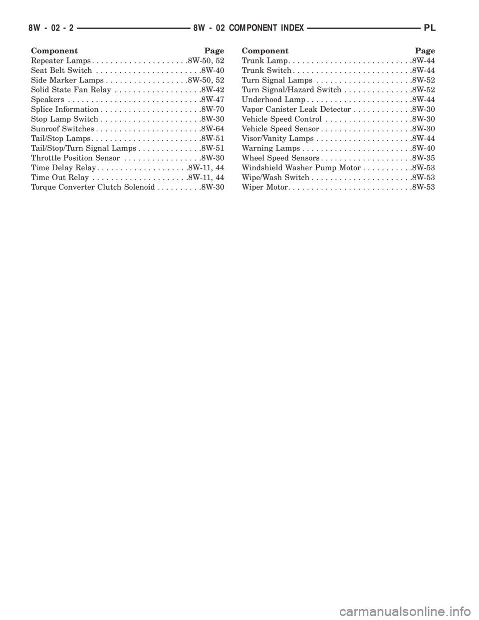
Component Page
Repeater Lamps.....................8W-50, 52
Seat Belt Switch.......................8W-40
Side Marker Lamps..................8W-50, 52
Solid State Fan Relay...................8W-42
Speakers.............................8W-47
Splice Information......................8W-70
Stop Lamp Switch......................8W-30
Sunroof Switches.......................8W-64
Tail/Stop Lamps........................8W-51
Tail/Stop/Turn Signal Lamps..............8W-51
Throttle Position Sensor.................8W-30
Time Delay Relay....................8W-11,44
Time Out Relay.....................8W-11,44
Torque Converter Clutch Solenoid..........8W-30Component Page
Trunk Lamp...........................8W-44
Trunk Switch..........................8W-44
Turn Signal Lamps.....................8W-52
Turn Signal/Hazard Switch...............8W-52
Underhood Lamp.......................8W-44
Vapor Canister Leak Detector.............8W-30
Vehicle Speed Control...................8W-30
Vehicle Speed Sensor....................8W-30
Visor/Vanity Lamps.....................8W-44
Warning Lamps........................8W-40
Wheel Speed Sensors....................8W-35
Windshield Washer Pump Motor...........8W-53
Wipe/Wash Switch......................8W-53
Wiper Motor...........................8W-53
8W - 02 - 2 8W - 02 COMPONENT INDEXPL
Page 412 of 1200
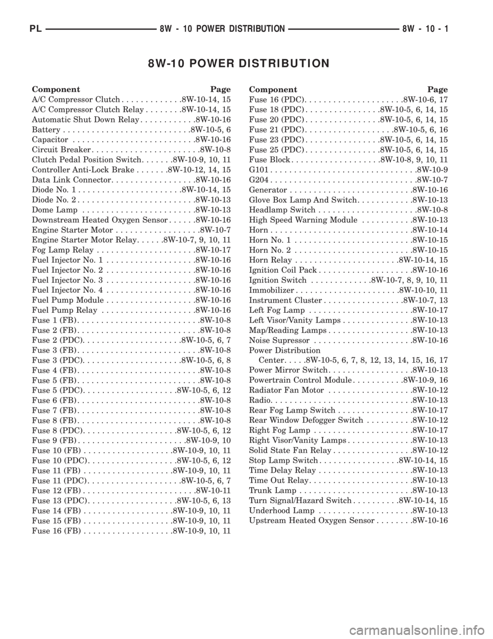
8W-10 POWER DISTRIBUTION
Component Page
A/C Compressor Clutch.............8W-10-14, 15
A/C Compressor Clutch Relay........8W-10-14, 15
Automatic Shut Down Relay............8W-10-16
Battery...........................8W-10-5, 6
Capacitor..........................8W-10-16
Circuit Breaker.......................8W-10-8
Clutch Pedal Position Switch.......8W-10-9, 10, 11
Controller Anti-Lock Brake.......8W-10-12, 14, 15
Data Link Connector..................8W-10-16
Diode No. 1......................8W-10-14, 15
Diode No. 2.........................8W-10-13
Dome Lamp........................8W-10-13
Downstream Heated Oxygen Sensor......8W-10-16
Engine Starter Motor..................8W-10-7
Engine Starter Motor Relay......8W-10-7, 9, 10, 11
Fog Lamp Relay.....................8W-10-17
Fuel Injector No. 1...................8W-10-16
Fuel Injector No. 2...................8W-10-16
Fuel Injector No. 3...................8W-10-16
Fuel Injector No. 4...................8W-10-16
Fuel Pump Module...................8W-10-16
Fuel Pump Relay....................8W-10-16
Fuse 1 (FB)..........................8W-10-8
Fuse 2 (FB)..........................8W-10-8
Fuse 2 (PDC).....................8W-10-5, 6, 7
Fuse 3 (FB)..........................8W-10-8
Fuse 3 (PDC).....................8W-10-5, 6, 8
Fuse 4 (FB)..........................8W-10-8
Fuse 5 (FB)..........................8W-10-8
Fuse 5 (PDC)....................8W-10-5, 6, 12
Fuse 6 (FB)..........................8W-10-8
Fuse 7 (FB)..........................8W-10-8
Fuse 8 (FB)..........................8W-10-8
Fuse 8 (PDC)....................8W-10-5, 6, 12
Fuse 9 (FB).......................8W-10-9, 10
Fuse 10 (FB)...................8W-10-9, 10, 11
Fuse 10 (PDC)...................8W-10-5, 6, 12
Fuse 11 (FB)...................8W-10-9, 10, 11
Fuse 11 (PDC)....................8W-10-5, 6, 7
Fuse 12 (FB)........................8W-10-11
Fuse 13 (PDC)...................8W-10-5, 6, 13
Fuse 14 (FB)...................8W-10-9, 10, 11
Fuse 15 (FB)...................8W-10-9, 10, 11
Fuse 16 (FB)...................8W-10-9, 10, 11Component Page
Fuse 16 (PDC).....................8W-10-6, 17
Fuse 18 (PDC)................8W-10-5, 6, 14, 15
Fuse 20 (PDC)................8W-10-5, 6, 14, 15
Fuse 21 (PDC)...................8W-10-5, 6, 16
Fuse 23 (PDC)................8W-10-5, 6, 14, 15
Fuse 25 (PDC)................8W-10-5, 6, 14, 15
Fuse Block...................8W-10-8, 9, 10, 11
G101...............................8W-10-9
G204...............................8W-10-7
Generator..........................8W-10-16
Glove Box Lamp And Switch............8W-10-13
Headlamp Switch.....................8W-10-8
High Speed Warning Module...........8W-10-13
Horn..............................8W-10-14
Horn No. 1.........................8W-10-15
Horn No. 2.........................8W-10-15
Horn Relay......................8W-10-14, 15
Ignition Coil Pack....................8W-10-16
Ignition Switch.............8W-10-7, 8, 9, 10, 11
Immobilizer......................8W-10-10, 11
Instrument Cluster.................8W-10-7, 13
Left Fog Lamp......................8W-10-17
Left Visor/Vanity Lamps...............8W-10-13
Map/Reading Lamps..................8W-10-13
Noise Supressor.....................8W-10-16
Power Distribution
Center.....8W-10-5, 6, 7, 8, 12, 13, 14, 15, 16, 17
Power Mirror Switch..................8W-10-13
Powertrain Control Module...........8W-10-9, 16
Radiator Fan Motor..................8W-10-12
Radio..............................8W-10-13
Rear Fog Lamp Switch................8W-10-17
Rear Window Defogger Switch..........8W-10-12
Right Fog Lamp.....................8W-10-17
Right Visor/Vanity Lamps..............8W-10-13
Solid State Fan Relay.................8W-10-12
Stop Lamp Switch.................8W-10-14, 15
Time Delay Relay....................8W-10-13
Time Out Relay......................8W-10-13
Trunk Lamp........................8W-10-13
Turn Signal/Hazard Switch..........8W-10-14, 15
Underhood Lamp....................8W-10-13
Upstream Heated Oxygen Sensor........8W-10-16
PL8W - 10 POWER DISTRIBUTION 8W - 10 - 1
Page 416 of 1200

BATTERY
1
22FUSE
40A
A2
12
PK/BK
40A
FUSE
3
3
4
A3
12
RD/WT
CENTER DISTRIBUTION
POWER7
88FUSE
30A 30A
FUSE
5
5
6
A16
14
GYA4
14
BK/RD
A0 8RD
12
1111FUSE
30A 20A
FUSE
18
18
1714
1313FUSE
10A 40A
FUSE
10
10
9
A20
12
RD/DGM1
18
PKA1
14
RD
19
2020FUSE
10A
L9
18
BK/WT
26
2525FUSE
15A 20A
FUSE
21
21
22
15A
FUSE
23
23
24
F32
18
PK/DB
IGNITION
SWITCH
TO TO
S213 SOLID
STATE
FAN
RELAY
TO
REAR
WINDOW
DEFOGGER
SWITCH
TO
TO
BRAKE ANTI-LOCK CONTROLLER
TO
S203A/C
COMPRESSOR
CLUTCH
RELAY
TO
IGNITION
SWITCH
TOTURN
SIGNAL/
HAZARD
SWITCH
TO
STOP
LAMP/
VEHICLE
SPEED
CONTROL
SWITCH
TOFUEL
PUMP/
ASD
RELAYS
(IN PDC)
TO
HORN
RELAY
(IN PDC)
TO
PK18 M1
UNDER
HOOD
LAMP
TO
(IN PDC)(IN PDC)
TO
RELAY MOTOR STARTERENGINE
S105
TO
RD/WT16 A14
(8W-20-2)
(8W-10-7) (8W-10-8) (8W-10-12)(8W-10-12)
(8W-10-7) (8W-10-14)(8W-10-13) (8W-10-12)(8W-10-14)
(8W-10-14) (8W-10-16) (8W-10-14)
PL8W-10 POWER DISTRIBUTION
EXCEPT BUILT-UP-EXPORT8W - 10 - 5
8194J988W-1