1999 DODGE NEON turn signal
[x] Cancel search: turn signalPage 338 of 1200
LAMP SERVICE
INDEX
page page
REMOVAL AND INSTALLATION
CENTER HIGH MOUNTED STOP LAMP
(CHMSL)............................. 10
DOME LAMP........................... 11
FOG LAMP.............................. 9
FRONT SIDE MARKER LAMP.............. 10
HEADLAMP MODULE..................... 9LICENSE PLATE LAMP................... 11
PARK AND TURN SIGNAL LAMP............. 9
REAR CARGO LAMP..................... 11
TAIL, STOP AND TURN SIGNAL LAMP........ 10
UNDERHOOD LAMP..................... 11
VISOR VANITY LAMP..................... 11
REMOVAL AND INSTALLATION
HEADLAMP MODULE
REMOVAL
(1) Release hood latch and open hood.
(2) From behind bumper fascia, remove bolt hold-
ing outboard end of module to fender and closure
panel.
(3) Loosen bolts holding inboard end of module to
radiator closure panel and remove bolt to grille.
(4) Remove bolts attaching top of module to upper
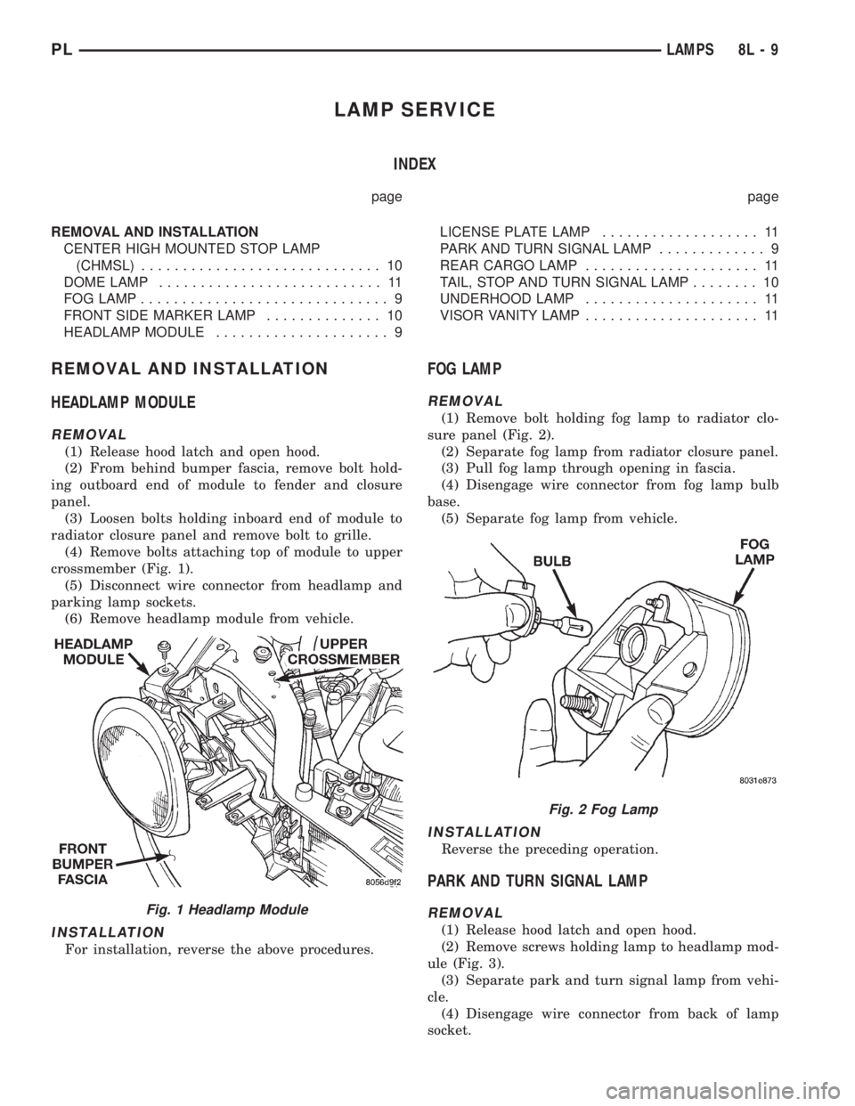
crossmember (Fig. 1).
(5) Disconnect wire connector from headlamp and
parking lamp sockets.
(6) Remove headlamp module from vehicle.
INSTALLATION
For installation, reverse the above procedures.
FOG LAMP
REMOVAL
(1) Remove bolt holding fog lamp to radiator clo-
sure panel (Fig. 2).
(2) Separate fog lamp from radiator closure panel.
(3) Pull fog lamp through opening in fascia.
(4) Disengage wire connector from fog lamp bulb
base.
(5) Separate fog lamp from vehicle.
INSTALLATION
Reverse the preceding operation.
PARK AND TURN SIGNAL LAMP
REMOVAL
(1) Release hood latch and open hood.
(2) Remove screws holding lamp to headlamp mod-
ule (Fig. 3).
(3) Separate park and turn signal lamp from vehi-
cle.
(4) Disengage wire connector from back of lamp
socket.
Fig. 1 Headlamp Module
Fig. 2 Fog Lamp
PLLAMPS 8L - 9
Page 339 of 1200
INSTALLATION
Reverse the preceding operation.
FRONT SIDE MARKER LAMP
REMOVAL
(1) Remove socket and bulb from side marker
lamp.
(2) Remove nuts holding side marker lamp to front
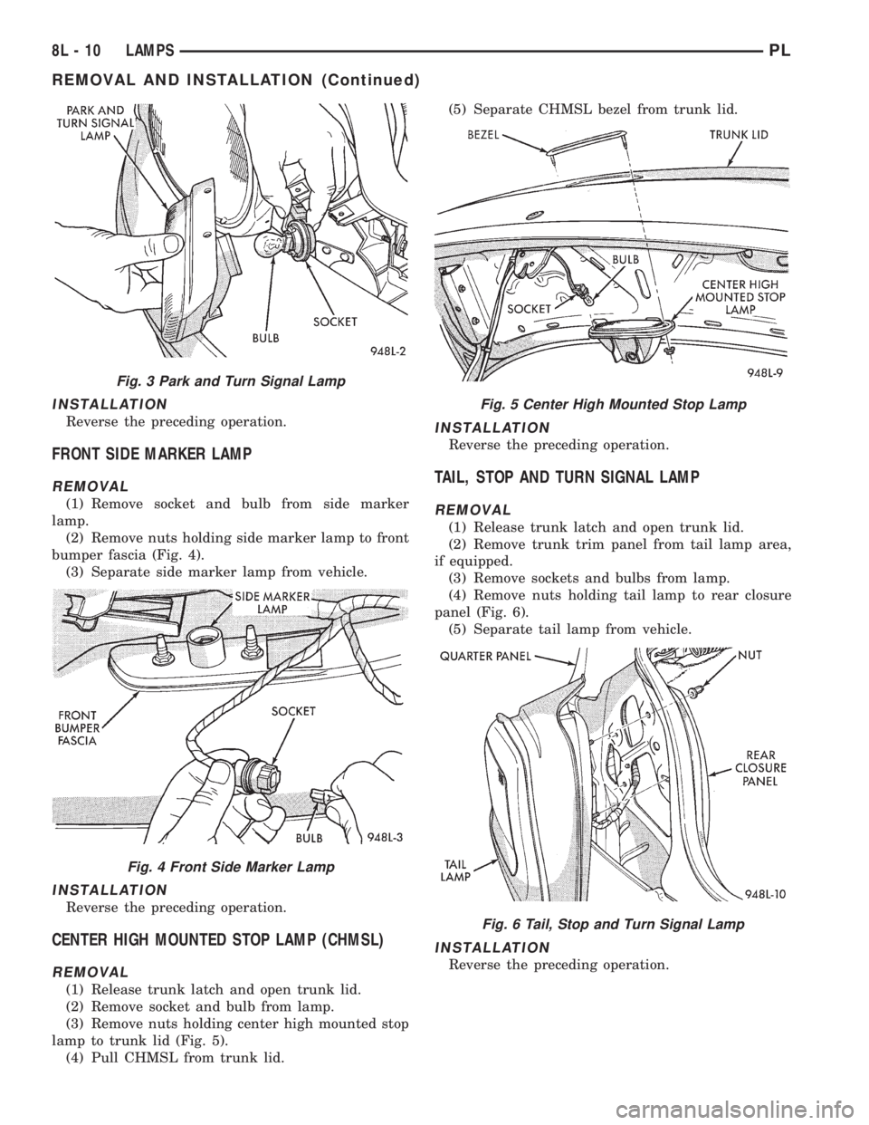
bumper fascia (Fig. 4).
(3) Separate side marker lamp from vehicle.
INSTALLATION
Reverse the preceding operation.
CENTER HIGH MOUNTED STOP LAMP (CHMSL)
REMOVAL
(1) Release trunk latch and open trunk lid.
(2) Remove socket and bulb from lamp.
(3) Remove nuts holding center high mounted stop
lamp to trunk lid (Fig. 5).
(4) Pull CHMSL from trunk lid.(5) Separate CHMSL bezel from trunk lid.
INSTALLATION
Reverse the preceding operation.
TAIL, STOP AND TURN SIGNAL LAMP
REMOVAL
(1) Release trunk latch and open trunk lid.
(2) Remove trunk trim panel from tail lamp area,
if equipped.
(3) Remove sockets and bulbs from lamp.
(4) Remove nuts holding tail lamp to rear closure
panel (Fig. 6).
(5) Separate tail lamp from vehicle.
INSTALLATION
Reverse the preceding operation.
Fig. 3 Park and Turn Signal Lamp
Fig. 4 Front Side Marker Lamp
Fig. 5 Center High Mounted Stop Lamp
Fig. 6 Tail, Stop and Turn Signal Lamp
8L - 10 LAMPSPL
REMOVAL AND INSTALLATION (Continued)
Page 342 of 1200
BULB APPLICATION
INDEX
page page
SPECIFICATIONS
EXTERIOR LAMPS....................... 13GENERAL INFORMATION................. 13
INTERIOR LAMPS....................... 13
SPECIFICATIONS
GENERAL INFORMATION
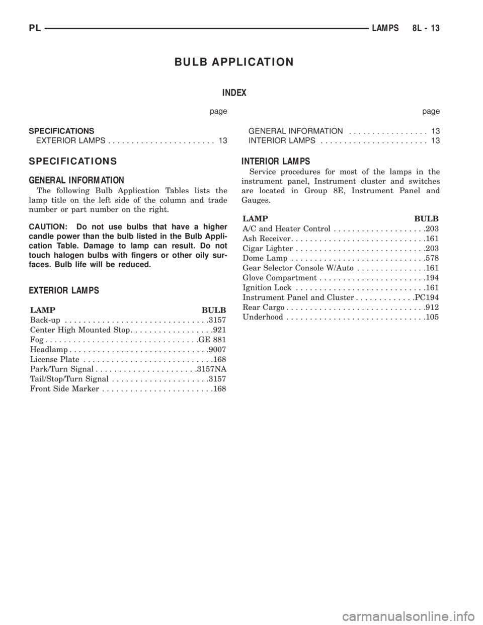
The following Bulb Application Tables lists the
lamp title on the left side of the column and trade
number or part number on the right.
CAUTION: Do not use bulbs that have a higher
candle power than the bulb listed in the Bulb Appli-
cation Table. Damage to lamp can result. Do not
touch halogen bulbs with fingers or other oily sur-
faces. Bulb life will be reduced.
EXTERIOR LAMPS
LAMP BULB
Back-up...............................3157
Center High Mounted Stop..................921
Fog.................................GE881
Headlamp..............................9007
License Plate............................168
Park/Turn Signal......................3157NA
Tail/Stop/Turn Signal.....................3157
Front Side Marker........................168
INTERIOR LAMPS
Service procedures for most of the lamps in the
instrument panel, Instrument cluster and switches
are located in Group 8E, Instrument Panel and
Gauges.
LAMP BULB
A/C and Heater Control....................203
Ash Receiver.............................161
Cigar Lighter............................203
Dome Lamp.............................578
Gear Selector Console W/Auto...............161
Glove Compartment.......................194
Ignition Lock............................161
Instrument Panel and Cluster.............PC194
Rear Cargo..............................912
Underhood..............................105
PLLAMPS 8L - 13
Page 345 of 1200
LAMP BULB SERVICE
INDEX
page page
REMOVAL AND INSTALLATION
CITYLIGHT LAMP BULB.................... 3
FOG LAMP BULB......................... 3FRONT TURN SIGNAL LAMP BULB........... 2
HEADLAMP BULB........................ 2
SIDE REPEATER LAMP BULB............... 4
REMOVAL AND INSTALLATION
HEADLAMP BULB
REMOVAL
(1) Release hood latch and open hood.
(2) Disengage wire connector to headlamp bulb.
(3) Remove headlamp assembly from vehicle.
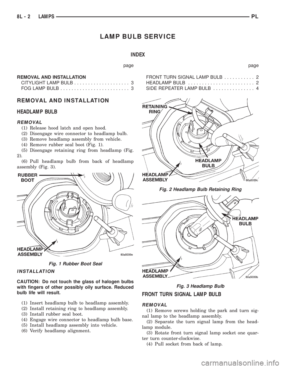
(4) Remove rubber seal boot (Fig. 1).
(5) Disengage retaining ring from headlamp (Fig.
2).
(6) Pull headlamp bulb from back of headlamp
assembly (Fig. 3).
INSTALLATION
CAUTION: Do not touch the glass of halogen bulbs
with fingers of other possibly oily surface. Reduced
bulb life will result.
(1) Insert headlamp bulb to headlamp assembly.
(2) Install retaining ring to headlamp assembly.
(3) Install rubber seal boot.
(4) Engage wire connector to headlamp bulb base.
(5) Install headlamp assembly into vehicle.
(6) Verify headlamp alignment.
FRONT TURN SIGNAL LAMP BULB
REMOVAL
(1) Remove screws holding the park and turn sig-
nal lamp to the headlamp assembly.
(2) Separate the turn signal lamp from the head-
lamp module.
(3) Rotate front turn signal lamp socket one quar-
ter turn counter-clockwise.
(4) Pull socket from back of lamp.
Fig. 1 Rubber Boot Seal
Fig. 2 Headlamp Bulb Retaining Ring
Fig. 3 Headlamp Bulb
8L - 2 LAMPSPL
Page 346 of 1200
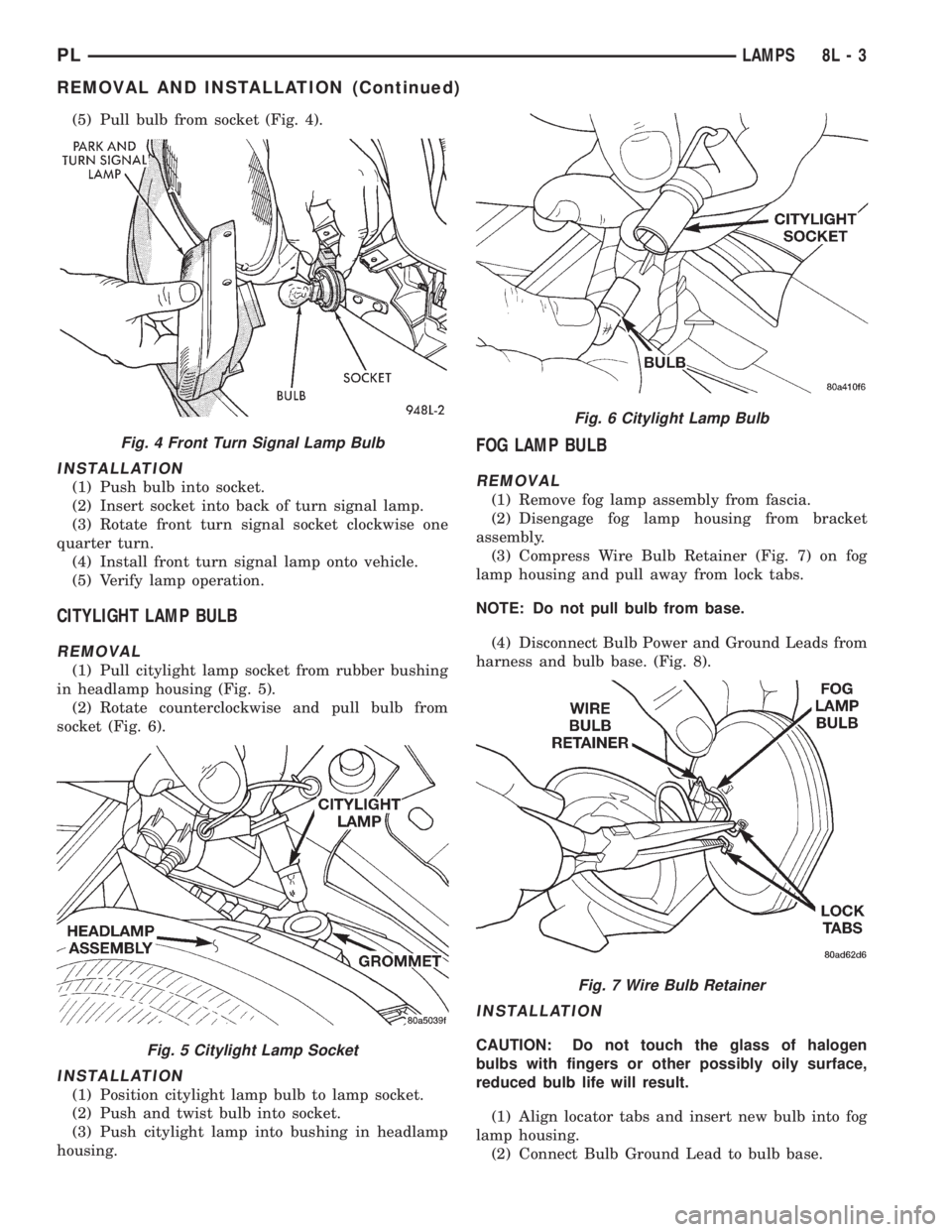
(5) Pull bulb from socket (Fig. 4).
INSTALLATION
(1) Push bulb into socket.
(2) Insert socket into back of turn signal lamp.
(3) Rotate front turn signal socket clockwise one
quarter turn.
(4) Install front turn signal lamp onto vehicle.
(5) Verify lamp operation.
CITYLIGHT LAMP BULB
REMOVAL
(1) Pull citylight lamp socket from rubber bushing
in headlamp housing (Fig. 5).
(2) Rotate counterclockwise and pull bulb from
socket (Fig. 6).
INSTALLATION
(1) Position citylight lamp bulb to lamp socket.
(2) Push and twist bulb into socket.
(3) Push citylight lamp into bushing in headlamp
housing.
FOG LAMP BULB
REMOVAL
(1) Remove fog lamp assembly from fascia.
(2) Disengage fog lamp housing from bracket
assembly.
(3) Compress Wire Bulb Retainer (Fig. 7) on fog
lamp housing and pull away from lock tabs.
NOTE: Do not pull bulb from base.
(4) Disconnect Bulb Power and Ground Leads from
harness and bulb base. (Fig. 8).
INSTALLATION
CAUTION: Do not touch the glass of halogen
bulbs with fingers or other possibly oily surface,
reduced bulb life will result.
(1) Align locator tabs and insert new bulb into fog
lamp housing.
(2) Connect Bulb Ground Lead to bulb base.
Fig. 4 Front Turn Signal Lamp Bulb
Fig. 5 Citylight Lamp Socket
Fig. 6 Citylight Lamp Bulb
Fig. 7 Wire Bulb Retainer
PLLAMPS 8L - 3
REMOVAL AND INSTALLATION (Continued)
Page 348 of 1200
LAMP SERVICE
INDEX
page page
GENERAL INFORMATION
HEADLAMP DIMMER SWITCH............... 5
HEADLAMP SWITCH...................... 5
REMOVAL AND INSTALLATION
FOG LAMP.............................. 6HEADLAMP ASSEMBLY.................... 5
HEADLAMP LEVELING MOTOR.............. 6
SIDE REPEATER LAMP.................... 6
GENERAL INFORMATION
HEADLAMP SWITCH
Service procedures for the headlamp switch can be
found in Group 8E, Instrument Panel and Gauges.
More information can be found in Group 8W, Wiring
Diagrams.
HEADLAMP DIMMER SWITCH
The headlamp dimmer switch is incorporated into
the multi-function (turn signal) switch. Proper proce-
dures can be found in Group 8J, Turn Signal and
Flashers. More information can be found in Group
8W, Wiring Diagrams.
REMOVAL AND INSTALLATION
HEADLAMP ASSEMBLY
REMOVAL
(1) Release hood latch and open hood.
(2) Remove headlamp horizontal aim cable from
retainer clip on radiator upper crossmember.
(3) Disengage wire connector from leveling motor.
(4) Remove bolts holding headlamp leveling motor
to the upper radiator crossmember.
(5) Remove plastic locking cap holding vertical lev-
eling cable into leveling motor arm.
(6) Separate leveling cable from motor arm.
(7) Rotate leveling cable case one quarter turn
counter-clockwise and separate cable from motor
bracket.
(8) Separate leveling motor and bracket from vehi-
cle.
(9) From between front fascia and headlamp
assembly, remove bolt holding outboard end of
assembly to fender.
(10) Remove bolts holding inboard end of assembly
to radiator closure panel.
(11) Remove bolts holding top of assembly to upper
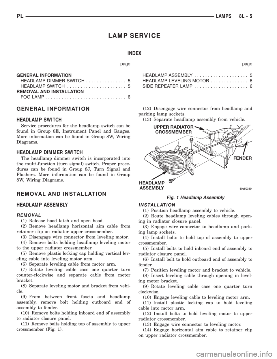
crossmember (Fig. 1).(12) Disengage wire connector from headlamp and
parking lamp sockets.
(13) Separate headlamp assembly from vehicle.
INSTALLATION
(1) Position headlamp assembly to vehicle.
(2) Route headlamp leveling cables through open-
ing in radiator closure panel.
(3) Engage wire connector to headlamp and park-
ing lamp sockets.
(4) Install bolts to hold top of assembly to upper
crossmember.
(5) Install bolts to hold inboard end of assembly to
radiator closure panel.
(6) Install bolt to hold outboard end of assembly to
fender.
(7) Position leveling motor and bracket to vehicle.
(8) Insert leveling cable through opening in level-
ing motor bracket.
(9) Rotate leveling cable case one quarter turn
clockwise.
(10) Engage leveling cable to leveling motor arm.
(11) Install plastic locking cap to hold leveling
cable into motor arm.
(12) Install bolts to hold leveling motor to upper
radiator crossmember.
(13) Engage wire connector to leveling motor.
(14) Engage horizontal aim cable to retainer clip
on upper radiator crossmember.
Fig. 1 Headlamp Assembly
PLLAMPS 8L - 5
Page 351 of 1200
BULB APPLICATION
INDEX
page page
GENERAL INFORMATION
INTRODUCTION......................... 8
SPECIFICATIONS
EXTERIOR LAMPS........................ 8INTERIOR LAMPS........................ 8
GENERAL INFORMATION
INTRODUCTION
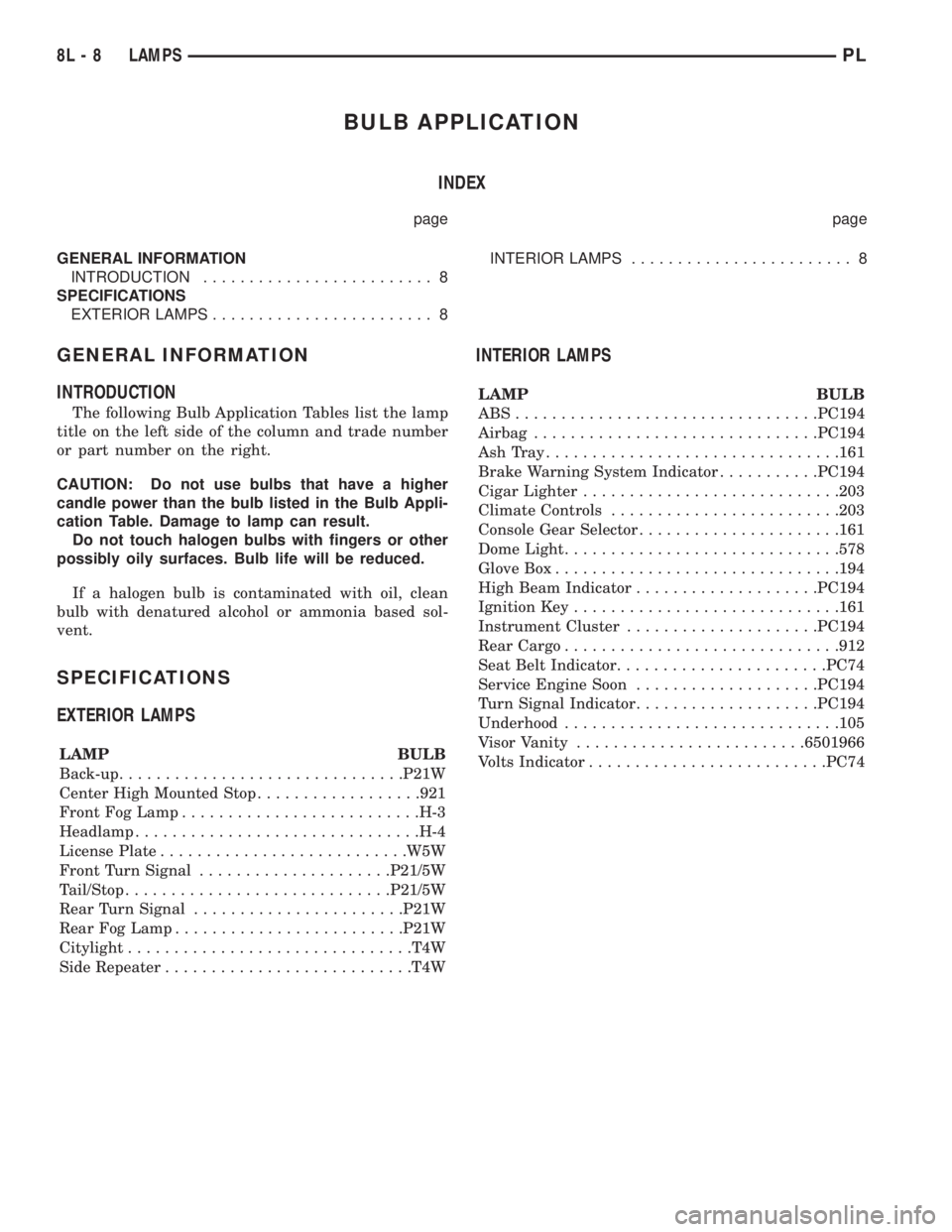
The following Bulb Application Tables list the lamp
title on the left side of the column and trade number
or part number on the right.
CAUTION: Do not use bulbs that have a higher
candle power than the bulb listed in the Bulb Appli-
cation Table. Damage to lamp can result.
Do not touch halogen bulbs with fingers or other
possibly oily surfaces. Bulb life will be reduced.
If a halogen bulb is contaminated with oil, clean
bulb with denatured alcohol or ammonia based sol-
vent.
SPECIFICATIONS
EXTERIOR LAMPS
LAMP BULB
Back-up...............................P21W
Center High Mounted Stop..................921
Front Fog Lamp..........................H-3
Headlamp...............................H-4
License Plate...........................W5W
Front Turn Signal.....................P21/5W
Tail/Stop.............................P21/5W
Rear Turn Signal.......................P21W
Rear Fog Lamp.........................P21W
Citylight...............................T4W
Side Repeater...........................T4W
INTERIOR LAMPS
LAMP BULB
ABS.................................PC194
Airbag...............................PC194
AshTray................................161
Brake Warning System Indicator...........PC194
Cigar Lighter............................203
Climate Controls.........................203
Console Gear Selector......................161
Dome Light..............................578
Glove Box...............................194
High Beam Indicator....................PC194
Ignition Key.............................161
Instrument Cluster.....................PC194
Rear Cargo..............................912
Seat Belt Indicator.......................PC74
Service Engine Soon....................PC194
Turn Signal Indicator....................PC194
Underhood..............................105
Visor Vanity.........................6501966
Volts Indicator..........................PC74
8L - 8 LAMPSPL
Page 359 of 1200
CLOCKSPRING
REMOVAL
WARNING: DISCONNECT AND ISOLATE THE BAT-
TERY NEGATIVE (GROUND) CABLE BEFORE
BEGINNING ANY AIRBAG SYSTEM COMPONENT
REMOVAL OR INSTALLATION PROCEDURE. THIS
WILL DISABLE THE AIRBAG SYSTEM. FAILURE TO
DISCONNECT BATTERY COULD RESULT IN ACCI-
DENTAL AIRBAG DEPLOYMENT AND POSSIBLE
PERSONAL INJURY. ALLOW SYSTEM CAPACITOR
TO DISCHARGE FOR 2 MINUTES BEFORE REMOV-
ING ANY AIRBAG COMPONENTS.
(1) Place the front road wheels in the straight
ahead position then:
²Rotate the steering wheel half turn (180
degrees) to the right (clockwise)
²Lock column with ignition lock cylinder.
(2) Disconnect and isolate the battery negative
cable.
(3) Wait two minutes for the reserve capacitor to
discharge before removing non-deployed module.
(4) Remove speed control switch mounting screws,
switches and disconnect the wire connectors or
remove covers.
(5) Remove the Driver Airbag Module attaching
bolts from under the speed control switches or covers.
(6) Lift module and disconnect the airbag and horn
wire connectors.
(7) Remove the steering wheel, refer to Steering
Wheel removal procedures.
(8) Remove upper and lower steering column
shrouds to gain access to clockspring wiring.
(9) Disconnect the 2-way and 4-way connectors
between the clockspring and the instrument panel
wiring harness at the base of the clockspring (Fig.
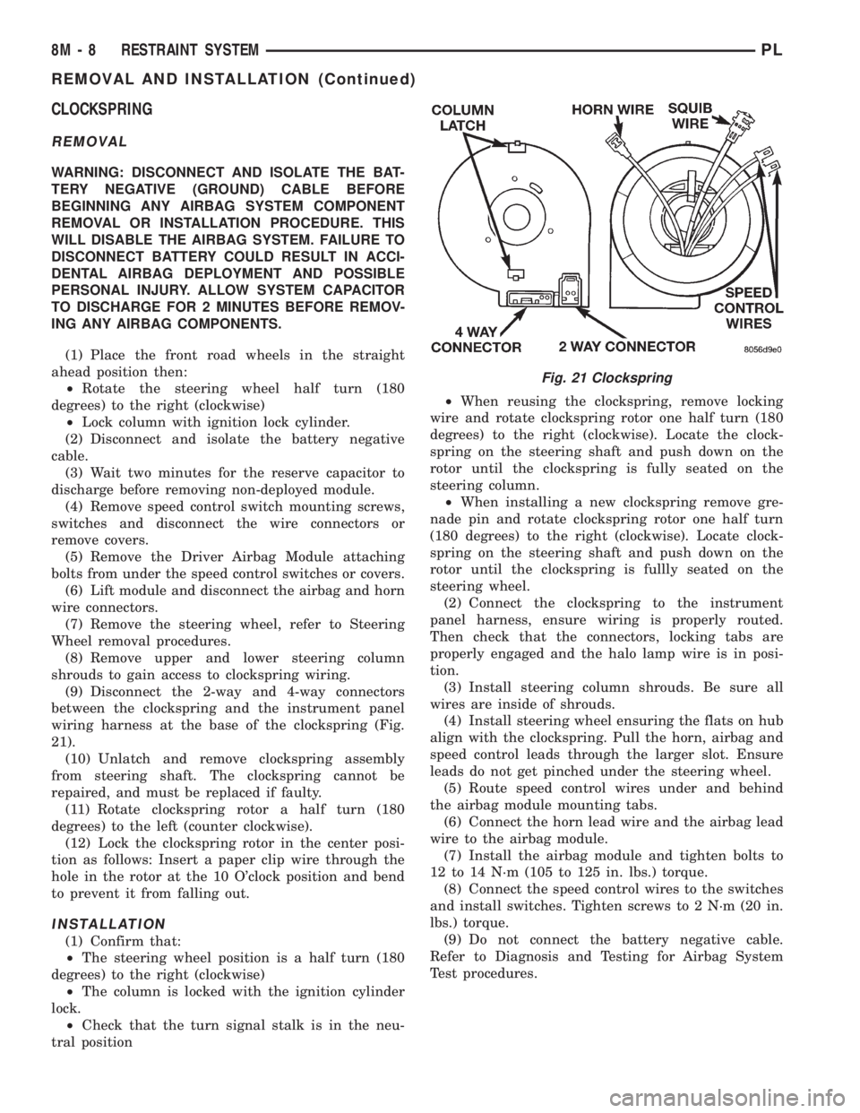
21).
(10) Unlatch and remove clockspring assembly
from steering shaft. The clockspring cannot be
repaired, and must be replaced if faulty.
(11) Rotate clockspring rotor a half turn (180
degrees) to the left (counter clockwise).
(12) Lock the clockspring rotor in the center posi-
tion as follows: Insert a paper clip wire through the
hole in the rotor at the 10 O'clock position and bend
to prevent it from falling out.
INSTALLATION
(1) Confirm that:
²The steering wheel position is a half turn (180
degrees) to the right (clockwise)
²The column is locked with the ignition cylinder
lock.
²Check that the turn signal stalk is in the neu-
tral position²When reusing the clockspring, remove locking
wire and rotate clockspring rotor one half turn (180
degrees) to the right (clockwise). Locate the clock-
spring on the steering shaft and push down on the
rotor until the clockspring is fully seated on the
steering column.
²When installing a new clockspring remove gre-
nade pin and rotate clockspring rotor one half turn
(180 degrees) to the right (clockwise). Locate clock-
spring on the steering shaft and push down on the
rotor until the clockspring is fullly seated on the
steering wheel.
(2) Connect the clockspring to the instrument
panel harness, ensure wiring is properly routed.
Then check that the connectors, locking tabs are
properly engaged and the halo lamp wire is in posi-
tion.
(3) Install steering column shrouds. Be sure all
wires are inside of shrouds.
(4) Install steering wheel ensuring the flats on hub
align with the clockspring. Pull the horn, airbag and
speed control leads through the larger slot. Ensure
leads do not get pinched under the steering wheel.
(5) Route speed control wires under and behind
the airbag module mounting tabs.
(6) Connect the horn lead wire and the airbag lead
wire to the airbag module.
(7) Install the airbag module and tighten bolts to
12 to 14 N´m (105 to 125 in. lbs.) torque.
(8) Connect the speed control wires to the switches
and install switches. Tighten screws to 2 N´m (20 in.
lbs.) torque.
(9) Do not connect the battery negative cable.
Refer to Diagnosis and Testing for Airbag System
Test procedures.
Fig. 21 Clockspring
8M - 8 RESTRAINT SYSTEMPL
REMOVAL AND INSTALLATION (Continued)