1999 DODGE NEON turn signal
[x] Cancel search: turn signalPage 275 of 1200

(8) If all tests performed test good, replace the dial
and gauge assembly.
(9) If the tachometer continues to be inoperative,
replace the print circuit board.
TEMPERATURE GAUGE
(1) Disconnect the coolant temperature sensor
(Fig. 12).
(2) Turn ignition switch ON. The temperature
gauge should be at its lowest position. Turn ignition
switch OFF.
(3) Ground temperature gauge sending unit con-
nector Pin 3. Refer to Group 8W, wiring Diagrams.
Turn ignition switch ON. The temperature gauge
should be at its highest position. After the seat belt
lamp goes out, the cluster should chime for about
eight seconds.
(a) If OK, check temperature sending unit con-
nector for proper connection. If connections are OK,
replace the sending unit.
(b) If not OK, and the high temperature chime
sounds but the gauge shows cold, replace the gauge
assembly. If gauge is still not working, replace the
printed circuit board.
SPEEDOMETER SYSTEM
The vehicle is equipped with a electronically driven
speedometer and odometer assemblies. A signal is
sent from a transmission-mounted vehicle speed sen-
sor to the speedometer circuitry through the wiring
harness.
SEAT BELT REMINDER SYSTEM TEST
For testing of this system refer to Group 8U,
Chime Warning/Reminder Systems.
SENDING UNIT
When a problem occurs with a cluster gauge check
for a defective sending unit or wiring. Do this before
disassembling the cluster.(1) Sending units and wiring can be checked by
grounding the connector leads at the sending unit in
the vehicle.
(2) With the ignition in the ON position, a
grounded input will cause the fuel or temperature
gauge to read at or above maximum.
SERVICE ENGINE SOON INDICATOR
Refer to Group 25, Emission Control Systems for
procedures.
VEHICLE SPEED SENSOR TEST
To test the vehicle speed sensor and related compo-
nents use a scan tool (DRB), and refer to the appro-
priate Powertrain Diagnostics Test Procedure
Manual.
REMOVAL AND INSTALLATION
ASH RECEIVER RETAINER AND LAMP
REMOVAL
(1) Open up and remove the ash receiver recepta-
cle.
(2) Remove the center bezel.
(3) Remove the two ash receiver retainer attaching
screws from the upper-rearward face and remove
retainer.
(4) For lamp replacement, remove the clamp and
lamp hood from the top of the retainer. Remove the
wiring clip at the forward edge of the retainer and
remove the lamp socket from the hood and replace
lamp.
INSTALLATION
For installation reverse the above procedures.
When installing the retainer ensure that the forward
tabs are inserted properly into the slots in the instru-
ment panel.
CENTER BEZEL
REMOVAL
(1) Open the ash receiver receptacle.
(2) Grasp the bezel and pull rearward disengaging
the clips.
INSTALLATION
For installation, reverse the above procedures.
CIGAR LIGHTER RECEPTACLE
REMOVAL
(1) Remove the cigar lighter element.
(2) Reach underneath the instrument panel
through the bottom access hole and disconnect the
cigar lighter receptacle wiring connectors.
Fig. 12 Engine Coolant Temperature Sensor
8E - 6 INSTRUMENT PANEL AND SYSTEMSPL
DIAGNOSIS AND TESTING (Continued)
Page 299 of 1200
SPEED CONTROL SWITCHES
There are two separate switch pods that operate
the speed control system. The steering-wheel-
mounted switches use multiplexed circuits to provide
inputs to the PCM for ON, OFF, RESUME, ACCEL-
ERATE, SET, DECEL and CANCEL modes. Refer to
the owner's manual for more information on speed
control switch functions and setting procedures.When speed control is selected by depressing the
ON switch, the PCM allows a set speed to be stored
in RAM for speed control. To store a set speed,
depress the SET switch while the vehicle is moving
at a speed between 30 and 85 mph. In order for the
speed control to engage, the brakes cannot be
applied, nor can the gear selector be indicating the
transmission is in Park or Neutral.
The speed control can be disengaged manually by:
²Stepping on the brake pedal
²Depressing the OFF switch
²Depressing the CANCEL switch.
NOTE: Depressing the OFF switch or turning off
the ignition switch will erase the set speed stored
in the PCM.
For added safety,the speed control system is pro-
grammed to disengaged for any of the following con-
ditions:
²An indication of Park or Neutral
²An rpm increase without a VSS signal increase
(indicates that the clutch has been disengaged)
²Excessive engine rpm (indicates that the trans-
mission may be in a low gear)
²The VSS signal increases at a rate of 10 mph
per second (indicates that the co-efficient of friction
between the road surface and tires is extremely low)
²The VSS signal decreases at a rate of 10 mph
per second (indicates that the vehicle may have
decelerated at an extremely high rate)
²If the actual speed is not within 20 mph of the
set speed
The previous disengagement conditions are pro-
grammed for added safety.
Once the speed control has been disengaged,
depressing the ACCEL switch when speed is greater
than 25 mph restores the vehicle to the target speed
that was stored in the PCM.
NOTE: Depressing the OFF switch will erase the
set speed stored in the PCM's RAM.
While the speed control is engaged, the driver can
increase the vehicle speed by depressing the ACCEL
switch. The new target speed is stored in the PCM
when the ACCEL is released. The PCM also has a
9tap-up9feature in which vehicle speed increases at a
rate of approximately 2 mph for each momentary
switch activation of the ACCEL switch. The PCM
also provides a means to decelerate without disen-
gaging speed control. To decelerate from an existing
recorded target speed, depress and hold the COAST
switch until the desired speed is reached, then
release the switch.
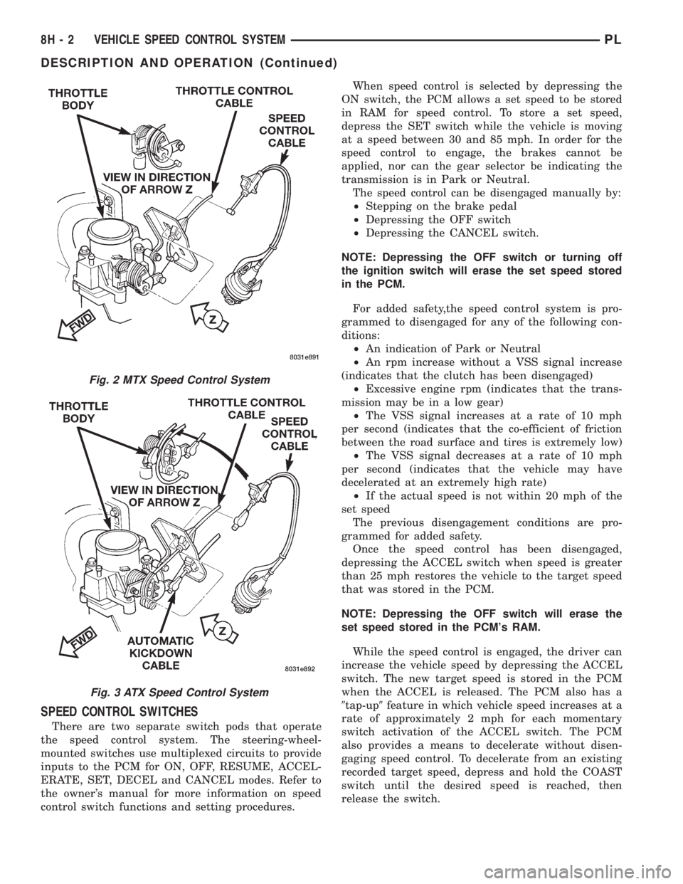
Fig. 2 MTX Speed Control System
Fig. 3 ATX Speed Control System
8H - 2 VEHICLE SPEED CONTROL SYSTEMPL
DESCRIPTION AND OPERATION (Continued)
Page 310 of 1200
TURN SIGNAL AND FLASHERS
CONTENTS
page page
GENERAL INFORMATION
INTRODUCTION......................... 1
DESCRIPTION AND OPERATION
COMBINATION FLASHER.................. 1
HAZARD WARNING SYSTEM............... 1DIAGNOSIS AND TESTING
MULTI-FUNCTION SWITCH................ 2
MULTI-FUNCTION SWITCH TEST............ 2
REMOVAL AND INSTALLATION
MULTI-FUNCTION SWITCH................ 4
GENERAL INFORMATION
INTRODUCTION
WARNING: ON VEHICLES EQUIPPED WITH AIR-
BAG, SEE GROUP 8M, RESTRAINT SYSTEMS FOR
AIRBAG REMOVAL PROCEDURES.
The turn signals are part of the multi-function
switch. Which contains:
²Electrical circuitry for turn signals
²Hazard warning switch
²Headlamp beam select switch
²Headlamp optical horn
The integrated switch assembly is mounted to the
left hand side of the steering column. When the
driver wishes to signal his intentions to change direc-
tion of travel, he moves the lever upward to cause
the right signals to flash and downward to cause the
left signals to flash. After completion of a turn the
system is deactivated automatically. As the steering
wheel returns to the straight ahead position, a can-
celing cam molded to the clockspring mechanism
comes in contact with the cancel actuator on the turn
signal multi-function switch assembly. The cam lobe,
pushing on the cancel actuator, returns the switch to
the off position.
If only momentary signaling such as indication of a
lane change is desired, the switch is actuated to a
left or right intermediate detent position. In this
position the signal lamps flash as described above,
but the switch returns to the OFF position as soon as
the lever is released.
When the system is activated, one of two indicator
lamps mounted in the instrument cluster flashes in
unison with the turn signal lamps, indicating to the
driver that the system is operating.
DESCRIPTION AND OPERATION
HAZARD WARNING SYSTEM
The hazard warning system is actuated by a slide
button located on the top of the steering column
between the steering wheel and the instrument
panel. The hazard switch is identified with a double
triangle on front of the button.
COMBINATION FLASHER
The turn signal flasher and the hazard warning
flasher are combined into one unit called a combina-
tion flasher (combo-flasher). The combo- flasher con-
trols the flashing of the hazard warning system and
the turn signal system. An inoperative bulb or incom-
plete turn signal circuit will cause the flasher rate to
double.
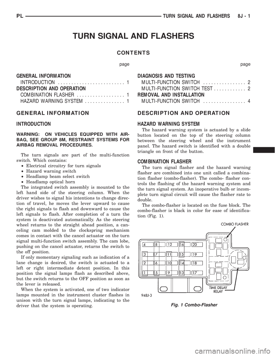
The combo-flasher is located on the fuse block. The
combo-flasher is black in color for ease of identifica-
tion (Fig. 1).
Fig. 1 Combo-Flasher
PLTURN SIGNAL AND FLASHERS 8J - 1
Page 311 of 1200
DIAGNOSIS AND TESTING
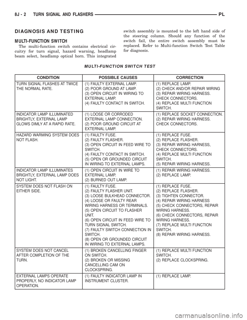
MULTI-FUNCTION SWITCH
The multi-function switch contains electrical cir-
cuitry for turn signal, hazard warning, headlamp
beam select, headlamp optical horn. This integratedswitch assembly is mounted to the left hand side of
the steering column. Should any function of the
switch fail, the entire switch assembly must be
replaced. Refer to Multi-function Switch Test Table
for diagnosis.
MULTI-FUNCTION SWITCH TEST
CONDITION POSSIBLE CAUSES CORRECTION
TURN SIGNAL FLASHES AT TWICE
THE NORMAL RATE.(1) FAULTY EXTERNAL LAMP.
(2) POOR GROUND AT LAMP.
(3) OPEN CIRCUIT IN WIRING TO
EXTERNAL LAMP.
(4) FAULTY CONTACT IN SWITCH.(1) REPLACE LAMP.
(2) CHECK AND/OR REPAIR WIRING
(3) REPAIR WIRING HARNESS.
CHECK CONNECTORS.
(4) REPLACE MULTI FUNCTION
SWITCH.
INDICATOR LAMP ILLUMINATED
BRIGHTLY, EXTERNAL LAMP
GLOWS DIMLY AT A RAPID RATE.(1) LOOSE OR CORRODED
EXTERNAL LAMP CONNECTION.
(2) POOR GROUND CIRCUIT AT
EXTERNAL LAMP.(1) REPLACE SOCKET CONNECTION.
(2) REPAIR WIRING HARNESS.
CHECK CONNECTORS.
HAZARD WARMING SYSTEM DOES
NOT FLASH.(1) FAULTY FUSE.
(2) FAULTY FLASHER.
(3) OPEN CIRCUIT IN FEED WIRE TO
SWITCH.
(4) FAULTY CONTACT IN SWITCH.
(5) OPEN OR GROUNDED CIRCUIT
IN WIRING TO EXTERNAL LAMPS.(1) REPLACE FUSE.
(2) REPLACE FLASHER.
(3) REPAIR WIRING HARNESS,
CHECK CONNECTORS.
(4) REPLACE MULTI FUNCTION
SWITCH.
(5) REPAIR WIRING HARNESS.
INDICATOR LAMP ILLUMINATES
BRIGHTLY, EXTERNAL LAMP DOES
NOT LIGHT.(1) OPEN CIRCUIT IN WIRE TO
EXTERNAL LAMP.
(2) BURNED OUT LAMP.(1) REPAIR WIRING HARNESS.
(2) REPLACE LAMP.
SYSTEM DOES NOT FLASH ON
EITHER SIDE.(1) FAULTY FUSE.
(2) FAULTY FLASHER UNIT.
(3) LOOSE BULKHEAD CONNECTOR.
(4) LOOSE OR FAULTY REAR
WIRING HARNESS OR TERMINALS.
(5) OPEN CIRCUIT TO FLASHER
UNIT.
(6) OPEN CIRCUIT IN FEED WIRE TO
TURN SIGNAL SWITCH.
(7) FAULTY SWITCH CONNECTION IN
SWITCH.
(8) OPEN OR GROUNDED CIRCUIT
IN WIRING TO EXTERNAL LAMPS.(1) REPLACE FUSE.
(2) REPLACE FLASHER.
(3) TIGHTEN CONNECTOR.
(4) REPAIR WIRING HARNESS
(5) CHECK CONNECTORS, REPAIR
WIRING HARNESS.
(6) CHECK CONNECTORS, REPAIR
WIRING HARNESS.
(7) REPLACE MULTI FUNCTION
SWITCH.
(8) REPAIR WIRING HARNESS.
SYSTEM DOES NOT CANCEL
AFTER COMPLETION OF THE
TURN.(1) BROKEN CANCELLING FINGER
ON SWITCH.
(2) BROKEN OR MISSING
CANCELLING CAM ON
CLOCKSPRING.(1) REPLACE MULTI FUNCTION
SWITCH.
(2) REPLACE CLOCKSPRING.
EXTERNAL LAMPS OPERATE
PROPERLY, NO INDICATOR LAMP
OPERATION.(1) FAULTY INDICATOR LAMP IN
INSTRUMENT CLUSTER.(1) REPLACE LAMP.
8J - 2 TURN SIGNAL AND FLASHERSPL
Page 312 of 1200
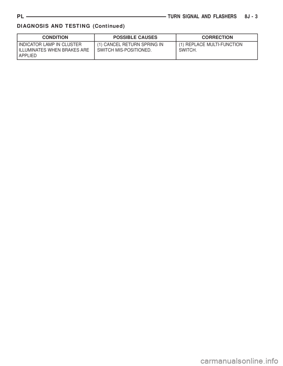
CONDITION POSSIBLE CAUSES CORRECTION
INDICATOR LAMP IN CLUSTER
ILLUMINATES WHEN BRAKES ARE
APPLIED(1) CANCEL RETURN SPRING IN
SWITCH MIS-POSITIONED.(1) REPLACE MULTI-FUNCTION
SWITCH.
PLTURN SIGNAL AND FLASHERS 8J - 3
DIAGNOSIS AND TESTING (Continued)
Page 313 of 1200
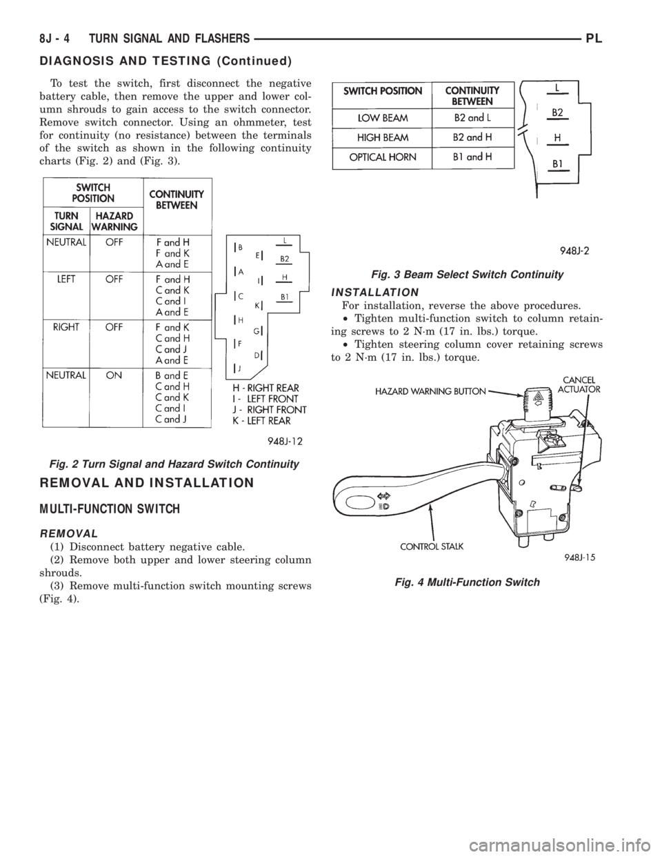
To test the switch, first disconnect the negative
battery cable, then remove the upper and lower col-
umn shrouds to gain access to the switch connector.
Remove switch connector. Using an ohmmeter, test
for continuity (no resistance) between the terminals
of the switch as shown in the following continuity
charts (Fig. 2) and (Fig. 3).
REMOVAL AND INSTALLATION
MULTI-FUNCTION SWITCH
REMOVAL
(1) Disconnect battery negative cable.
(2) Remove both upper and lower steering column
shrouds.
(3) Remove multi-function switch mounting screws
(Fig. 4).
INSTALLATION
For installation, reverse the above procedures.
²Tighten multi-function switch to column retain-
ing screws to 2 N´m (17 in. lbs.) torque.
²Tighten steering column cover retaining screws
to 2 N´m (17 in. lbs.) torque.
Fig. 2 Turn Signal and Hazard Switch Continuity
Fig. 3 Beam Select Switch Continuity
Fig. 4 Multi-Function Switch
8J - 4 TURN SIGNAL AND FLASHERSPL
DIAGNOSIS AND TESTING (Continued)
Page 335 of 1200
LAMP BULB SERVICE
INDEX
page page
REMOVAL AND INSTALLATION
CENTER HIGH MOUNTED STOP LAMP BULB . . . 7
DOME LAMP BULB....................... 8
FOG LAMP BULB......................... 6
FRONT SIDE MARKER LAMP BULB.......... 7
HEADLAMP BULB........................ 6
LICENSE PLATE LAMP BULB............... 8PARK AND TURN SIGNAL LAMP BULB........ 6
REAR CARGO LAMP BULB................. 8
TAIL, STOP, BACK-UP AND TURN SIGNAL
LAMP BULB........................... 7
UNDERHOOD LAMP BULB................. 8
VISOR VANITY LAMP BULB................. 8
REMOVAL AND INSTALLATION
HEADLAMP BULB
REMOVAL
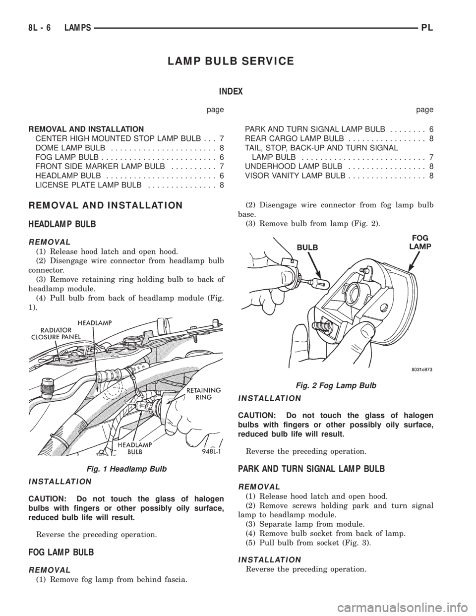
(1) Release hood latch and open hood.
(2) Disengage wire connector from headlamp bulb
connector.
(3) Remove retaining ring holding bulb to back of
headlamp module.
(4) Pull bulb from back of headlamp module (Fig.
1).
INSTALLATION
CAUTION: Do not touch the glass of halogen
bulbs with fingers or other possibly oily surface,
reduced bulb life will result.
Reverse the preceding operation.
FOG LAMP BULB
REMOVAL
(1) Remove fog lamp from behind fascia.(2) Disengage wire connector from fog lamp bulb
base.
(3) Remove bulb from lamp (Fig. 2).
INSTALLATION
CAUTION: Do not touch the glass of halogen
bulbs with fingers or other possibly oily surface,
reduced bulb life will result.
Reverse the preceding operation.
PARK AND TURN SIGNAL LAMP BULB
REMOVAL
(1) Release hood latch and open hood.
(2) Remove screws holding park and turn signal
lamp to headlamp module.
(3) Separate lamp from module.
(4) Remove bulb socket from back of lamp.
(5) Pull bulb from socket (Fig. 3).
INSTALLATION
Reverse the preceding operation.
Fig. 1 Headlamp Bulb
Fig. 2 Fog Lamp Bulb
8L - 6 LAMPSPL
Page 336 of 1200
FRONT SIDE MARKER LAMP BULB
REMOVAL
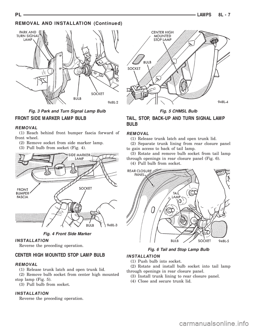
(1) Reach behind front bumper fascia forward of
front wheel.
(2) Remove socket from side marker lamp.
(3) Pull bulb from socket (Fig. 4).
INSTALLATION
Reverse the preceding operation.
CENTER HIGH MOUNTED STOP LAMP BULB
REMOVAL
(1) Release trunk latch and open trunk lid.
(2) Remove bulb socket from center high mounted
stop lamp (Fig. 5).
(3) Pull bulb from socket.
INSTALLATION
Reverse the preceding operation.
TAIL, STOP, BACK-UP AND TURN SIGNAL LAMP
BULB
REMOVAL
(1) Release trunk latch and open trunk lid.
(2) Separate trunk lining from rear closure panel
to gain access to back of tail lamp.
(3) Rotate and remove bulb socket from tail lamp
through openings in rear closure panel (Fig. 6).
(4) Pull bulb from socket.
INSTALLATION
(1) Push bulb into socket.
(2) Rotate and install bulb socket into tail lamp
through openings in rear closure panel.
(3) Install trunk lining to rear closure panel.
(4) Close and secure trunk lid.
Fig. 3 Park and Turn Signal Lamp Bulb
Fig. 4 Front Side Marker
Fig. 5 CHMSL Bulb
Fig. 6 Tail and Stop Lamp Bulb
PLLAMPS 8L - 7
REMOVAL AND INSTALLATION (Continued)