1999 DODGE NEON turn signal
[x] Cancel search: turn signalPage 875 of 1200
FUEL INJECTORSÐPCM OUTPUT
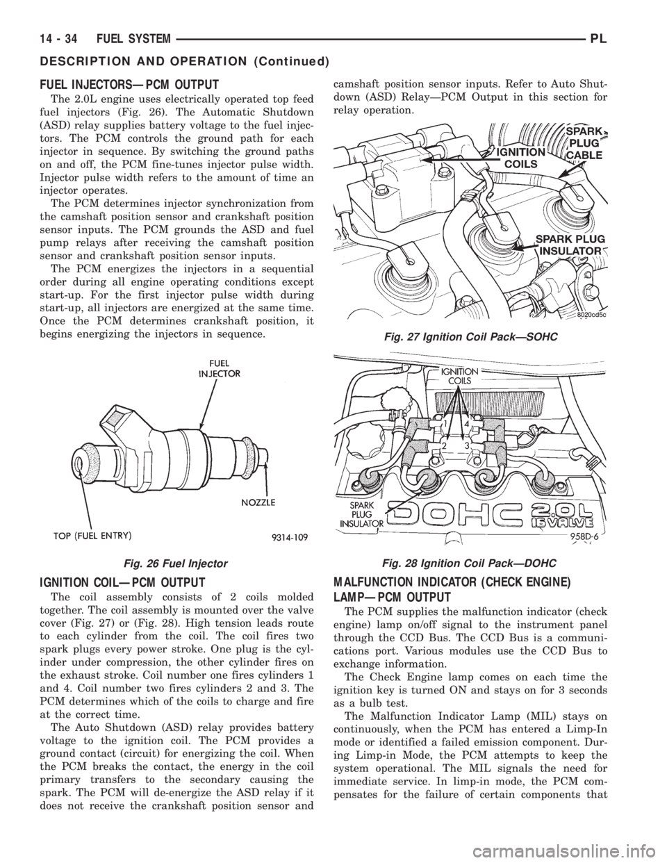
The 2.0L engine uses electrically operated top feed
fuel injectors (Fig. 26). The Automatic Shutdown
(ASD) relay supplies battery voltage to the fuel injec-
tors. The PCM controls the ground path for each
injector in sequence. By switching the ground paths
on and off, the PCM fine-tunes injector pulse width.
Injector pulse width refers to the amount of time an
injector operates.
The PCM determines injector synchronization from
the camshaft position sensor and crankshaft position
sensor inputs. The PCM grounds the ASD and fuel
pump relays after receiving the camshaft position
sensor and crankshaft position sensor inputs.
The PCM energizes the injectors in a sequential
order during all engine operating conditions except
start-up. For the first injector pulse width during
start-up, all injectors are energized at the same time.
Once the PCM determines crankshaft position, it
begins energizing the injectors in sequence.
IGNITION COILÐPCM OUTPUT
The coil assembly consists of 2 coils molded
together. The coil assembly is mounted over the valve
cover (Fig. 27) or (Fig. 28). High tension leads route
to each cylinder from the coil. The coil fires two
spark plugs every power stroke. One plug is the cyl-
inder under compression, the other cylinder fires on
the exhaust stroke. Coil number one fires cylinders 1
and 4. Coil number two fires cylinders 2 and 3. The
PCM determines which of the coils to charge and fire
at the correct time.
The Auto Shutdown (ASD) relay provides battery
voltage to the ignition coil. The PCM provides a
ground contact (circuit) for energizing the coil. When
the PCM breaks the contact, the energy in the coil
primary transfers to the secondary causing the
spark. The PCM will de-energize the ASD relay if it
does not receive the crankshaft position sensor andcamshaft position sensor inputs. Refer to Auto Shut-
down (ASD) RelayÐPCM Output in this section for
relay operation.
MALFUNCTION INDICATOR (CHECK ENGINE)
LAMPÐPCM OUTPUT
The PCM supplies the malfunction indicator (check
engine) lamp on/off signal to the instrument panel
through the CCD Bus. The CCD Bus is a communi-
cations port. Various modules use the CCD Bus to
exchange information.
The Check Engine lamp comes on each time the
ignition key is turned ON and stays on for 3 seconds
as a bulb test.
The Malfunction Indicator Lamp (MIL) stays on
continuously, when the PCM has entered a Limp-In
mode or identified a failed emission component. Dur-
ing Limp-in Mode, the PCM attempts to keep the
system operational. The MIL signals the need for
immediate service. In limp-in mode, the PCM com-
pensates for the failure of certain components that
Fig. 26 Fuel Injector
Fig. 27 Ignition Coil PackÐSOHC
Fig. 28 Ignition Coil PackÐDOHC
14 - 34 FUEL SYSTEMPL
DESCRIPTION AND OPERATION (Continued)
Page 876 of 1200

send incorrect signals. The PCM substitutes for the
incorrect signals with inputs from other sensors.
If the PCM detects active engine misfire severe
enough to cause catalyst damage, it flashes the MIL.
At the same time the PCM also sets a Diagnostic
Trouble Code (DTC).
For signals that can trigger the MIL (Check
Engine Lamp) refer to Group 25, On-Board
Dianostics.
SOLID STATE FAN RELAYÐPCM OUTPUT
The radiator fan runs when coolant temperature
and A/C system pressure demand cooling. The radia-
tor fan circuit contains a Solid State Fan Relay
(SSFR). Refer to the Group 8W for a circuit sche-
matic.
A 5 volt signal is supplied to the SSFR. The PCM
provides a pulsed ground for the SSFR. Depending
upon the amount of pulse on time, the SSFR puts out
a proportional voltage to the fan motor at the lower
speed. For instance, if the on time is 30 percent, then
the voltage to the fan motor will be 3.6 volts.
When engine coolant reaches approximately 99ÉC
(210ÉF) the PCM grounds the SSFR relay. When the
PCM grounds the relay it operates at a 30% duty
cycle and immediately ramps up to 100% duty cycle.
The PCM de-energizes the SSFR relay when coolant
temperature drops to approximately 93ÉC (199ÉF).
Also, when the air conditioning pressure switch
closes, the PCM grounds the SSFR. The air condi-
tioning switch closes at 285 psi610 psi. When air
conditioning pressure drops approximately 40 psi, the
pressure switch opens and the fan turns off.
The SSFR relay is located on the left front inner
frame just behind the radiator.
SPEED CONTROLÐPCM INPUT
The speed control system provides five separate
voltages (inputs) to the Powertrain Control Module
(PCM). The voltages correspond to the ON/OFF, SET,
RESUME and CANCEL.
The speed control ON voltage informs the PCM
that the speed control system has been activated.
The speed control SET voltage informs the PCM that
a fixed vehicle speed has been selected. The speed
control RESUME voltage indicates the previous fixed
speed is requested. The speed control CANCEL volt-
age tells the PCM to deactivate but retain set speed
in memory (same as depressing the brake pedal). The
speed control OFF voltage tells the PCM that the
speed control system has deactivated. Refer to Group
8H for more speed control information.
SCI RECEIVEÐPCM OUTPUT
SCI Receive is the serial data communication
receive circuit for the DRB scan tool. The Powertrain
Control Module (PCM) receives data from the DRB
through the SCI Receive circuit.
TACHOMETERÐPCM OUTPUT
The PCM operates the tachometer on the instru-
ment panel. The PCM calculates engine RPM from
the crankshaft position sensor input.
TORQUE CONVERTOR CLUTCH SOLENOIDÐPCM
OUTPUT
Three-speed automatic transaxles use a torque con-
verter clutch solenoid. The PCM controls the engage-
ment of the torque converter clutch through the
solenoid (Fig. 29). The torque converter clutch is
engaged up only in direct drive mode. Refer to Group
21 for transmission information.
DIAGNOSIS AND TESTING
VISUAL INSPECTIONÐSOHC
Before diagnosing or servicing the fuel injection
system, perform a visual inspection for loose, discon-
nected, or misrouted wires and hoses (Fig. 30). A
thorough visual inspection that includes the following
checks saves unnecessary test and diagnostic time.
(1) Inspect the battery connections. Clean corroded
terminals (Fig. 31).
(2) Check the 2 PCM 40-way connector for
stretched wires on pushed out terminals (Fig. 31).
Fig. 29 Torque Convertor Clutch Solenoid
PLFUEL SYSTEM 14 - 35
DESCRIPTION AND OPERATION (Continued)
Page 913 of 1200
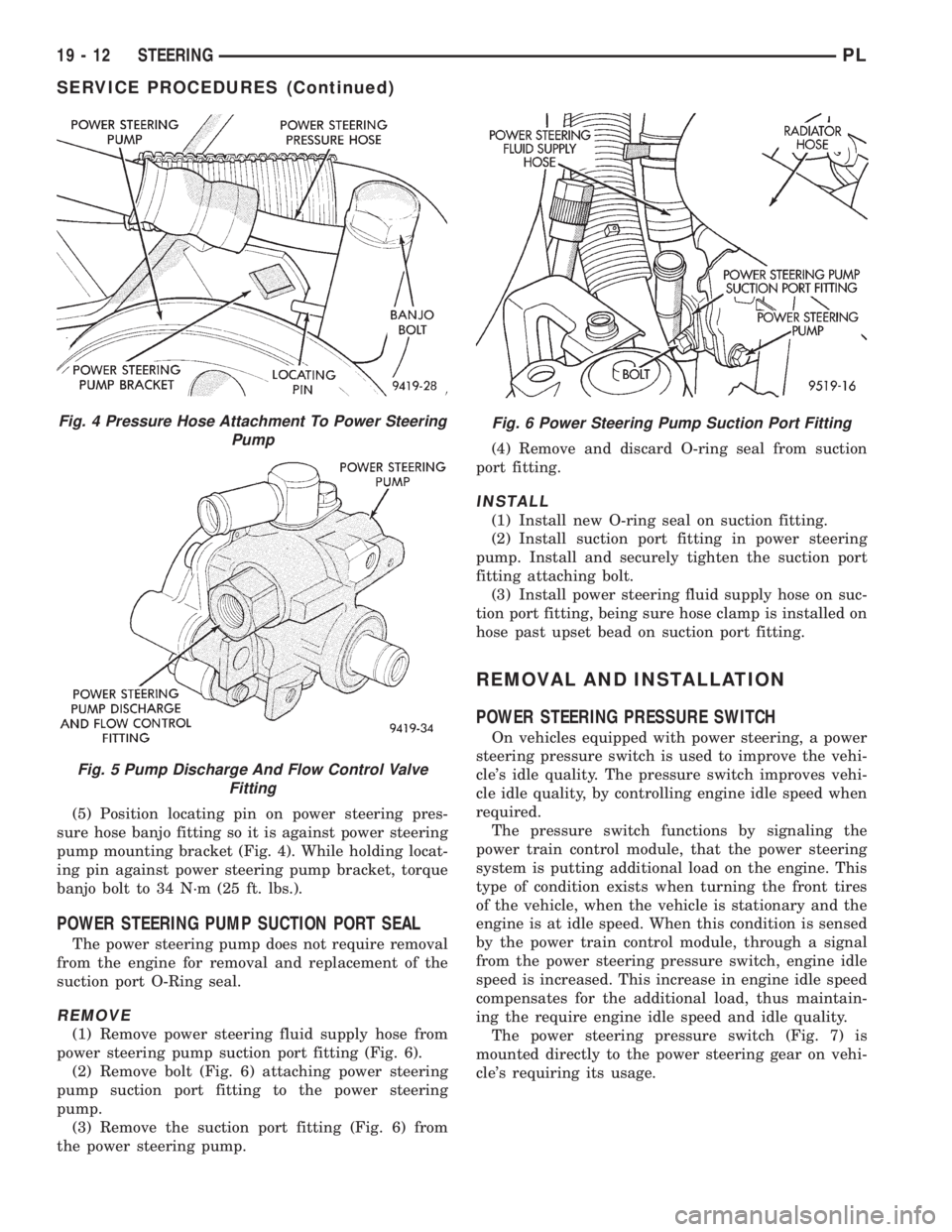
(5) Position locating pin on power steering pres-
sure hose banjo fitting so it is against power steering
pump mounting bracket (Fig. 4). While holding locat-
ing pin against power steering pump bracket, torque
banjo bolt to 34 N´m (25 ft. lbs.).
POWER STEERING PUMP SUCTION PORT SEAL
The power steering pump does not require removal
from the engine for removal and replacement of the
suction port O-Ring seal.
REMOVE
(1) Remove power steering fluid supply hose from
power steering pump suction port fitting (Fig. 6).
(2) Remove bolt (Fig. 6) attaching power steering
pump suction port fitting to the power steering
pump.
(3) Remove the suction port fitting (Fig. 6) from
the power steering pump.(4) Remove and discard O-ring seal from suction
port fitting.
INSTALL
(1) Install new O-ring seal on suction fitting.
(2) Install suction port fitting in power steering
pump. Install and securely tighten the suction port
fitting attaching bolt.
(3) Install power steering fluid supply hose on suc-
tion port fitting, being sure hose clamp is installed on
hose past upset bead on suction port fitting.
REMOVAL AND INSTALLATION
POWER STEERING PRESSURE SWITCH
On vehicles equipped with power steering, a power
steering pressure switch is used to improve the vehi-
cle's idle quality. The pressure switch improves vehi-
cle idle quality, by controlling engine idle speed when
required.
The pressure switch functions by signaling the
power train control module, that the power steering
system is putting additional load on the engine. This
type of condition exists when turning the front tires
of the vehicle, when the vehicle is stationary and the
engine is at idle speed. When this condition is sensed
by the power train control module, through a signal
from the power steering pressure switch, engine idle
speed is increased. This increase in engine idle speed
compensates for the additional load, thus maintain-
ing the require engine idle speed and idle quality.
The power steering pressure switch (Fig. 7) is
mounted directly to the power steering gear on vehi-
cle's requiring its usage.
Fig. 4 Pressure Hose Attachment To Power Steering
Pump
Fig. 5 Pump Discharge And Flow Control Valve
Fitting
Fig. 6 Power Steering Pump Suction Port Fitting
19 - 12 STEERINGPL
SERVICE PROCEDURES (Continued)
Page 942 of 1200
(23) Remove steering column from vehicle through
the drivers door of the passenger compartment. Use
care to avoid damaging the paint or interior trim.
INSTALL
(1) Install steering column into steering column
access opening in lower instrument panel.
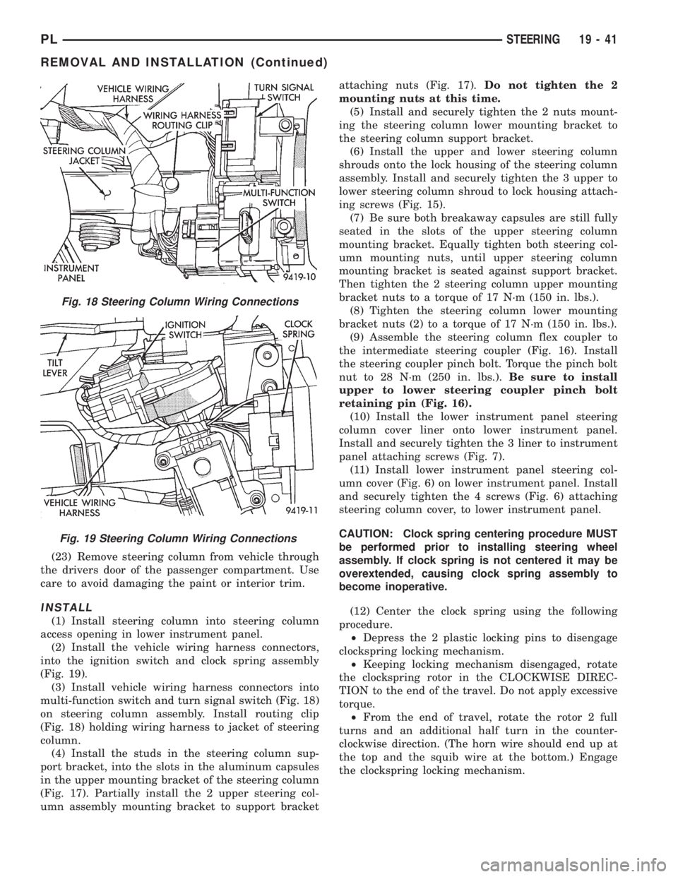
(2) Install the vehicle wiring harness connectors,
into the ignition switch and clock spring assembly
(Fig. 19).
(3) Install vehicle wiring harness connectors into
multi-function switch and turn signal switch (Fig. 18)
on steering column assembly. Install routing clip
(Fig. 18) holding wiring harness to jacket of steering
column.
(4) Install the studs in the steering column sup-
port bracket, into the slots in the aluminum capsules
in the upper mounting bracket of the steering column
(Fig. 17). Partially install the 2 upper steering col-
umn assembly mounting bracket to support bracketattaching nuts (Fig. 17).Do not tighten the 2
mounting nuts at this time.
(5) Install and securely tighten the 2 nuts mount-
ing the steering column lower mounting bracket to
the steering column support bracket.
(6) Install the upper and lower steering column
shrouds onto the lock housing of the steering column
assembly. Install and securely tighten the 3 upper to
lower steering column shroud to lock housing attach-
ing screws (Fig. 15).
(7) Be sure both breakaway capsules are still fully
seated in the slots of the upper steering column
mounting bracket. Equally tighten both steering col-
umn mounting nuts, until upper steering column
mounting bracket is seated against support bracket.
Then tighten the 2 steering column upper mounting
bracket nuts to a torque of 17 N´m (150 in. lbs.).
(8) Tighten the steering column lower mounting
bracket nuts (2) to a torque of 17 N´m (150 in. lbs.).
(9) Assemble the steering column flex coupler to
the intermediate steering coupler (Fig. 16). Install
the steering coupler pinch bolt. Torque the pinch bolt
nut to 28 N´m (250 in. lbs.).Be sure to install
upper to lower steering coupler pinch bolt
retaining pin (Fig. 16).
(10) Install the lower instrument panel steering
column cover liner onto lower instrument panel.
Install and securely tighten the 3 liner to instrument
panel attaching screws (Fig. 7).
(11) Install lower instrument panel steering col-
umn cover (Fig. 6) on lower instrument panel. Install
and securely tighten the 4 screws (Fig. 6) attaching
steering column cover, to lower instrument panel.
CAUTION: Clock spring centering procedure MUST
be performed prior to installing steering wheel
assembly. If clock spring is not centered it may be
overextended, causing clock spring assembly to
become inoperative.
(12) Center the clock spring using the following
procedure.
²Depress the 2 plastic locking pins to disengage
clockspring locking mechanism.
²Keeping locking mechanism disengaged, rotate
the clockspring rotor in the CLOCKWISE DIREC-
TION to the end of the travel. Do not apply excessive
torque.
²From the end of travel, rotate the rotor 2 full
turns and an additional half turn in the counter-
clockwise direction. (The horn wire should end up at
the top and the squib wire at the bottom.) Engage
the clockspring locking mechanism.
Fig. 18 Steering Column Wiring Connections
Fig. 19 Steering Column Wiring Connections
PLSTEERING 19 - 41
REMOVAL AND INSTALLATION (Continued)
Page 1173 of 1200
FUEL PRESSURE
The fuel pressure regulator controls fuel system
pressure. The PCM cannot detect a clogged fuel
pump inlet filter, clogged in-line fuel filter, or a
pinched fuel supply or return line. However, these
could result in a rich or lean condition causing the
PCM to store an oxygen sensor or fuel system diag-
nostic trouble code.
SECONDARY IGNITION CIRCUIT
The PCM cannot detect an inoperative ignition coil,
fouled or worn spark plugs, ignition cross firing, or
open spark plug cables.
CYLINDER COMPRESSION
The PCM cannot detect uneven, low, or high engine
cylinder compression.
EXHAUST SYSTEM
The PCM cannot detect a plugged, restricted or
leaking exhaust system. It may set a EGR or Fuel
system fault or O2S.
FUEL INJECTOR MECHANICAL
MALFUNCTIONS
The PCM cannot determine if a fuel injector is
clogged, the needle is sticking or if the wrong injector
is installed. However, these could result in a rich or
lean condition causing the PCM to store a diagnostic
trouble code for either misfire, an oxygen sensor, or
the fuel system.
EXCESSIVE OIL CONSUMPTION
Although the PCM monitors engine exhaust oxygen
content when the system is in closed loop, it cannot
determine excessive oil consumption.
THROTTLE BODY AIR FLOW
The PCM cannot detect a clogged or restricted air
cleaner inlet or filter element.
VACUUM ASSIST
The PCM cannot detect leaks or restrictions in the
vacuum circuits of vacuum assisted engine control
system devices. However, these could cause the PCM
to store a MAP sensor diagnostic trouble code and
cause a high idle condition.
PCM SYSTEM GROUND
The PCM cannot determine a poor system ground.
However, one or more diagnostic trouble codes may
be generated as a result of this condition. The mod-
ule should be mounted to the body at all times, also
during diagnostic.
PCM CONNECTOR ENGAGEMENT
The PCM may not be able to determine spread or
damaged connector pins. However, it might store
diagnostic trouble codes as a result of spread connec-
tor pins.
HIGH AND LOW LIMITS
The PCM compares input signal voltages from each
input device with established high and low limits for
the device. If the input voltage is not within limits
and other criteria are met, the PCM stores a diagnos-
tic trouble code in memory. Other diagnostic trouble
code criteria might include engine RPM limits or
input voltages from other sensors or switches that
must be present before verifying a diagnostic trouble
code condition.
LOAD VALUE
ENGINE IDLE/NEUTRAL 2500 RPM/NEUTRAL
2.0L SOHC 2% to 8% of Maximum Load 8% to 15% of Maximum Load
2.4L DOHC 2% to 8% of Maximum Load 7% to 15% of Maximum Load
2.5L SOHC 2% to 8% of Maximum Load 7% to 15% of Maximum Load
25 - 10 EMISSION CONTROL SYSTEMSPL
DESCRIPTION AND OPERATION (Continued)
Page 1182 of 1200
DIAGNOSIS AND TESTING
EGR SYSTEM ON-BOARD DIAGNOSTICS
The PCM performs an on-board diagnostic check of
the EGR system. The diagnostic system uses the
electronic EGR transducer for the system tests.
The diagnostic check activates only during selected
engine/driving conditions. When the conditions are
met, the PCM energizes the transducer solenoid to
disable the EGR. The PCM checks for a change in
the heated oxygen sensor signal. If the air-fuel mix-
ture goes lean, the PCM will attempt to enrichen the
mixture. The PCM registers a Diagnostic Trouble
Code (DTC) if the EGR system is not operating cor-
rectly. After registering a DTC, the PCM turns on the
malfunction indicator (Check Engine) lamp after 2
consecutive trips. There are 2 types of failures sensed
by the PCM. The first is a short or open in the elec-
trical solenoid circuit. the second is a mechhanical
failure or loss of vacuum. The Malfunction Indicator
Lamp (MIL) indicates the need for service.
If a problem is indicated by the MIL and a DTC for
the EGR system is set, check for proper operation of
the EGR system. Use the System Test, EGR Gas
Flow Test. If the EGR system tests properly, check
the system using the DRB scan tool. Refer to
On-Board Diagnosis sections in this Group. Also,
refer to the DRB scan tool and the appropriate Pow-
ertrain Diagnostics Procedure manual.
EGR SYSTEM TEST
WARNING: APPLY PARKING BRAKE AND/OR
BLOCK WHEELS BEFORE TESTING THE EGR SYS-
TEM.
(1) Check the condition of all EGR system hoses
and tubes for leaks, blockages, cracks, kinks and
hardening of rubber hoses. Repair and correct these
conditions before performing any tests.
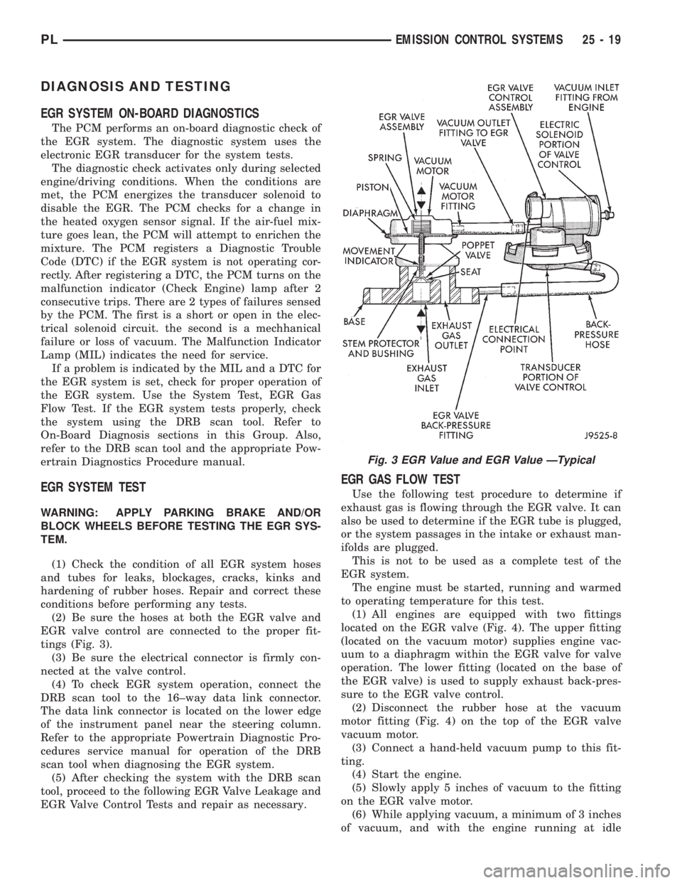
(2) Be sure the hoses at both the EGR valve and
EGR valve control are connected to the proper fit-
tings (Fig. 3).
(3) Be sure the electrical connector is firmly con-
nected at the valve control.
(4) To check EGR system operation, connect the
DRB scan tool to the 16±way data link connector.
The data link connector is located on the lower edge
of the instrument panel near the steering column.
Refer to the appropriate Powertrain Diagnostic Pro-
cedures service manual for operation of the DRB
scan tool when diagnosing the EGR system.
(5) After checking the system with the DRB scan
tool, proceed to the following EGR Valve Leakage and
EGR Valve Control Tests and repair as necessary.
EGR GAS FLOW TEST
Use the following test procedure to determine if
exhaust gas is flowing through the EGR valve. It can
also be used to determine if the EGR tube is plugged,
or the system passages in the intake or exhaust man-
ifolds are plugged.
This is not to be used as a complete test of the
EGR system.
The engine must be started, running and warmed
to operating temperature for this test.
(1) All engines are equipped with two fittings
located on the EGR valve (Fig. 4). The upper fitting
(located on the vacuum motor) supplies engine vac-
uum to a diaphragm within the EGR valve for valve
operation. The lower fitting (located on the base of
the EGR valve) is used to supply exhaust back-pres-
sure to the EGR valve control.
(2) Disconnect the rubber hose at the vacuum
motor fitting (Fig. 4) on the top of the EGR valve
vacuum motor.
(3) Connect a hand-held vacuum pump to this fit-
ting.
(4) Start the engine.
(5) Slowly apply 5 inches of vacuum to the fitting
on the EGR valve motor.
(6) While applying vacuum, a minimum of 3 inches
of vacuum, and with the engine running at idle
Fig. 3 EGR Value and EGR Value ÐTypical
PLEMISSION CONTROL SYSTEMS 25 - 19
Page 1200 of 1200
GROUP TAB LOCATOR
INIntroduction
INaIntroduction
0Lubrication and Maintenance
2Suspension
3Differential and Driveline
5Brakes
6Clutch
6aClutch
7Cooling
8ABattery
8BStarting
8CCharging System
8CaCharging System
8DIgnition System
8EInstrument Panel and Systems
8EaInstrument Panel and Systems
8FAudio System
8GHorns
8HVehicle Speed Control System
8HaVehicle Speed Control System
8JTurn Signal and Flashers
8KWindshield Wipers and Washers
8KaWindshield Wipers and Washers
8LLamps
8LaLamps
8MRestraint System
8NElectrically Heated Systems
8NaElectrically Heated Systems
8PPower Door Locks
8QaImmobilizer System
8SPower Windows
8TPower Mirrors
8TaPower Mirrors
8UChime Warning/Reminder System
8WWiring Diagrams - LHD and RHD
9Engine
9aEngine
11Exhaust System and Intake Manifold
11aExhaust System and Intake Manifold
13Frame and Bumpers
13aFrame and Bumpers
14Fuel System
14aFuel System - 1.8L Engine
19Steering
19aSteering
21Transaxle
21aTransaxle
22Tires and Wheels
23Body
24Heating and Air Conditioning
25Emission Control Systems
25aEmission Control System - 1.8L Engine