1999 DODGE NEON turn signal
[x] Cancel search: turn signalPage 678 of 1200
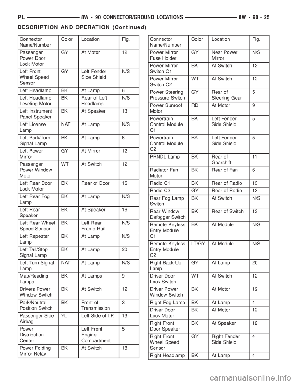
Connector
Name/NumberColor Location Fig.
Passenger
Power Door
Lock MotorGY At Motor 12
Left Front
Wheel Speed
SensorGY Left Fender
Side ShieldN/S
Left Headlamp BK At Lamp 6
Left Headlamp
Leveling MotorBK Rear of Left
HeadlampN/S
Left Instrument
Panel SpeakerBK At Speaker 13
Left License
LampNAT At Lamp N/S
Left Park/Turn
Signal LampBK At Lamp 6
Left Power
MirrorGY At Mirror 12
Passenger
Power Window
MotorWT At Switch 12
Left Rear Door
Lock MotorBK Rear of Door 15
Left Rear Fog
LampBK At Lamp N/S
Left Rear
SpeakerBK At Speaker 16
Left Rear Wheel
Speed SensorBK Left Rear
Frame RailN/S
Left Repeater
LampBK At Lamp N/S
Left Tail/Stop
Signal LampBK At Lamp 20
Left Turn Signal
LampNAT At Lamp N/S
Map/Reading
LampsBK At Lamps 9
Drivers Power
Window SwitchBK At Switch 12
Park/Neutral
Position SwitchBK Front of
Transmission3
Passenger Side
AirbagYL Left Side of I.P. 13
Power
Distribution
CenterLeft Front
Engine
Compartment5
Power Folding
Mirror RelayBK At Switch 18Connector
Name/NumberColor Location Fig.
Power Mirror
Fuse HolderGY Near Power
MirrorN/S
Power Mirror
Switch C1BK At Switch 12
Power Mirror
Switch C2WT At Switch 12
Power Steering
Pressure SwitchGY Rear of
Steering Gear5
Power Sunroof
MotorRD At Motor 9
Powertrain
Control Module
C1BK Left Fender
Side Shield5
Powertrain
Control Module
C2BK Left Fender
Side Shield5
PRNDL Lamp BK Rear of
Gearshift11
Radiator Fan
MotorBK Rear of Fan 6
Radio C1 BK Rear of Radio 13
Radio C2 GY Rear of Radio 13
Rear Fog Lamp
SwitchBK At Switch N/S
Rear Window
Defogger SwitchBK Rear of Switch 13
Remote Keyless
Entry Module
C1BK At Module N/S
Remote Keyless
Entry Module
C2LT/GY At Module N/S
Right Back-Up
LampGY At Lamp 20
Driver Door
Lock SwitchWT At Switch 12
Driver Power
Window SwitchBK At Motor 12
RIght Fog Lamp BK At Lamp 4
Driver Door
Lock MotorBK At Motor 12
Right Front
Door SpeakerBK At Speaker 12
Right Front
Wheel Speed
SensorGY Right Fender
Side Shield4
Right Headlamp BK At Lamp 4
PL8W - 90 CONNECTOR/GROUND LOCATIONS 8W - 90 - 25
DESCRIPTION AND OPERATION (Continued)
Page 679 of 1200
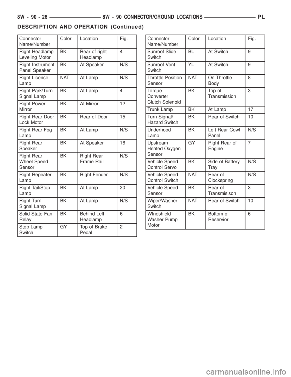
Connector
Name/NumberColor Location Fig.
Right Headlamp
Leveling MotorBK Rear of right
Headlamp4
Right Instrument
Panel SpeakerBK At Speaker N/S
Right License
LampNAT At Lamp N/S
Right Park/Turn
Signal LampBK At Lamp 4
Right Power
MirrorBK At Mirror 12
Right Rear Door
Lock MotorBK Rear of Door 15
Right Rear Fog
LampBK At Lamp N/S
Right Rear
SpeakerBK At Speaker 16
Right Rear
Wheel Speed
SensorBK Right Rear
Frame RailN/S
Right Repeater
LampBK Right Fender N/S
Right Tail/Stop
LampBK At Lamp 20
Right Turn
Signal LampBK At Lamp N/S
Solid State Fan
RelayBK Behind Left
Headlamp6
Stop Lamp
SwitchGY Top of Brake
Pedal2Connector
Name/NumberColor Location Fig.
Sunroof Slide
SwitchBL At Switch 9
Sunroof Vent
SwitchYL At Switch 9
Throttle Position
SensorNAT On Throttle
Body8
Torque
Converter
Clutch SolenoidBK Top of
Transmission3
Trunk Lamp BK At Lamp 17
Turn Signal/
Hazard SwitchBK Rear of Switch 10
Underhood
LampBK Left Rear Cowl
PanelN/S
Upstream
Heated Oxygen
SensorGY Right Rear of
Engine7
Vehicle Speed
Control ServoBK Side of Battery
TrayN/S
Vehicle Speed
Control SwitchNAT Rear of
ClockspringN/S
Vehicle Speed
SensorBK Rear of
Transmisison3
Wiper/Washer
SwitchNAT Rear of Switch 10
WIndshield
Washer Pump
MotorBK Bottom of
Reservior6
8W - 90 - 26 8W - 90 CONNECTOR/GROUND LOCATIONSPL
DESCRIPTION AND OPERATION (Continued)
Page 845 of 1200
ELECTRIC FUEL PUMP
The electric fuel pump is located in and is part of
the fuel pump module. It is a positive displacement,
gerotor type, immersible pump with a permanent
magnet electric motor. The fuel pump module is sus-
pended in fuel in the fuel tank. The pump draws fuel
through a strainer and pushes it through the motor
to the outlet. The pump contains a check valve. The
valve, in the pump outlet, maintains pump pressure
during engine off conditions. The fuel pump relay
provides voltage to the fuel pump.
The fuel pump has a maximum deadheaded pres-
sure output of approximately 880 kPa (130 psi). The
regulator adjusts fuel system pressure to approxi-
mately 338 kPa (49 psi).
FUEL GAUGE SENDING UNIT
The fuel gauge sending unit (fuel level sensor) is
attached to the side of the fuel pump module. The
sending unit consists of a float, an arm, and a vari-
able resistor (track). The resistor track is used to
send electrical signals to the Powertrain Control
Module (PCM) for fuel gauge operation and for OBD
II emission requirements.
For fuel gauge operation:As fuel level
increases, the float and arm move up. This decreases
the sending unit resistance, causing the fuel gauge to
read full. As fuel level decreases, the float and arm
move down. This increases the sending unit resis-
tance causing the fuel gauge to read empty.
After this fuel level signal is sent to the PCM, the
PCM will transmit the data across the CCD bus cir-
cuits to the instrument panel. Here it is translated
into the appropriate fuel gauge level reading.
FUEL FILTER/FUEL PRESSURE REGULATOR
A combination fuel filter and fuel pressure regula-
tor is used on all gas powered engines. It is located
on the top of the fuel pump module. A separate frame
mounted fuel filter is not used.
Fuel Pressure Regulator Operation:The pres-
sure regulator is a mechanical device that is cali-
brated to maintain fuel system operating pressure of
approximately 338 kPa (49 psi) at the fuel injectors.
It contains a diaphragm, calibrated springs and a
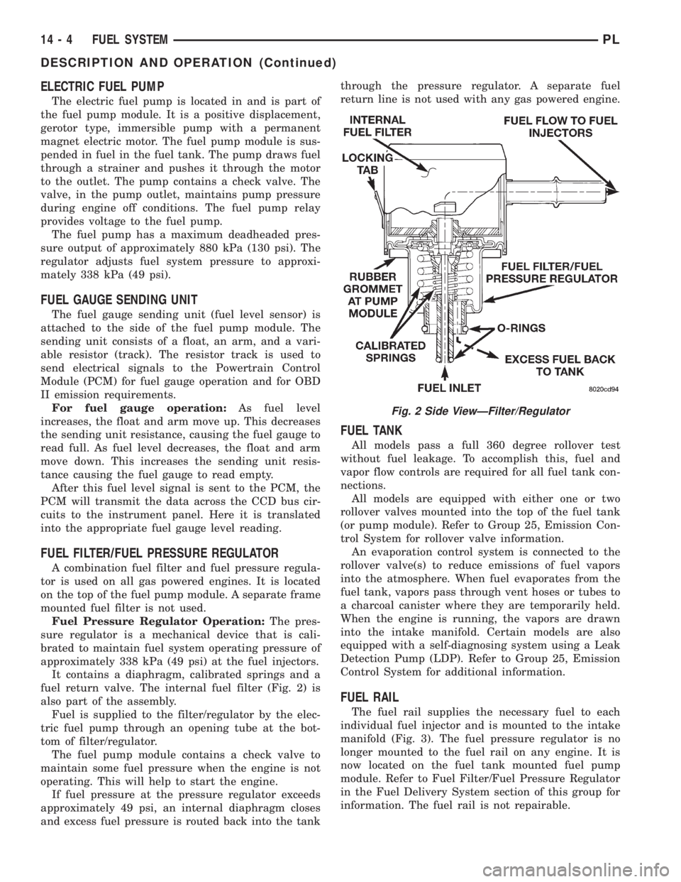
fuel return valve. The internal fuel filter (Fig. 2) is
also part of the assembly.
Fuel is supplied to the filter/regulator by the elec-
tric fuel pump through an opening tube at the bot-
tom of filter/regulator.
The fuel pump module contains a check valve to
maintain some fuel pressure when the engine is not
operating. This will help to start the engine.
If fuel pressure at the pressure regulator exceeds
approximately 49 psi, an internal diaphragm closes
and excess fuel pressure is routed back into the tankthrough the pressure regulator. A separate fuel
return line is not used with any gas powered engine.
FUEL TANK
All models pass a full 360 degree rollover test
without fuel leakage. To accomplish this, fuel and
vapor flow controls are required for all fuel tank con-
nections.
All models are equipped with either one or two
rollover valves mounted into the top of the fuel tank
(or pump module). Refer to Group 25, Emission Con-
trol System for rollover valve information.
An evaporation control system is connected to the
rollover valve(s) to reduce emissions of fuel vapors
into the atmosphere. When fuel evaporates from the
fuel tank, vapors pass through vent hoses or tubes to
a charcoal canister where they are temporarily held.
When the engine is running, the vapors are drawn
into the intake manifold. Certain models are also
equipped with a self-diagnosing system using a Leak
Detection Pump (LDP). Refer to Group 25, Emission
Control System for additional information.
FUEL RAIL
The fuel rail supplies the necessary fuel to each
individual fuel injector and is mounted to the intake
manifold (Fig. 3). The fuel pressure regulator is no
longer mounted to the fuel rail on any engine. It is
now located on the fuel tank mounted fuel pump
module. Refer to Fuel Filter/Fuel Pressure Regulator
in the Fuel Delivery System section of this group for
information. The fuel rail is not repairable.
Fig. 2 Side ViewÐFilter/Regulator
14 - 4 FUEL SYSTEMPL
DESCRIPTION AND OPERATION (Continued)
Page 847 of 1200
DIAGNOSIS AND TESTING
FUEL PUMP PRESSURE TEST
The fuel system operates at approximately 338 kPa
(49 psi). Check fuel system pressure at the test port
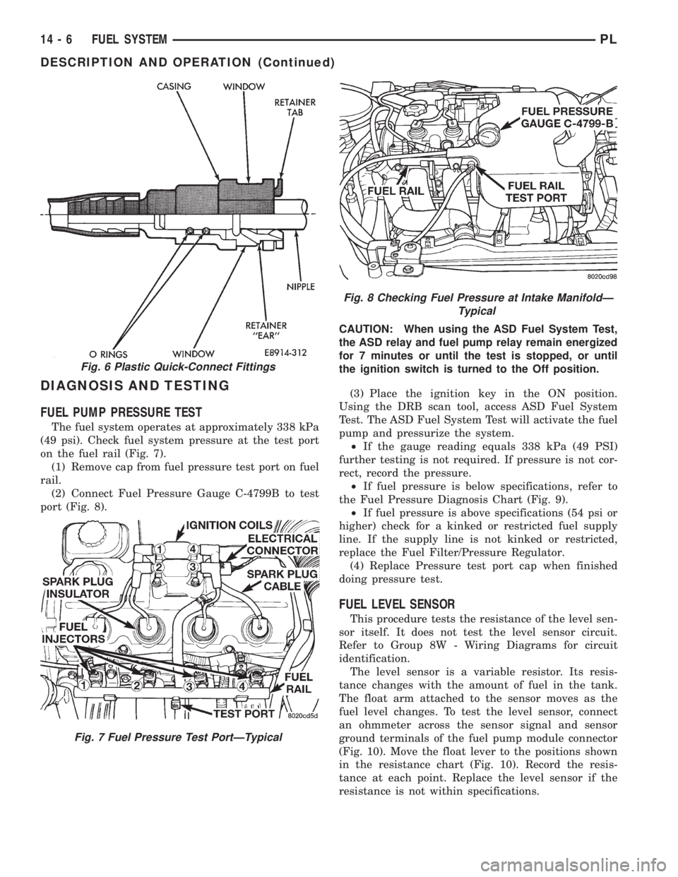
on the fuel rail (Fig. 7).
(1) Remove cap from fuel pressure test port on fuel
rail.
(2) Connect Fuel Pressure Gauge C-4799B to test
port (Fig. 8).CAUTION: When using the ASD Fuel System Test,
the ASD relay and fuel pump relay remain energized
for 7 minutes or until the test is stopped, or until
the ignition switch is turned to the Off position.
(3) Place the ignition key in the ON position.
Using the DRB scan tool, access ASD Fuel System
Test. The ASD Fuel System Test will activate the fuel
pump and pressurize the system.
²If the gauge reading equals 338 kPa (49 PSI)
further testing is not required. If pressure is not cor-
rect, record the pressure.
²If fuel pressure is below specifications, refer to
the Fuel Pressure Diagnosis Chart (Fig. 9).
²If fuel pressure is above specifications (54 psi or
higher) check for a kinked or restricted fuel supply
line. If the supply line is not kinked or restricted,
replace the Fuel Filter/Pressure Regulator.
(4) Replace Pressure test port cap when finished
doing pressure test.
FUEL LEVEL SENSOR
This procedure tests the resistance of the level sen-
sor itself. It does not test the level sensor circuit.
Refer to Group 8W - Wiring Diagrams for circuit
identification.
The level sensor is a variable resistor. Its resis-
tance changes with the amount of fuel in the tank.
The float arm attached to the sensor moves as the
fuel level changes. To test the level sensor, connect
an ohmmeter across the sensor signal and sensor
ground terminals of the fuel pump module connector
(Fig. 10). Move the float lever to the positions shown
in the resistance chart (Fig. 10). Record the resis-
tance at each point. Replace the level sensor if the
resistance is not within specifications.
Fig. 8 Checking Fuel Pressure at Intake ManifoldÐ
Typical
Fig. 6 Plastic Quick-Connect Fittings
Fig. 7 Fuel Pressure Test PortÐTypical
14 - 6 FUEL SYSTEMPL
DESCRIPTION AND OPERATION (Continued)
Page 863 of 1200

ENGINE START-UP MODE
This is an OPEN LOOP mode. If the vehicle is in
park or neutral (automatic transaxles) or the clutch
pedal is depressed (manual transaxles) the ignition
switch energizes the starter relay. The following
actions occur when the starter motor is engaged.
²If the PCM receives the camshaft position sensor
and crankshaft position sensor signals, it energizes
the Auto Shutdown (ASD) and fuel pump relays. If
the PCM does not receive both signals within approx-
imately one second, it will not energize the ASD
relay and fuel pump relay. The ASD and fuel pump
relays supply battery voltage to the fuel pump, fuel
injectors, ignition coil and heated oxygen sensors.
²The PCM energizes all four injectors (on the 69É
degree falling edge) for a calculated pulse width until
it determines crankshaft position from the camshaft
position sensor and crankshaft position sensor sig-
nals. The PCM determines crankshaft position within
1 engine revolution.
²After determining crankshaft position, the PCM
begins energizing the injectors in sequence. It adjusts
injector pulse width and controls injector synchroni-
zation by turning the individual ground paths to the
injectors On and Off.
²When the engine idles within664 RPM of its
target RPM, the PCM compares current MAP sensor
value with the atmospheric pressure value received
during the Ignition Switch On (zero RPM) mode. If
the PCM does not detect a minimum difference
between the two values, it sets a MAP diagnostic
trouble code into memory.
Once the ASD and fuel pump relays have been
energized, the PCM determines injector pulse width
based on the following:
²Battery voltage
²Engine coolant temperature
²Engine RPM
²Intake air temperature (IAT)
²Throttle position
²The number of engine revolutions since cranking
was initiated
During Start-up the PCM maintains ignition tim-
ing at 9É BTDC.
ENGINE WARM-UP MODE
This is an OPEN LOOP mode. The following inputs
are received by the PCM:
²Engine coolant temperature
²Manifold Absolute Pressure (MAP)
²Intake air temperature (IAT)
²Crankshaft position (engine speed)
²Camshaft position
²Knock sensor
²Throttle position
²A/C switch
²Battery voltage²Power steering pressure switch
²Vehicle speed
²Speed control
²Both O2 sensors
²All diagnostics
The PCM adjusts injector pulse width and controls
injector synchronization by turning the individual
ground paths to the injectors On and Off.
The PCM adjusts ignition timing and engine idle
speed. Engine idle speed is adjusted through the idle
air control motor.
CRUISE OR IDLE MODE
When the engine is at operating temperature this
is a CLOSED LOOP mode. During cruising or idle
the following inputs are received by the PCM:
²Intake air temperature
²Engine coolant temperature
²Manifold absolute pressure
²Crankshaft position (engine speed)
²Camshaft position
²Knock sensor
²Throttle position
²Exhaust gas oxygen content
²A/C control positions
²Power steering pressure switch
²Battery voltage
²Vehicle speed
The PCM adjusts injector pulse width and controls
injector synchronization by turning the individual
ground paths to the injectors On and Off.
The PCM adjusts engine idle speed and ignition
timing. The PCM adjusts the air/fuel ratio according
to the oxygen content in the exhaust gas (measured
by the upstream and downstream heated oxygen sen-
sor).
The PCM monitors for engine misfire. During
active misfire and depending on the severity, the
PCM either continuously illuminates or flashes the
malfunction indicator lamp (Check Engine light on
instrument panel). Also, the PCM stores an engine
misfire DTC in memory.
The PCM performs several diagnostic routines.
They include:
²Oxygen sensor monitor
²Downstream heated oxygen sensor diagnostics
during open loop operation (except for shorted)
²Fuel system monitor
²EGR monitor
²Purge system monitor
²All inputs monitored for proper voltage range.
²All monitored components (refer to Group 25 for
On-Board Diagnostics).
The PCM compares the upstream and downstream
heated oxygen sensor inputs to measure catalytic
convertor efficiency. If the catalyst efficiency drops
14 - 22 FUEL SYSTEMPL
GENERAL INFORMATION (Continued)
Page 865 of 1200

POWERTRAIN CONTROL MODULE
The Powertrain Control Module (PCM) is a digital
computer containing a microprocessor (Fig. 2). The
PCM receives input signals from various switches
and sensors that are referred to as PCM Inputs.
Based on these inputs, the PCM adjusts various
engine and vehicle operations through devices that
are referred to as PCM Outputs.
PCM Inputs:
²Air Conditioning Controls
²Battery Voltage
²Battery Temperature Sensor
²Brake Switch
²Camshaft Position Sensor
²Crankshaft Position Sensor
²Engine Coolant Temperature Sensor
²Fuel Level Sensor
²Ignition Switch
²Intake Air Temperature Sensor
²Knock Sensor
²Manifold Absolute Pressure (MAP) Sensor
²Oxygen Sensors
²Power Steering Pressure Switch
²SCI Receive
²Speed Control Switches
²Throttle Position Sensor
²Transmission Park/Neutral Switch (automatic
transmission)
²Vehicle Speed Sensor
PCM Outputs:
²Air Conditioning WOT Relay
²Auto Shutdown (ASD) Relay
²Charging Indicator Lamp
²Data Link Connector
²Duty Cycle EVAP Canister Purge Solenoid
²EGR Solenoid
²Fuel Injectors
²Fuel Pump Relay²Generator Field
²Idle Air Control Motor
²Ignition Coils
²Malfunction Indicator (Check Engine) Lamp
²Radiator Fan Relay
²Speed Control Solenoids
²Tachometer
²Torque Convertor Clutch Solenoid
Based on inputs it receives, the PCM adjusts fuel
injector pulse width, idle speed, ignition spark
advance, ignition coil dwell and EVAP canister purge
operation. The PCM regulates the cooling fan, air
conditioning and speed control systems. The PCM
changes generator charge rate by adjusting the gen-
erator field. The PCM also performs diagnostics.
The PCM adjusts injector pulse width (air-fuel
ratio) based on the following inputs.
²Battery voltage
²Coolant temperature
²Intake air temperature
²Exhaust gas content (oxygen sensor)
²Engine speed (crankshaft position sensor)
²Manifold absolute pressure
²Throttle position
The PCM adjusts ignition timing based on the fol-
lowing inputs.
²Coolant temperature
²Intake air temperature
²Engine speed (crankshaft position sensor)
²Knock sensor
²Manifold absolute pressure
²Throttle position
²Transmission gear selection (park/neutral
switch)
The PCM also adjusts engine idle speed through
the idle air control motor based on the following
inputs.
²Air conditioning sense
²Battery voltage
²Battery temperature
²Brake switch
²Coolant temperature
²Engine speed (crankshaft position sensor)
²Engine run time
²Manifold absolute pressure
²Power steering pressure switch
²Throttle position
²Transmission gear selection (park/neutral
switch)
²Vehicle distance (speed)
The Auto Shutdown (ASD) and fuel pump relays
are mounted externally, but turned on and off by the
PCM.
The crankshaft position sensor signal is sent to the
PCM. If the PCM does not receive the signal within
approximately one second of engine cranking, it deac-
Fig. 2 Powertrain Control Module (PCM)
14 - 24 FUEL SYSTEMPL
DESCRIPTION AND OPERATION (Continued)
Page 871 of 1200
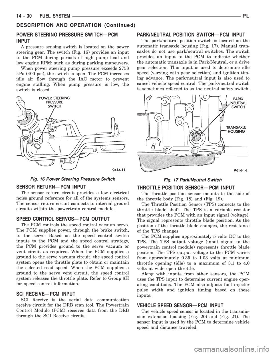
POWER STEERING PRESSURE SWITCHÐPCM
INPUT
A pressure sensing switch is located on the power
steering gear. The switch (Fig. 16) provides an input
to the PCM during periods of high pump load and
low engine RPM; such as during parking maneuvers.
When power steering pump pressure exceeds 2758
kPa (400 psi), the switch is open. The PCM increases
idle air flow through the IAC motor to prevent
engine stalling. When pump pressure is low, the
switch is closed.
SENSOR RETURNÐPCM INPUT
The sensor return circuit provides a low electrical
noise ground reference for all of the systems sensors.
The sensor return circuit connects to internal ground
circuits within the powertrain control module.
SPEED CONTROL SERVOSÐPCM OUTPUT
The PCM controls the speed control vacuum servo.
The PCM supplies power, through the brake switch,
to the servo. Based on the speed control switch
inputs to the PCM and the speed control strategy,
the PCM provides ground to the servo vacuum or
vent circuit as required. When the PCM supplies a
ground to the servo vacuum circuit, the speed control
system opens the throttle plate to obtain or maintain
the selected road speed. When the PCM supplies a
ground to the servo vent circuit, the speed control
system releases the throttle plate. Refer to Group 8H
for speed control information.
SCI RECEIVEÐPCM INPUT
SCI Receive is the serial data communication
receive circuit for the DRB scan tool. The Powertrain
Control Module (PCM) receives data from the DRB
through the SCI Receive circuit.
PARK/NEUTRAL POSITION SWITCHÐPCM INPUT
The park/neutral position switch is located on the
automatic transaxle housing (Fig. 17). Manual tran-
saxles do not use park/neutral switches. The switch
provides an input to the PCM to indicate whether
the automatic transaxle is in Park/Neutral, or a drive
gear selection. This input is used to determine idle
speed (varying with gear selection) and ignition tim-
ing advance. The park/neutral input is also used to
cancel vehicle speed control. The park/neutral switch
is sometimes referred to as the neutral safety switch.
THROTTLE POSITION SENSORÐPCM INPUT
The throttle position sensor mounts to the side of
the throttle body (Fig. 18) and (Fig. 19).
The Throttle Position Sensor (TPS) connects to the
throttle blade shaft. The TPS is a variable resistor
that provides the PCM with an input signal (voltage).
The signal represents throttle blade position. As the
position of the throttle blade changes, the resistance
of the TPS changes.
The PCM supplies approximately 5 volts DC to the
TPS. The TPS output voltage (input signal to the
powertrain control module) represents throttle blade
position. The TPS output voltage to the PCM varies
from approximately 0.35 to 1.03 volts at minimum
throttle opening (idle) to a maximum of 3.1 to 4.0
volts at wide open throttle.
Along with inputs from other sensors, the PCM
uses the TPS input to determine current engine oper-
ating conditions. The PCM also adjusts fuel injector
pulse width and ignition timing based on these
inputs.
VEHICLE SPEED SENSORÐPCM INPUT
The vehicle speed sensor is located in the transmis-
sion extension housing (Fig. 20) and (Fig. 21). The
sensor input is used by the PCM to determine vehicle
speed and distance traveled.
Fig. 16 Power Steering Pressure SwitchFig. 17 Park/Neutral Switch
14 - 30 FUEL SYSTEMPL
DESCRIPTION AND OPERATION (Continued)
Page 873 of 1200
disables the A/C compressor clutch for several sec-
onds.
The air conditioning clutch relay is located in the
PDC. The inside top of the PDC cover has a label
showing relay and fuse location.
AUTOMATIC SHUTDOWN RELAYÐPCM OUTPUT
The automatic shutdown (ASD) relay supplies bat-
tery voltage to the fuel injectors, electronic ignition
coil and the heating elements in the oxygen sensors.
A buss bar in the power distribution center (PDC)
supplies voltage to the solenoid side and contact side
of the relay. The ASD relay power circuit contains a
20 amp fuse between the buss bar in the PDC and
the relay. The fuse also protects the power circuit for
the fuel pump relay and pump. The fuse is located in
the PDC. Refer to Group 8W, Wiring Diagrams for
circuit information.
The PCM controls the relay by switching the
ground path for the solenoid side of the relay on and
off. The PCM turns the ground path off when the
ignition switch is in the Off position unless the 02
Heater Monitor test is being run. Refer to Group 25,
On-Board Diagnostics. When the ignition switch is in
the On or Crank position, the PCM monitors the
crankshaft position sensor and camshaft position sen-
sor signals to determine engine speed and ignition
timing (coil dwell). If the PCM does not receive the
crankshaft position sensor and camshaft position sen-
sor signals when the ignition switch is in the Run
position, it will de- energize the ASD relay.
The ASD relay is located in the PDC. The inside
top of the PDC cover has a label showing relay and
fuse location.
CHARGING SYSTEM INDICATOR LAMPÐPCM
OUTPUT
The PCM turns the instrument panel Charging
System Lamp on. Refer to Group 8C for charging sys-
tem information.
FUEL PUMP RELAYÐPCM OUTPUT
The fuel pump relay supplies battery voltage to the
fuel pump. A buss bar in the Power Distribution Cen-
ter (PDC) supplies voltage to the solenoid side and
contact side of the relay. The fuel pump relay power
circuit contains a 20 amp fuse between the buss bar
in the PDC and the relay. The fuse also protects the
power circuit for the Automatic Shutdown (ASD)
relay. The fuse is located in the PDC. Refer to Group
8W, Wiring Diagrams for circuit information.
The PCM controls the fuel pump relay by switch-
ing the ground path for the solenoid side of the relay
on and off. The PCM turns the ground path off when
the ignition switch is in the Off position. When the
ignition switch is in the On position, the PCM ener-gizes the fuel pump. If the crankshaft position sensor
does not detect engine rotation, the PCM de-ener-
gizes the relay after approximately one second.
The fuel pump relay is located in the PDC. The
inside top of the PDC cover has a label showing relay
and fuse location.
DUTY CYCLE EVAP PURGE SOLENOIDÐPCM
OUTPUT
The duty cycle EVAP purge solenoid regulates the
rate of vapor flow from the EVAP canister to the
throttle body. The powertrain control module oper-
ates the solenoid.
During the cold start warm-up period and the hot
start time delay, the PCM does not energize the sole-
noid. When de-energized, no vapors are purged.
The engine enters closed loop operation after it
reaches a specified temperature and the programmed
time delay ends. During closed loop operation, the
PCM energizes and de-energizes the solenoid 5 to 10
times per second, depending upon operating condi-
tions. The PCM varies the vapor flow rate by chang-
ing solenoid pulse width. Pulse width is the amount
of time the solenoid is energized.
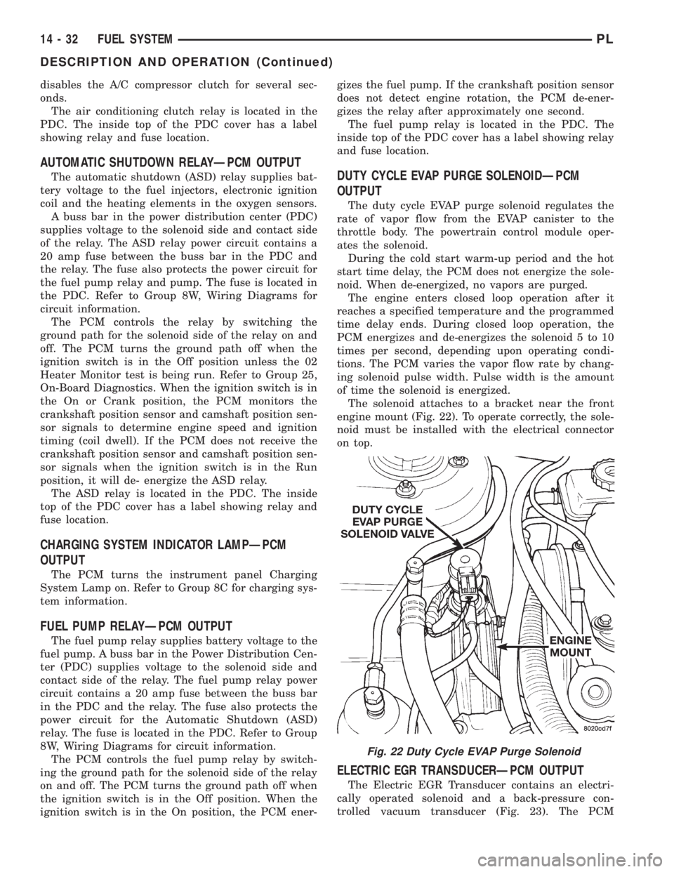
The solenoid attaches to a bracket near the front
engine mount (Fig. 22). To operate correctly, the sole-
noid must be installed with the electrical connector
on top.
ELECTRIC EGR TRANSDUCERÐPCM OUTPUT
The Electric EGR Transducer contains an electri-
cally operated solenoid and a back-pressure con-
trolled vacuum transducer (Fig. 23). The PCM
Fig. 22 Duty Cycle EVAP Purge Solenoid
14 - 32 FUEL SYSTEMPL
DESCRIPTION AND OPERATION (Continued)