1999 DODGE NEON turn signal
[x] Cancel search: turn signalPage 89 of 1200

either through the park brake switch, the fluid level
sensor in the master cylinder reservoir, or the igni-
tion switch in the crank position.
The Brake Fluid Level sensor is located in the
brake fluid reservoir of the master cylinder assembly
(Fig. 18). The purpose of the sensor is to provide the
driver with an early warning that the brake fluid
level in the master cylinder reservoir has dropped to
below normal. This may indicate an abnormal loss of
brake fluid in the master cylinder fluid reservoir
resulting from a leak in the hydraulic system.
As the fluid drops below the minimum level, the
fluid level sensor closes the brake warning light cir-
cuit. This will turn on the red brake warning light.
At this time, master cylinder fluid reservoir shouldbe checked and filled to the full mark with DOT 3
brake fluid.If brake fluid level has dropped in
master cylinder fluid reservoir, the entire
brake hydraulic system should be checked for
evidence of a leak.
STOP LAMP SWITCH
The stop lamp switch controls operation of the
vehicles stop lamps. Also, if the vehicle is equipped
with speed control, the stop lamp switch will deacti-
vate speed control when the brake pedal is
depressed.
The stop lamp switch controls operation of the
right and left tail, stop and turn signal lamp and
CHMSL lamp, by supplying battery current to these
lamps.
The stop lamp switch controls the lamp operation
by opening and closing the electrical circuit to the
stop lamps.
REAR WHEEL HUB/BEARING
CAUTION: If a vehicle is equipped with antilock
brakes the tone wheels for the rear wheel speed
sensors are pressed onto the hub. The tone wheels
used on this vehicle equipped with the Teves Mark
20 Antilock Brake System are different then those
used on past models of this vehicle equipped with
antilock brakes. Reduced braking performance will
result if this part is used on earlier model vehicles
and an accident could result. Do not use on
pre-1998 model year vehicles.
All vehicles are equipped with permanently lubri-
cated and sealed for life rear wheel bearings. There
is no periodic lubrication or maintenance recom-
mended for these units. However, if servicing of a
rear wheel bearing is required, refer to procedures in
the diagnosis and testing section and the removal
and installation section in this group of the service
manual for the inspection and replacement of the
rear wheel bearing.Fig. 17 Power Brake Booster Assembly
Fig. 18 Master Cylinder Fluid Level Sensor
5 - 8 BRAKESPL
DESCRIPTION AND OPERATION (Continued)
Page 151 of 1200
This is accomplished by a sophisticated system of
electrical and hydraulic components. As a result,
there are a few performance characteristics that may
at first seem different but should be considered nor-
mal. These characteristics are discussed below.
NORMAL BRAKING SYSTEM FUNCTION
Under normal braking conditions, the ABS System
functions the same as a standard brake system with
a diagonally split master cylinder and conventional
vacuum assist.
ABS SYSTEM OPERATION
If a wheel locking tendency is detected during a
brake application, the brake system will enter the
ABS mode. During ABS braking, hydraulic pressure
in the four wheel circuits is modulated to prevent
any wheel from locking. Each wheel circuit is
designed with a set of electric solenoids to allow mod-
ulation, although for vehicle stability, both rear
wheel solenoids receive the same electrical signal.
During an ABS stop, the brakes hydraulic system
is still diagonally split. However, the brake system
pressure is further split into four control channels.
During antilock operation of the vehicle's brake sys-
tem the front wheels are controlled independently
and are on two separate control channels and the
rear wheels of the vehicle are controlled together.
The system can build and release pressure at each
wheel, depending on signals generated by the wheel
speed sensors (WSS) at each wheel and received at
the Controller Antilock Brake (CAB).
ABS operation is available at all vehicle speeds
above 3 to 5 mph. Wheel lockup may be perceived at
the very end of an ABS stop and is considered nor-
mal.
VEHICLE HANDLING PERFORMANCE DURING
ABS BRAKING
It is important to remember that an antilock brake
system does not shorten a vehicle's stopping distance
under all driving conditions, but does provide
improved control of the vehicle while stopping. Vehi-
cle stopping distance is still dependent on vehicle
speed, weight, tires, road surfaces and other factors.
Though ABS provides the driver with some steer-
ing control during hard braking, there are conditions
however, where the system does not provide any ben-
efit. In particular, hydroplaning is still possible when
the tires ride on a film of water. This results in the
vehicles tires leaving the road surface rendering the
vehicle virtually uncontrollable. In addition, extreme
steering maneuvers at high speed or high speed cor-
nering beyond the limits of tire adhesion to the road
surface may cause vehicle skidding, independent of
vehicle braking. For this reason, the ABS system is
termed Antilock instead of Anti-Skid.
NOISE AND BRAKE PEDAL FEEL
During ABS braking, some brake pedal movement
may be felt. In addition, ABS braking will create
ticking, popping and/or groaning noises heard by the
driver. This is normal due to pressurized fluid being
transferred between the master cylinder and the
brakes. If ABS operation occurs during hard braking,
some pulsation may be felt in the vehicle body due to
fore and aft movement of the suspension as brake
pressures are modulated.
At the end of an ABS stop, ABS will be turned off
when the vehicle is slowed to a speed of 3±4 mph.
There may be a slight brake pedal drop anytime that
the ABS is deactivated, such as at the end of the stop
when the vehicle speed is less then 3 mph or during
an ABS stop where ABS is no longer required. These
conditions will exist when a vehicle is being stopped
on a road surface with patches of ice, loose gravel or
sand on it. Also stopping a vehicle on a bumpy road
surface will activate ABS because of the wheel hop
caused by the bumps.
TIRE NOISE AND MARKS
Although the ABS system prevents complete wheel
lock-up, some wheel slip is desired in order to
achieve optimum braking performance. Wheel slip is
defined as follows, 0 percent slip means the wheel is
rolling freely and 100 percent slip means the wheel is
fully locked. During brake pressure modulation,
wheel slip is allowed to reach up to 25 to30%. This
means that the wheel rolling velocity is 25 to 30%
less than that of a free rolling wheel at a given vehi-
cle speed. This slip may result in some tire chirping,
depending on the road surface. This sound should not
be interpreted as total wheel lock-up.
Complete wheel lock up normally leaves black tire
marks on dry pavement. The ABS System will not
leave dark black tire marks since the wheel never
reaches a fully locked condition. Tire marks may
however be noticeable as light patched marks.
START UP CYCLE
When the ignition is turned on, a popping sound
and a slight brake pedal movement may be noticed.
Additionally, when the vehicle is first driven off a
humming may be heard and/or felt by the driver at
approximately 20 to 40 kph (12 to 25 mph). The ABS
warning lamp will also be on for up to 5 seconds
after the ignition is turned on. All of these conditions
are a normal function of ABS as the system is per-
forming a diagnosis check.
5 - 70 BRAKESPL
DESCRIPTION AND OPERATION (Continued)
Page 155 of 1200
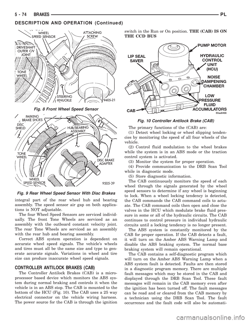
integral part of the rear wheel hub and bearing
assembly. The speed sensor air gap on both applica-
tions is NOT adjustable.
The four Wheel Speed Sensors are serviced individ-
ually. The front Tone Wheels are serviced as an
assembly with the outboard constant velocity joint.
The rear Tone Wheels are serviced as an assembly
with the rear hub and bearing assembly.
Correct ABS system operation is dependent on
accurate wheel speed signals. The vehicle's wheels
and tires must all be the same size and type to gen-
erate accurate signals. Variations in wheel and tire
size can produce inaccurate wheel speed signals.
CONTROLLER ANTILOCK BRAKES (CAB)
The Controller Antilock Brakes (CAB) is a micro-
processor based device which monitors the ABS sys-
tem during normal braking and controls it when the
vehicle is in an ABS stop. The CAB is mounted to the
bottom of the HCU (Fig. 10). The CAB uses a 25 way
electrical connector on the vehicle wiring harness.
The power source for the CAB is through the ignitionswitch in the Run or On position.THE (CAB) IS ON
THE CCD BUS
The primary functions of the (CAB) are:
(1) Detect wheel locking or wheel slipping tenden-
cies by monitoring the speed of all four wheels of the
vehicle.
(2) Control fluid modulation to the wheel brakes
while the system is in an ABS mode or the traction
control system is activated.
(3) Monitor the system for proper operation.
(4) Provide communication to the DRB Scan Tool
while in diagnostic mode.
(5) Store diagnostic information.
The CAB continuously monitors the speed of each
wheel through the signals generated by the wheel
speed sensors to determine if any wheel is beginning
to lock. When a wheel locking tendency is detected,
the CAB commands the CAB command coils to actu-
ate. The CAB command coils then open and close the
valves in the HCU which modulate brake fluid pres-
sure in some or all of the hydraulic circuits. The CAB
continues to control pressure in individual hydraulic
circuits until a locking tendency is no longer present.
The ABS system is constantly monitored by the
CAB for proper operation. If the CAB detects a fault,
it will turn on the Amber ABS Warning Lamp and
disable the ABS braking system. The normal base
braking system will remain operational.
The CAB contains a self-diagnostic program which
will turn on the Amber ABS Warning Lamp when a
ABS system fault is detected. Faults are then stored
in a diagnostic program memory. There are multiple
fault messages which may be stored in the CAB and
displayed through the DRB Scan Tool. These fault
messages will remain in the CAB memory even after
the ignition has been turned off. The fault messages
can be read and or cleared from the CAB memory by
a technician using the DRB Scan Tool. The fault
occurrence and the fault code will also be automati-
Fig. 8 Front Wheel Speed Sensor
Fig. 9 Rear Wheel Speed Sensor With Disc Brakes
Fig. 10 Controller Antilock Brake (CAB)
5 - 74 BRAKESPL
DESCRIPTION AND OPERATION (Continued)
Page 160 of 1200
A visual inspection for loose, disconnected, or mis-
routed wires should be done before attempting to
diagnose or service the ITT Teves Mark 20 antilock
brake system. A visual inspection will eliminate
unnecessary testing and diagnostics time. A thorough
visual inspection will include the following compo-
nents and areas of the vehicle.
(1) Inspect fuses in the power distribution center
(PDC) and the wiring junction block. Verify that all
fuses are fully inserted into the PDC and wring junc-
tion block. A label on the underside of the PDC cover
identifies the locations of the ABS fuses in the PDC.
(2) Inspect the 25-way electrical connector at the
CAB for damage, spread or backed-out wiring termi-
nals. Verify that the 25-way connector is fully
inserted in the socket on the CAB. Be sure that wires
are not stretched tight or pulled out of the connector.
(3) Verify that all the wheel speed sensor connec-
tions are secure.
(4) Poor mating of connector halves or terminals
not fully seated in the connector body.
(5) Improperly formed or damaged terminals. All
connector terminals in a suspect circuit should be
carefully reformed to increase contact tension.
(6) Poor terminal to wire connection. This requires
removing the terminal from the connector body to
inspect.
(7) Pin presence in the connector assembly
(8) Proper ground connections. Check all ground
connections for signs of corrosion, tight fasteners, or
other potential defects. Refer to wiring diagram man-
ual for ground locations.
(9) Problems with main power sources of the vehi-
cle. Inspect battery, generator, ignition circuits and
other related relays and fuses.
(10) If a visual check does not find the cause of the
problem, operate the car in an attempt to duplicate
the condition and record the trouble code.
(11) Most failures of the ABS system will disable
ABS function for the entire ignition cycle even if the
fault clears before key-off. There are some failure
conditions, however, which will allow ABS operation
to resume during the ignition cycle in which a failure
occurred if the failure conditions are no longer
present. The following conditions may result in inter-
mittent illumination of the ABS Warning Lamp. All
other failures will cause the lamp to remain on until
the ignition switch is turned off. Circuits involving
these inputs to the CAB should be investigated if a
complaint of intermittent warning system operation
is encountered.
(12) Low system voltage. If Low System Voltage is
detected by the CAB, the CAB will turn on the ABS
Warning Lamp until normal system voltage is
achieved. Once normal voltage is seen at the CAB,
normal operation resumes.(13) High system voltage. If high system voltage is
detected by the CAB, the CAB will turn on the
Amber ABS Warning Lamp until normal system volt-
age is achieved. Once normal voltage is again
detected by the CAB, normal ABS operation resumes.
(14) Additionally, any condition which results in
interruption of electrical current to the CAB or mod-
ulator assembly may cause the ABS Warning Lamp
to turn on intermittently.
(15) The body controller can turn on the (yellow)
ABS warning lamp if CCD communication between
the body controller and the CAB is interupted.
TONEWHEEL INSPECTION
CAUTION: The tone wheels used on this vehicle
equipped with the Teves Mark 20 Antilock Brake
System are different then those used on past mod-
els of this vehicle equipped with antilock brakes.
Reduced braking performance will result if this part
is used on earlier model vehicles and an accident
could result. Do not use on pre-1998 model year
vehicles.
Carefully inspect tonewheel at the suspected faulty
wheel speed sensor for missing, chipped or broken
teeth, this can cause erratic speed sensor signals.
Tonewheels should show no evidence of contact
with the wheel speed sensors. If contact was made,
determine cause and correct before replacing the
wheel speed sensor.
Excessive runout of the tonewheel can cause
erratic wheel speed sensor signals. Refer to Tone-
wheel Runout in the Specification Section in this sec-
tion of the service manual for the tonewheel runout
specification. Replace drive shaft assembly or rear
hub/bearing assembly if tonewheel runout exceeds
the specification.
Inspect tonewheels for looseness on their mounting
surfaces. Tonewheels are pressed onto their mounting
surfaces and should not rotate independently from
the mounting surface.
Check the wheel speed sensor head alignment to
the tone wheel. Also check the gap between the speed
sensor head and the tone wheel to ensure it is at
specification. Refer to Wheel Speed Sensor Clearance
in the Specification Section in this section of the ser-
vice manual.
PROPORTIONING VALVE
CAUTION: Proportioning valves should never be
disassembled.
If premature rear wheel skid occurs on a hard
brake application, it could be an indication that a
PLBRAKES 5 - 79
DIAGNOSIS AND TESTING (Continued)
Page 252 of 1200

Plastic clips in various locations protect the cables
from damage. When the cables are replaced the clips
must be used to prevent damage to the cables. The
#1 cable must be routed under the PCV hose and
clipped to the #2 cable.
ELECTRONIC IGNITION COILS
WARNING: THE DIRECT IGNITION SYSTEM GEN-
ERATES APPROXIMATELY 40,000 VOLTS. PER-
SONAL INJURY COULD RESULT FROM CONTACT
WITH THIS SYSTEM.
The coil pack consists of 2 coils molded together.
The coil pack is mounted on the valve cover (Fig. 3)
or (Fig. 4). High tension leads route to each cylinder
from the coil. The coil fires two spark plugs every
power stroke. One plug is the cylinder under com-
pression, the other cylinder fires on the exhaust
stroke. Coil number one fires cylinders 1 and 4. Coil
number two fires cylinders 2 and 3. The PCM deter-
mines which of the coils to charge and fire at the cor-
rect time.
The Auto Shutdown (ASD) relay provides battery
voltage to the ignition coil. The PCM provides a
ground contact (circuit) for energizing the coil. When
the PCM breaks the contact, the energy in the coil
primary transfers to the secondary causing the
spark. The PCM will de-energize the ASD relay if it
does not receive the crankshaft position sensor and
camshaft position sensor inputs. Refer to Auto Shut-
down (ASD) RelayÐPCM Output, in this section for
relay operation.
AUTOMATIC SHUTDOWN RELAY
The Automatic Shutdown (ASD) relay supplies bat-
tery voltage to the fuel injectors, electronic ignition
coil and the heating elements in the oxygen sensors.
A buss bar in the Power Distribution Center (PDC)
supplies voltage to the solenoid side and contact sideof the relay. The ASD relay power circuit contains a
20 amp fuse between the buss bar in the PDC and
the relay. The fuse also protects the power circuit for
the fuel pump relay and pump. The fuse is located in
the PDC. Refer to Group 8W, Wiring Diagrams for
circuit information.
The PCM controls the ASD relay by switching the
ground path for the solenoid side of the relay on and
off. The PCM turns the ground path off when the
ignition switch is in the Off position. When the igni-
tion switch is in On or Start, the PCM monitors the
crankshaft and camshaft position sensor signals to
determine engine speed and ignition timing (coil
dwell). If the PCM does not receive crankshaft and
camshaft position sensor signals when the ignition
switch is in the Run position, it will de-energize the
ASD relay.
The ASD relay is located in the PDC (Fig. 5). The
inside top of the PDC cover has label showing relay
and fuse identification.
Fig. 3 Ignition Coil PackÐSOHC
Fig. 4 Ignition Coil PackÐDOHC
Fig. 5 Power Distribution Center (PDC)
PLIGNITION SYSTEM 8D - 3
DESCRIPTION AND OPERATION (Continued)
Page 258 of 1200

ply circuit shorts to ground, neither sensor will pro-
duce a signal (output voltage to the PCM).
When the ignition key is turned and left in the On
position, the PCM automatically energizes the Auto
Shutdown (ASD) relay. However, the controller de-en-
ergizes the relay within one second because it has
not received a camshaft position sensor signal indi-
cating engine rotation.
During cranking, the ASD relay will not energize
until the PCM receives a camshaft position sensor
signal. Secondly, the ASD relay remains energized
only if the controller senses a crankshaft position
sensor signal immediately after detecting the cam-
shaft position sensor signal.
(1) Check battery voltage. Voltage should approxi-
mately 12.66 volts or higher to perform failure to
start test.
(2) Disconnect the harness connector from the coil
pack (Fig. 20).
(3) Connect a test light to the B+ (battery voltage)
terminal of the coil electrical connector and ground.
The B+ wire for the DIS coil is the center terminal.
Do not spread the terminal with the test light
probe.
(4) Turn the ignition key to theON position.The
test light should flash On and then Off.Do not turn
the Key to off position, leave it in the On posi-
tion.
(a) If the test light flashes momentarily, the
PCM grounded the ASD relay. Proceed to step 5.
(b) If the test light did not flash, the ASD relay
did not energize. The cause is either the relay or
one of the relay circuits. Use the DRB scan tool to
test the ASD relay and circuits. Refer to the appro-
priate Powertrain Diagnostics Procedure Manual.
Refer to the wiring diagrams section for circuit
information.
(5) Crank the engine. (If the key was placed in the
off position after step 4, place the key in the On posi-tion before cranking. Wait for the test light to flash
once, then crank the engine.)
(6) If the test light momentarily flashes during
cranking, the PCM is not receiving a crankshaft posi-
tion sensor signal.
(7) If the test light did not flash during cranking,
unplug the crankshaft position sensor connector.
Turn the ignition key to the off position. Turn the
key to the On position, wait for the test light to
momentarily flash once, then crank the engine. If the
test light momentarily flashes, the crankshaft posi-
tion sensor is shorted and must be replaced. If the
light did not flash, the cause of the no-start is in
either the crankshaft position sensor/camshaft posi-
tion sensor 8 volt supply circuit, or the camshaft
position sensor output or ground circuits.
IGNITION TIMING PROCEDURE
The engines for this vehicle, use a fixed ignition
system. The PCM regulates ignition timing. Basic
ignition timing is not adjustable.
CAMSHAFT POSITION SENSOR AND CRANKSHAFT
POSITION SENSOR
The output voltage of a properly operating cam-
shaft position sensor or crankshaft position sensor
switches from high (5.0 volts) to low (0.3 volts). By
connecting an Moper Diagonostic System (MDS) and
engine analyzer to the vehicle, technicians can view
the square wave pattern.
ENGINE COOLANT TEMPERATURE SENSOR
Refer to Group 14, Fuel System for Diagnosis and
Testing.
INTAKE AIR TEMPERATURE SENSOR
Refer to Group 14, Fuel System, for Diagnosis and
Testing.
MANIFOLD ABSOLUTE PRESSURE (MAP) SENSOR
TEST
Refer to Group 14, Fuel System for Diagnosis and
Testing.
THROTTLE POSITION SENSOR
To perform a complete test of the this sensor and
its circuitry, refer to the DRB scan tool and appropri-
ate Powertrain Diagnostics Procedures manual. To
test the throttle position sensor only, refer to the fol-
lowing:
The Throttle Position Sensor (TPS) can be tested
with a digital voltmeter (DVM). The center terminal
of the sensor is the output terminal. One of the other
terminals is a 5 volt supply and the remaining ter-
minal is ground.
Fig. 20 Ignition Coil Engine Harness Connector
PLIGNITION SYSTEM 8D - 9
DIAGNOSIS AND TESTING (Continued)
Page 271 of 1200
When the ignition switch is in the OFF position, or
when the radio frequency is being displayed, time
keeping is accurately maintained.
The procedure for setting the clock varies slightly
with each radio. The correct procedure is described in
the individual radio operating instructions. Refer to
the Owner's Manual supplied with the vehicle.
INSTRUMENT CLUSTER
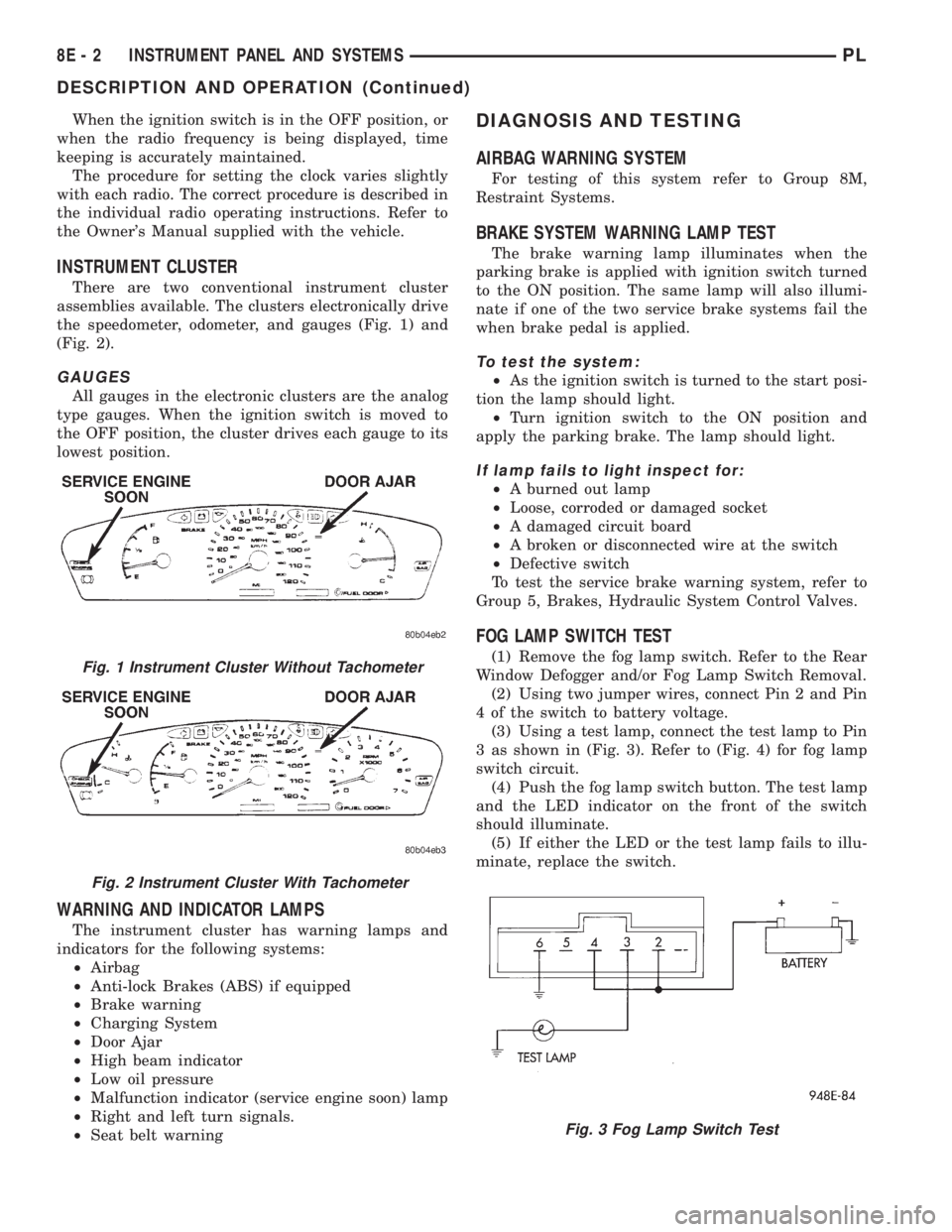
There are two conventional instrument cluster
assemblies available. The clusters electronically drive
the speedometer, odometer, and gauges (Fig. 1) and
(Fig. 2).
GAUGES
All gauges in the electronic clusters are the analog
type gauges. When the ignition switch is moved to
the OFF position, the cluster drives each gauge to its
lowest position.
WARNING AND INDICATOR LAMPS
The instrument cluster has warning lamps and
indicators for the following systems:
²Airbag
²Anti-lock Brakes (ABS) if equipped
²Brake warning
²Charging System
²Door Ajar
²High beam indicator
²Low oil pressure
²Malfunction indicator (service engine soon) lamp
²Right and left turn signals.
²Seat belt warning
DIAGNOSIS AND TESTING
AIRBAG WARNING SYSTEM
For testing of this system refer to Group 8M,
Restraint Systems.
BRAKE SYSTEM WARNING LAMP TEST
The brake warning lamp illuminates when the
parking brake is applied with ignition switch turned
to the ON position. The same lamp will also illumi-
nate if one of the two service brake systems fail the
when brake pedal is applied.
To test the system:
²As the ignition switch is turned to the start posi-
tion the lamp should light.
²Turn ignition switch to the ON position and
apply the parking brake. The lamp should light.
If lamp fails to light inspect for:
²A burned out lamp
²Loose, corroded or damaged socket
²A damaged circuit board
²A broken or disconnected wire at the switch
²Defective switch
To test the service brake warning system, refer to
Group 5, Brakes, Hydraulic System Control Valves.
FOG LAMP SWITCH TEST
(1) Remove the fog lamp switch. Refer to the Rear
Window Defogger and/or Fog Lamp Switch Removal.
(2) Using two jumper wires, connect Pin 2 and Pin
4 of the switch to battery voltage.
(3) Using a test lamp, connect the test lamp to Pin
3 as shown in (Fig. 3). Refer to (Fig. 4) for fog lamp
switch circuit.
(4) Push the fog lamp switch button. The test lamp
and the LED indicator on the front of the switch
should illuminate.
(5) If either the LED or the test lamp fails to illu-
minate, replace the switch.Fig. 1 Instrument Cluster Without Tachometer
Fig. 2 Instrument Cluster With Tachometer
Fig. 3 Fog Lamp Switch Test
8E - 2 INSTRUMENT PANEL AND SYSTEMSPL
DESCRIPTION AND OPERATION (Continued)
Page 274 of 1200
(2) Turn the ignition switch to the ON position.
The fuel gauge should be at its lowest position. Turn
the ignition switch OFF.
(3) Ground fuel gauge sending unit connector Pin
3. Refer to Group 8W, Wiring Diagrams. Turn igni-
tion switch to the ON position. The fuel gauge should
be at its highest position. Turn ignition switch OFF
then ON, after a sending unit signal change to dis-
able the cluster electronic gauge dampening mecha-
nism.
(a) If OK, check the fuel gauge sending unit con-
nector for proper connection. If the connections are
OK, refer to Group 14 Fuel System for Fuel Level
Sensor Diagnosis.
(b) If not OK, connect the sending unit. Remove
the cluster and check for an open or short in the
sending unit wiring. The sending unit will be less
than 1080 ohms and greater than 50 ohms depend-
ing upon fuel level. If the sending unit wiring is
open or a short circuit, repair as necessary.
(c) If the sending unit wiring is OK, replace the
gauge assembly. If the condition persists, replace
the cluster printed circuit board.
FUEL GAUGE INCORRECTLY INDICATES
EMPTY
The fuel system uses both the instrument cluster
and the Powertrain Control Module (PCM) to moni-
tor the fuel level sending unit. If the PCM fuel mon-
itoring circuits senses an open circuit, the increased
circuit resistance will causes a false fuel gauge empty
reading. Check for continuity between cluster wire
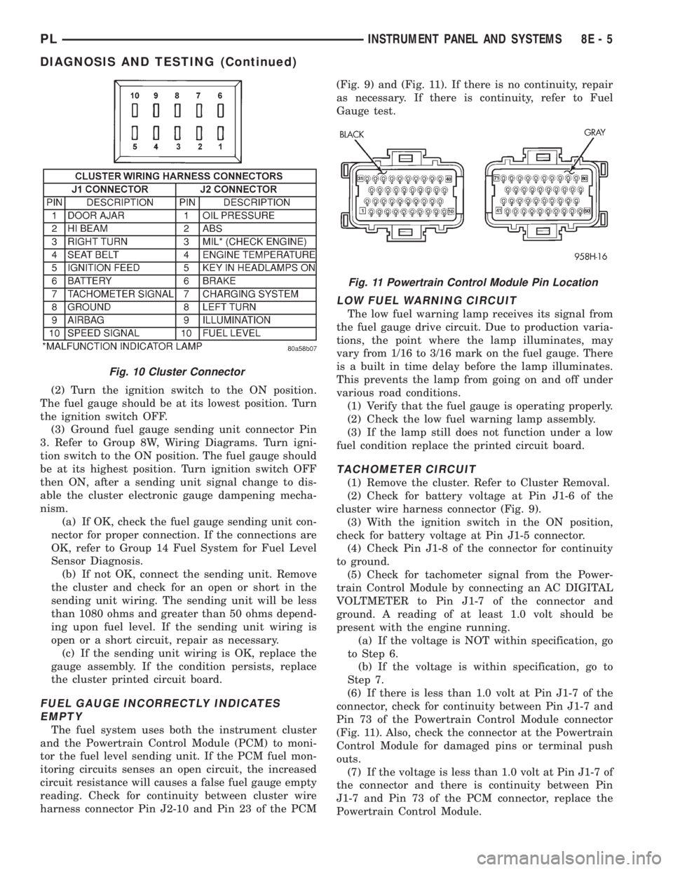
harness connector Pin J2-10 and Pin 23 of the PCM(Fig. 9) and (Fig. 11). If there is no continuity, repair
as necessary. If there is continuity, refer to Fuel
Gauge test.
LOW FUEL WARNING CIRCUIT
The low fuel warning lamp receives its signal from
the fuel gauge drive circuit. Due to production varia-
tions, the point where the lamp illuminates, may
vary from 1/16 to 3/16 mark on the fuel gauge. There
is a built in time delay before the lamp illuminates.
This prevents the lamp from going on and off under
various road conditions.
(1) Verify that the fuel gauge is operating properly.
(2) Check the low fuel warning lamp assembly.
(3) If the lamp still does not function under a low
fuel condition replace the printed circuit board.
TACHOMETER CIRCUIT
(1) Remove the cluster. Refer to Cluster Removal.
(2) Check for battery voltage at Pin J1-6 of the
cluster wire harness connector (Fig. 9).
(3) With the ignition switch in the ON position,
check for battery voltage at Pin J1-5 connector.
(4) Check Pin J1-8 of the connector for continuity
to ground.
(5) Check for tachometer signal from the Power-
train Control Module by connecting an AC DIGITAL
VOLTMETER to Pin J1-7 of the connector and
ground. A reading of at least 1.0 volt should be
present with the engine running.
(a) If the voltage is NOT within specification, go
to Step 6.
(b) If the voltage is within specification, go to
Step 7.
(6) If there is less than 1.0 volt at Pin J1-7 of the
connector, check for continuity between Pin J1-7 and
Pin 73 of the Powertrain Control Module connector
(Fig. 11). Also, check the connector at the Powertrain
Control Module for damaged pins or terminal push
outs.
(7) If the voltage is less than 1.0 volt at Pin J1-7 of
the connector and there is continuity between Pin
J1-7 and Pin 73 of the PCM connector, replace the
Powertrain Control Module.
Fig. 10 Cluster Connector
Fig. 11 Powertrain Control Module Pin Location
PLINSTRUMENT PANEL AND SYSTEMS 8E - 5
DIAGNOSIS AND TESTING (Continued)