Page 1420 of 3115

- DIAGNOSTICSENGINE
DI-17
210 Author�: Date�:
8. ACTIVE TEST
HINT:
Performing the ACTIVE TEST using the hand-held tester or the OBD II scan tool allows the relay, VSV, ac-
tuator and so on to operate without parts removal. Performing the ACTIVE TEST as a first step of trouble-
shooting is one method to shorten diagnostic time.
It is possible to display the DATA LIST during the ACTIVE TEST.
(a) Warm up the engine.
(b) Turn the ignition switch OFF.
(c) Connect the hand-held tester or the OBD II scan tool to the DLC3.
(d) Turn the ignition switch ON.
(e) Push the ºONº button of the hand-held tester or the OBD II scan tool.
(f) Enter the following menus: DIAGNOSIS / ENHANCED OBD II / ACTIVE TEST.
(g) According to the display on tester, perform the ºACTIVE TESTº.
ItemTest DetailsDiagnostic Note
INJ VOL
[Test Details]
Control the injection volume.
Min.: -12.5%, Max.: 24.8%
[Vehicle Condition]
Engine speed: 3,000 rpm or less.�All injectors are tested at
once.
�Injection volume is gradual-
ly changed between -12.5
and 25%
A/F CONTROL
[Test Details]
Control injection volume
-12.5 or 25 % (change injection volume -12.5 % or 25 %)
[Vehicle Condition]
Engine speed: 3,000 rpm or less
Following A/F CONTROL
procedure enables techni-
cian to check and graph volt-
age outputs of both the A/F
sensor and heated oxygen
sensor
For displaying graph, enter
ºACTIVE TEST / A/F CON-
TROL / USER DATAº, select
ºAFS B1S1 and O2S B1S2º
by pressing ºYESº and push
ºENTERº. Then press ºF4º
FUEL PUMP / SPD
[Test Details]
Control the fuel pump speed.
ON or OFF
-
VVT CTRL B1
[Test Details]
Active VVT system (Bank 1)
ON or OFF�ON: Rough idle or engine
stall
�OFF: Normal engine speed
VVT CTRL B2
[Test Details]
Active VVT system (Bank 2)
ON or OFF�ON: Rough idle or engine
stall
�OFF: Normal engine speed
CAN CTRL VSV
[Test Details]
Activate the VSV for canister control.
ON or OFF
-
TANK BYPASS VSV
[Test Details]
Activate the VSV for tank bypass.
ON or OFF
-
A/C MAG CLUTCH
[Test Details]
Control the A/C magnet clutch.
ON or OFF
-
EVAP VSV (ALONE)
[Test Details]
Activate the VSV for EVAP control.
ON or OFF
-
Page 1872 of 3115
A21821
Oil Cooler Pipe
for Transmission
Transmission (w/ Torque
Converter Clutch)
Engine
Front Spacer
Flywheel Housing Under CoverRear Spacer
Drive Plate x 10
37 (380, 27) for 14 mm Head
72 (730, 53) for 17 mm Head
48 (490, 35)
x 8
x 6
N´m (kgf´cm, ft´lbf) : Specified torque
� Non-reusable part
� Precoated part� �
Clamp
Connector
Connector
Stay
StayStay
See page EM-81
1st 49 (500, 36)
2nd Turn 90°
EM-76
- ENGINE MECHANICALENGINE UNIT
1649 Author�: Date�:
2004 LAND CRUISER (RM1071U)
Page 1873 of 3115

EM0LA-07
A04869
Adhesive
A04857
1
2
3
4
7
6
8
5
A05137
Painted
Mark
90°
90°
A05119
Ground
Strap
- ENGINE MECHANICALENGINE UNIT
EM-81
1654 Author�: Date�:
2004 LAND CRUISER (RM1071U)
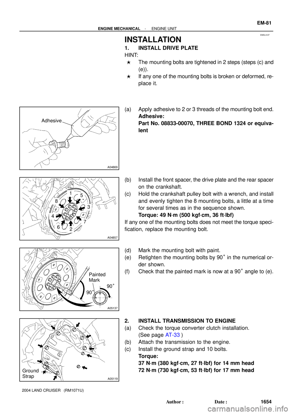
INSTALLATION
1. INSTALL DRIVE PLATE
HINT:
�The mounting bolts are tightened in 2 steps (steps (c) and
(e)).
�If any one of the mounting bolts is broken or deformed, re-
place it.
(a) Apply adhesive to 2 or 3 threads of the mounting bolt end.
Adhesive:
Part No. 08833-00070, THREE BOND 1324 or equiva-
lent
(b) Install the front spacer, the drive plate and the rear spacer
on the crankshaft.
(c) Hold the crankshaft pulley bolt with a wrench, and install
and evenly tighten the 8 mounting bolts, a little at a time
for several times as in the sequence shown.
Torque: 49 N´m (500 kgf´cm, 36 ft´lbf)
If any one of the mounting bolts does not meet the torque speci-
fication, replace the mounting bolt.
(d) Mark the mounting bolt with paint.
(e) Retighten the mounting bolts by 90° in the numerical or-
der shown.
(f) Check that the painted mark is now at a 90° angle to (e).
2. INSTALL TRANSMISSION TO ENGINE
(a) Check the torque converter clutch installation.
(See page AT-33)
(b) Attach the transmission to the engine.
(c) Install the ground strap and 10 bolts.
Torque:
37 N´m (380 kgf´cm, 27 ft´lbf) for 14 mm head
72 N´m (730 kgf´cm, 53 ft´lbf) for 17 mm head
Page 1874 of 3115

P18747
Adhesive
A05084
A07245
A05171
Lower
Up
A05170
EM-82
- ENGINE MECHANICALENGINE UNIT
1655 Author�: Date�:
2004 LAND CRUISER (RM1071U)
3. INSTALL TORQUE CONVERTER CLUTCH BOLTS
(a) Apply adhesive to 2 or 3 threads from the bolt end.
Adhesive:
Part No. 08833-00070, THREE BOND 1324 or equiva-
lent
(b) Hold the crankshaft pulley bolt with a wrench, and install
the 6 bolts evenly.
Torque: 48 N´m (490 kgf´cm, 35 ft´lbf)
HINT:
First install the black colored bolt, install the other bolts.
(c) Install the flywheel housing under cover with the bolt.
Torque: 18 N´m (185 kgf´cm, 13 ft´lbf)
4. INSTALL OIL COOLER PIPE FOR TRANSMISSION
5. CONNECT ENGINE WIRE TO TRANSMISSION
(a) Connect the 5 connectors.
(b) Connect the 2 wire clamps.
6. INSTALL ENGINE AND TRANSMISSION ASSEMBLY
IN VEHICLE
(a) Attach the engine chain hoist to the engine hangers.
(b) Slowly lower the engine and the transmission assembly
into the engine compartment.
(c) Attach the engine mounting brackets to the frame brack-
ets.
(d) Keep the engine level with a jack.
Page 1881 of 3115
A07245
A05084
A05119
A04857
EM-80
- ENGINE MECHANICALENGINE UNIT
1653 Author�: Date�:
2004 LAND CRUISER (RM1071U)
22. REMOVE TORQUE CONVERTER CLUTCH BOLTS
(a) Remove the bolt and the flywheel housing under cover.
(b) Turn the crankshaft pulley bolt to gain access to each bolt.
(c) Hold the crankshaft pulley bolt with a wrench, and remove
the 6 bolts.
23. REMOVE TRANSMISSION
(a) Remove the 10 bolts.
(b) Remove the transmission together with the torque con-
verter clutch from the engine.
24. REMOVE DRIVE PLATE
Hold the crankshaft pulley bolt with a wrench, and remove the
8 bolts, the front spacer, the drive plate and the rear spacer.
Page 1918 of 3115

A 1
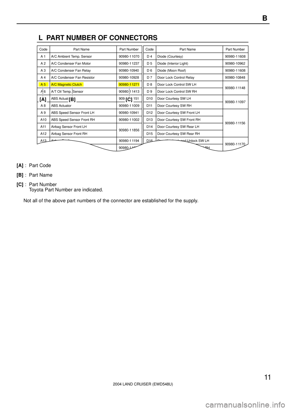
L PART NUMBER OF CONNECTORS
A/C Ambient Temp. Sensor Code
90980-1 1070Part Number
D 4 Diode (Courtesy) Code
90980-1 1608
A 2 A/C Condenser Fan Motor 90980-1 1237 D 5 Diode (Interior Light) 90980-10962
A 3 A/C Condenser Fan Relay 90980-10940 D 6 Diode (Moon Roof) 90980-1 1608
A 4 A/C Condenser Fan Resistor 90980-10928
90980-1 1271D 7 Door Lock Control Relay 90980-10848
A 5 A/C Magnetic Clutch
90980-1 1413D 8 Door Lock Control SW LH
90980-1 1148
A 6 A/T Oil Temp. Sensor
90980-1 1151D 9 Door Lock Control SW RH
A 7 ABS Actuator
90980-1 1009Door Courtesy SW LH
90980-1 1097
A 8 ABS Actuator
90980-10941Door Courtesy SW RH
A 9 ABS Speed Sensor Front LH
90980-1 1002Door Courtesy SW Front LH
ABS Speed Sensor Front RH
90980-1 1856Door Courtesy SW Front RH
90980-1 1156
Airbag Sensor Front LH Door Courtesy SW Rear LH
Airbag Sensor Front RH Door Courtesy SW Rear RH A10
A11
A12
A13 Airbag Squib 90980-1 1194 Door Key Lock and Unlock SW LH
90980-1 1170
90980-1 1070D10
D11
D12
D13
D14
D15
D16
D17 Door Key Lock and Unlock SW RHPart Number Part Name Part Name
[A]
[B] [C]
2004 LAND CRUISER (EWD548U)
11 B
[A]: Part Code
[B]: Part Name
[C]: Part Number
Toyota Part Number are indicated.
Not all of the above part numbers of the connector are established for the supply.
Page 1949 of 3115

2004 LAND CRUISER (EWD548U)
68G ELECTRICAL WIRING ROUTING
Position of Parts in Engine Compartment
A 1 A/C Ambient Temp. Sensor
A 4 Pressure SW
A 5 A/C Lock Sensor
A/C Magnetic Clutch
A 12 ABS Speed Sensor Front LH
A 13 ABS Speed Sensor Front RH
A 15 Airbag Sensor Front LH
A 16 Airbag Sensor Front RH
A 17 Auto Antenna Motor
A 37 ABS & BA & TRAC & VSC Actuator
A 38 ABS & BA & TRAC & VSC Actuator
A 39 ABS & BA & TRAC & VSC Actuator
A 40 ABS & BA & TRAC & VSC Actuator
C 1 Camshaft Position Sensor
C 2 Center Diff. Lock Control Motor
C 3 Crankshaft Position Sensor
D 1 Data Link Connector 1
D 2 Daytime Running Light Relay No.3
D 3 Daytime Running Light Relay No.3
D 4 Detection SW (Center Diff. Lock)
D 5 Detection SW (Transfer L Position)
D 6 Detection SW (Transfer Neutral Position)E 1 Electronically Controlled Transmission Solenoid
E 2 Engine Coolant Temp. Sensor
E 3 Engine Hood Courtesy SW
F 1 Front Fog Light LH
F 2 Front Fog Light RH
F 3 Front Turn Signal Light LH
Side Marker Light LH
F 4 Front Turn Signal Light RH
Side Marker Light RH
F 5 Front Wiper Motor
F 14 Fuel Pump Resistor
F 15 Fusible Link Block
F 16 Fusible Link Block
F 17 Fusible Link Block
F 18 Fusible Link Block
F 19 Fusible Link Block
G 1 Generator
G 2 Generator
Page 1963 of 3115
2004 LAND CRUISER (EWD548U)
380I GROUND POINT
5
Engine
Control
Module E 9
ECE10 5
IH2
IX18E10 E10 Ignition Coil and
Igniter No. 1
Ignition Coil and
Igniter No. 2
Ignition Coil and
Igniter No. 3
Ignition Coil and
Igniter No. 4
Data Link
Connector 3
Combination
SWIgnition Coil and
Igniter No. 5
Ignition Coil and
Igniter No. 6
Ignition Coil and
Igniter No. 7
Ignition Coil and
Igniter No. 8
Center Diff. Lock
Control Motor
Detection SW
(
Transfer Neutral
Position)
EB1
Detection SW
(
Center Diff. Lock)
(
E01)
(
E02)
(
E03)
(
ME01)
Combination
MeterED
IX2 5
E10W- B
W- B
W- B
W- B
W- B
W- B
W- B BR SB BR
BR
SB
W- BBR SB
BR
W- B
W- B
W- B
W- B
W- BW- BW- B
W- B
W- B
W- B
W- B
BR
E10
E10Vehicle Speed
Sensor
(
Combination Meter) BR
BR BR
BR
(
SG)
A/C Magnetic Clutch
A/C Lock SensorEB1 9
W- BIX1 9 3Q53
3E10
W- B
W- B
Noise Filter
(
Ignition) (
ECC)
BR
(
E1)
E10 BR BR
BR
BR