Page 1825 of 3115
A19471
� Gasket
� Gasket20 (200, 14)�
40 (400, 30)�
Heated Oxygen Sensor
(Bank 2 Sensor 1)
RH Front Exhaust Pipe� Gasket
LH Front Exhaust Pipe
Heated Oxygen Sensor
(Bank 1 Sensor 1)
20 (200, 14)�
� Gasket
� Gasket
� Gasket
� Non-reusable part
N´m (kgf´cm, ft´lbf) : Specified torquePS Pump
Oil Dipstick and
Guide for A/T
62 (632, 46)�
40 (400, 30)�
62 (632, 46)
62 (632, 46)�
- ENGINE MECHANICALCYLINDER HEAD
EM-29
1602 Author�: Date�:
2004 LAND CRUISER (RM1071U)
Page 1829 of 3115
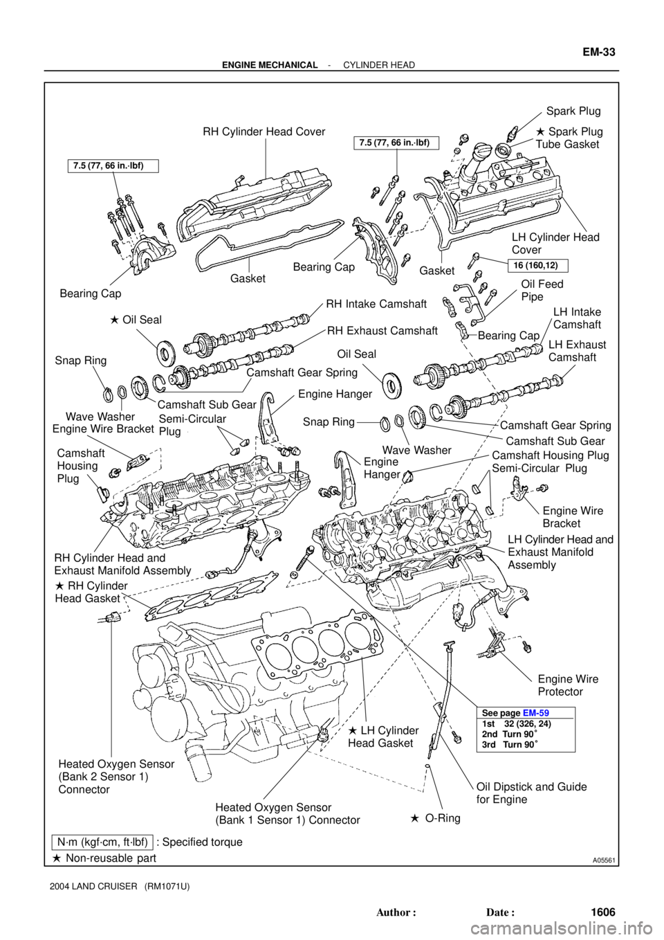
A05561
RH Cylinder Head CoverSpark Plug
LH Cylinder Head
Cover
Gasket
RH Intake Camshaft
RH Exhaust Camshaft Bearing Cap
Bearing CapOil Feed
Pipe
Camshaft Sub Gear Engine Hanger
Heated Oxygen Sensor
(Bank 1 Sensor 1) Connector � RH Cylinder
Head Gasket Engine Wire Bracket
7.5 (77, 66 in.´lbf)
16 (160,12)
Heated Oxygen Sensor
(Bank 2 Sensor 1)
Connector RH Cylinder Head and
Exhaust Manifold AssemblyCamshaft
Housing
Plug Snap Ring
Wave WasherBearing Cap
Oil Seal � Oil Seal
� Non-reusable part
N´m (kgf´cm, ft´lbf) : Specified torque
See page EM-59
1st 32 (326, 24)
2nd Turn 90°
3rd Turn 90°
Semi-Circular
Plug Camshaft Sub GearCamshaft Gear Spring� Spark Plug
Tube Gasket
Gasket
LH Intake
Camshaft
LH Exhaust
Camshaft
Camshaft Gear SpringSnap Ring
Wave Washer
Camshaft Housing Plug
Semi-Circular Plug
Engine Wire
Bracket
Engine
Hanger
� LH Cylinder
Head Gasket
� O-Ring
Oil Dipstick and Guide
for Engine
LH Cylinder Head and
Exhaust Manifold
Assembly
Engine Wire
Protector
7.5 (77, 66 in.´lbf)
- ENGINE MECHANICALCYLINDER HEAD
EM-33
1606 Author�: Date�:
2004 LAND CRUISER (RM1071U)
Page 1850 of 3115
EM7143
Seal Packing
A07250
RH Cylinder Head
LH Cylinder Head
A05509
RH Cylinder Head
LH Cylinder HeadApply Seal Packing
Apply Seal Packing
- ENGINE MECHANICALCYLINDER HEAD
EM-67
1640 Author�: Date�:
2004 LAND CRUISER (RM1071U)
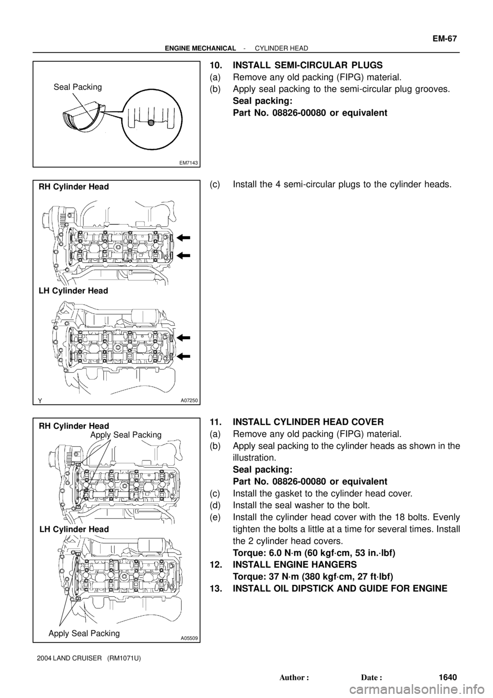
10. INSTALL SEMI-CIRCULAR PLUGS
(a) Remove any old packing (FIPG) material.
(b) Apply seal packing to the semi-circular plug grooves.
Seal packing:
Part No. 08826-00080 or equivalent
(c) Install the 4 semi-circular plugs to the cylinder heads.
11. INSTALL CYLINDER HEAD COVER
(a) Remove any old packing (FIPG) material.
(b) Apply seal packing to the cylinder heads as shown in the
illustration.
Seal packing:
Part No. 08826-00080 or equivalent
(c) Install the gasket to the cylinder head cover.
(d) Install the seal washer to the bolt.
(e) Install the cylinder head cover with the 18 bolts. Evenly
tighten the bolts a little at a time for several times. Install
the 2 cylinder head covers.
Torque: 6.0 N´m (60 kgf´cm, 53 in.´lbf)
12. INSTALL ENGINE HANGERS
Torque: 37 N´m (380 kgf´cm, 27 ft´lbf)
13. INSTALL OIL DIPSTICK AND GUIDE FOR ENGINE
Page 1853 of 3115
B15320B16469No. 1 Water Bypass Hose
EM-70
- ENGINE MECHANICALCYLINDER HEAD
1643 Author�: Date�:
2004 LAND CRUISER (RM1071U)
(r) Connect the PS air hose to intake manifold.
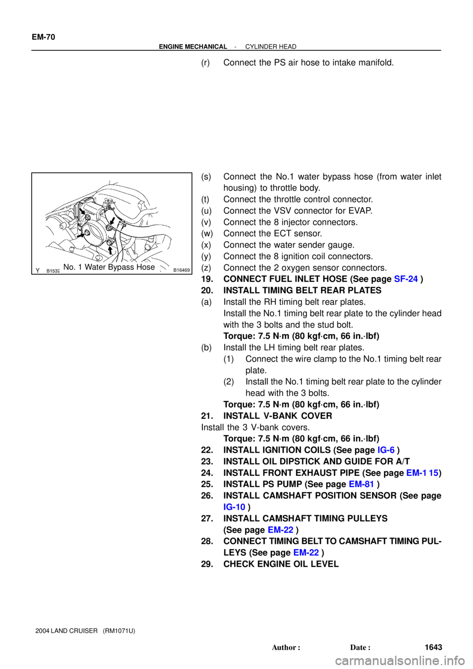
(s) Connect the No.1 water bypass hose (from water inlet
housing) to throttle body.
(t) Connect the throttle control connector.
(u) Connect the VSV connector for EVAP.
(v) Connect the 8 injector connectors.
(w) Connect the ECT sensor.
(x) Connect the water sender gauge.
(y) Connect the 8 ignition coil connectors.
(z) Connect the 2 oxygen sensor connectors.
19. CONNECT FUEL INLET HOSE (See page SF-24)
20. INSTALL TIMING BELT REAR PLATES
(a) Install the RH timing belt rear plates.
Install the No.1 timing belt rear plate to the cylinder head
with the 3 bolts and the stud bolt.
Torque: 7.5 N´m (80 kgf´cm, 66 in.´lbf)
(b) Install the LH timing belt rear plates.
(1) Connect the wire clamp to the No.1 timing belt rear
plate.
(2) Install the No.1 timing belt rear plate to the cylinder
head with the 3 bolts.
Torque: 7.5 N´m (80 kgf´cm, 66 in.´lbf)
21. INSTALL V-BANK COVER
Install the 3 V-bank covers.
Torque: 7.5 N´m (80 kgf´cm, 66 in.´lbf)
22. INSTALL IGNITION COILS (See page IG-6)
23. INSTALL OIL DIPSTICK AND GUIDE FOR A/T
24. INSTALL FRONT EXHAUST PIPE (See page EM-1 15)
25. INSTALL PS PUMP (See page EM-81)
26. INSTALL CAMSHAFT POSITION SENSOR (See page
IG-10)
27. INSTALL CAMSHAFT TIMING PULLEYS
(See page EM-22)
28. CONNECT TIMING BELT TO CAMSHAFT TIMING PUL-
LEYS (See page EM-22)
29. CHECK ENGINE OIL LEVEL
Page 1856 of 3115
EM1V8-01
A02844
- ENGINE MECHANICALCYLINDER HEAD
EM-35
1608 Author�: Date�:
2004 LAND CRUISER (RM1071U)
REMOVAL
1. DRAIN ENGINE COOLANT
2. REMOVE V-BANK COVER
Remove the V-bank covers.
3. DISCONNECT TIMING BELT FROM CAMSHAFT TIM-
ING PULLEYS (See page EM-15)
4. REMOVE CAMSHAFT TIMING PULLEYS (See page
EM-15)
5. REMOVE CAMSHAFT POSITION SENSOR (See page
IG-9)
6. DISCONNECT PS PUMP FROM ENGINE
(See page EM-77)
7. REMOVE FRONT EXHAUST PIPE (See page EM-1 15)
8. REMOVE OIL DIPSTICK AND GUIDE FOR A/T
9. REMOVE IGNITION COILS (See page IG-6)
10. REMOVE TIMING BELT REAR PLATES
(1) Remove the 3 bolts, the stud bolt, and the RH No.1
timing belt rear plates.
(2) Disconnect the wire clamp from the LH timing belt
rear plate.
(3) Remove the 3 bolts, the stud bolt, the LH No.1 and
the timing belt rear plates.
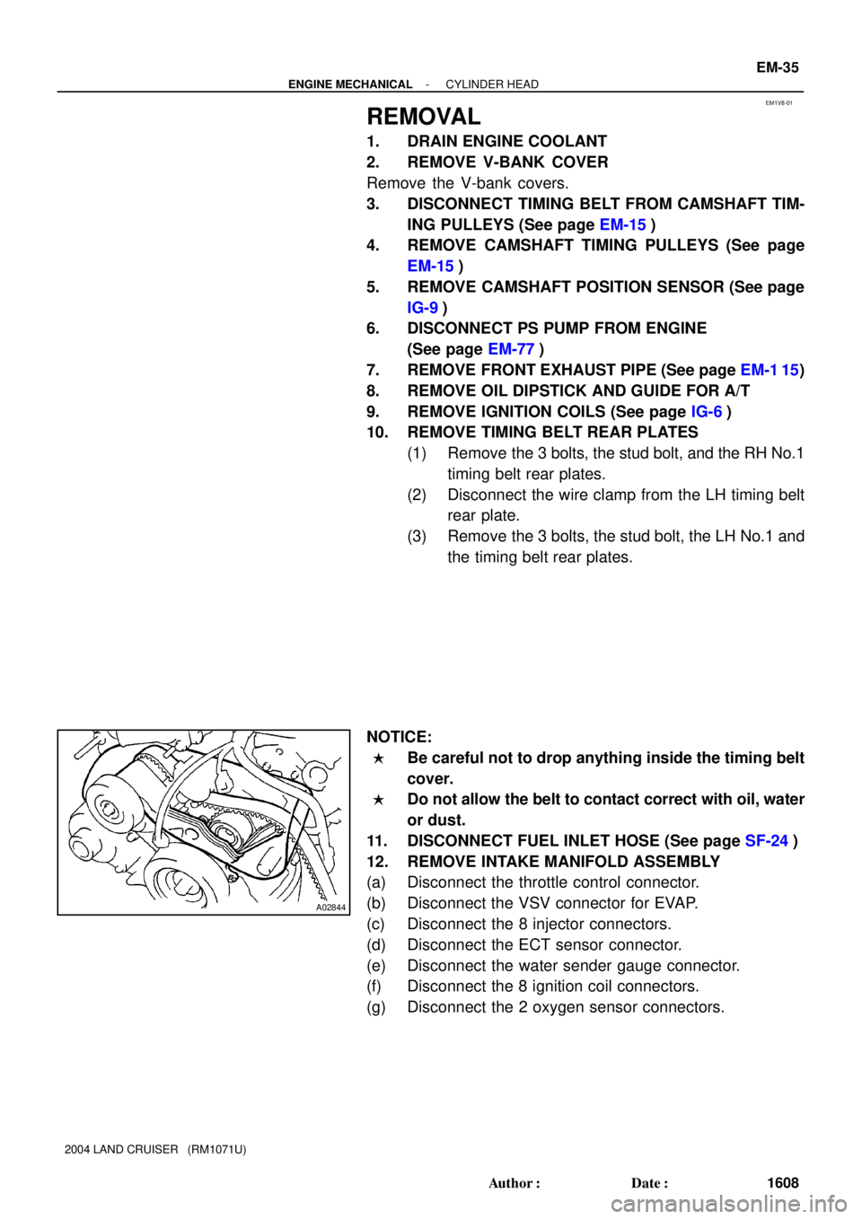
NOTICE:
�Be careful not to drop anything inside the timing belt
cover.
�Do not allow the belt to contact correct with oil, water
or dust.
11. DISCONNECT FUEL INLET HOSE (See page SF-24)
12. REMOVE INTAKE MANIFOLD ASSEMBLY
(a) Disconnect the throttle control connector.
(b) Disconnect the VSV connector for EVAP.
(c) Disconnect the 8 injector connectors.
(d) Disconnect the ECT sensor connector.
(e) Disconnect the water sender gauge connector.
(f) Disconnect the 8 ignition coil connectors.
(g) Disconnect the 2 oxygen sensor connectors.
Page 1859 of 3115
A05516
A05517
A05564
EM-38
- ENGINE MECHANICALCYLINDER HEAD
1611 Author�: Date�:
2004 LAND CRUISER (RM1071U)
14. REMOVE WATER INLET AND INLET HOUSING AS-
SEMBLY (See page CO-6)
15. REMOVE FRONT WATER BYPASS JOINT
Remove the 4 nuts, the water bypass joint and the 2 gaskets.
16. REMOVE REAR WATER BYPASS JOINT
Remove the 4 nuts, the water bypass joint and the 2 gaskets.
17. REMOVE ENGINE HANGERS
18. REMOVE OIL DIPSTICK AND GUIDE FOR A/T
19. REMOVE CYLINDER HEAD COVERS
Remove the 18 bolts, the 18 seal washers, the cylinder head
cover and gasket. Remove the 2 cylinder head covers.
20. IF NECESSARY, REMOVE SEMI-CIRCULAR PLUGS
AND CAMSHAFT HOUSING PLUGS
21. REMOVE CAMSHAFTS
NOTICE:
Since the thrust clearance of the camshaft is small, the
camshaft must be kept level while it is being removed.
Otherwise, excessive pressure is put on the cylinder head
journal thrust, causing a burr on the journal and damage on
the camshaft. To avoid this, follow the steps below.
Page 1902 of 3115
EM0KS-08
A04324
A04325
EM-4
- ENGINE MECHANICALVALVE CLEARANCE
1577 Author�: Date�:
2004 LAND CRUISER (RM1071U)
VALVE CLEARANCE
INSPECTION
HINT:
Inspect and adjust the valve clearance when the engine is cold.
1. DRAIN ENGINE COOLANT
2. REMOVE BATTERY CLAMP COVER
3. REMOVE V-BANK COVER
4. REMOVE AIR CLEANER AND INTAKE AIR CONNEC-
TOR ASSEMBLY
5. REMOVE NO.3 TIMING BELT COVERS
(See page EM-15)
6. REMOVE IGNITION COILS (See page IG-6)
7. REMOVE RH CYLINDER HEAD COVER
Remove the 9 bolts, the 9 seal washers and the cylinder head
cover.
8. REMOVE LH CYLINDER HEAD COVER
(a) Remove the oil dipstick for the transmission.
(b) Disconnect the PCV hose.
(c) Disconnect the engine wire clamp from the wire bracket
on the cylinder head cover.
(d) Remove the 9 bolts, the 9 seal washers and the cylinder
head cover.
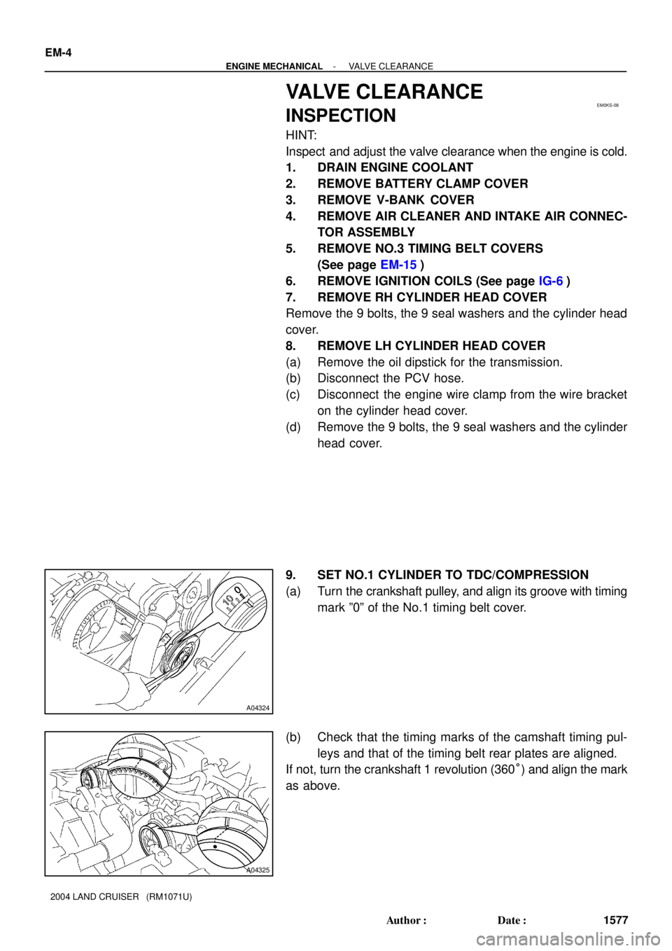
9. SET NO.1 CYLINDER TO TDC/COMPRESSION
(a) Turn the crankshaft pulley, and align its groove with timing
mark º0º of the No.1 timing belt cover.
(b) Check that the timing marks of the camshaft timing pul-
leys and that of the timing belt rear plates are aligned.
If not, turn the crankshaft 1 revolution (360°) and align the mark
as above.
Page 2448 of 3115

B16233
Recommended Viscosity (SAE):
TEMPERATURE RANGE ANTICIPATED BEFORE NEXT OIL CHANGE5W-30°C °F
-20
-290
-1820
-740
460
1680
27100
38
LU08N-04
B04468
Front
B04469
Oil Pressure Gauge
Oil Pressure Switch
P08343
Adhesive
- LUBRICATIONOIL AND FILTER
LU-1
1782 Author�: Date�:
2004 LAND CRUISER (RM1071U)
OIL AND FILTER
INSPECTION
1. CHECK ENGINE OIL QUALITY
Check the oil for deterioration, entry of water, discoloring or thin-
ning.
If the quality is visibly poor, replace the oil.
Oil grade:
API grade SL Energy-Conserving or ILSAC multi-
grade engine oil.
2. CHECK ENGINE OIL LEVEL
The oil level should be between the ºLº and ºFº marks on the dip-
stick.
If low, check for leakage and add oil up to the ºFº mark.
NOTICE:
�Do not fill with engine oil above the ºFº mark.
�Install the oil dipstick facing the direction shown in
the illustration.
3. REMOVE ENGINE UNDER COVER NO.1
4. REMOVE OIL PRESSURE SWITCH
5. INSTALL OIL PRESSURE GAUGE
6. WARM UP ENGINE
Allow the engine to warm up to normal operating temperature.
7. CHECK OIL PRESSURE
Oil pressure:
At idle: 29 kPa (0.3 kgf/cm
2, 4.2 psi) or more
At 3,000 rpm:
294 - 588 kPa (3.0 - 6.0 kgf/cm
2,
43 - 85 psi)
8. REMOVE OIL PRESSURE GAUGE
9. REINSTALL OIL PRESSURE SWITCH
(a) Apply adhesive to 2 or 3 threads of the oil pressure switch.
Adhesive:
Part No. 08833-00080, THREE BOND 1344, LOCTITE
242 or equivalent
(b) Reinstall the oil pressure switch.
10. START ENGINE, AND CHECK FOR ENGINE OIL
LEAKS
11. REINSTALL ENGINE UNDER COVER NO.1