Page 45 of 3115
AC1IO-03
N04963
Dial Indicator AC-66
- AIR CONDITIONINGCOMPRESSOR AND MAGNETIC CLUTCH
2791 Author�: Date�:
2004 LAND CRUISER (RM1071U)
REASSEMBLY
Reassembly is in the reverse of disassembly
(See page AC-63).
AFTER REASSEMBLY, CHECK MAGNETIC CLUTCH
CLEARANCE
(a) Set the dial indicator to the pressure plate of the magnetic
clutch.
(b) Connect the magnetic clutch lead wire to the battery posi-
tive (+) terminal.
(c) Check the clearance between the pressure plate and ro-
tor when connecting the negative (-) terminal to the bat-
tery.
Standard clearance:
0.5 ± 0.15 mm (0.020 ± 0.0059 in.)
If the clearance is not within the standard clearance, adjust the
clearance using shims to obtain the standard clearance.
Shim thickness:
0.1 mm (0.004 in.)
0.3 mm (0.012 in.)
0.5 mm (0.020in.)
Page 46 of 3115
AC1IM-03
I06808
I06811
AC-62
- AIR CONDITIONINGCOMPRESSOR AND MAGNETIC CLUTCH
2787 Author�: Date�:
2004 LAND CRUISER (RM1071U)
REMOVAL
1. RUN ENGINE AT IDLE SPEED WITH A/C ON FOR
APPROX. 10 MINUTES
2. STOP ENGINE
3. DISCONNECT NEGATIVE (- ) TERMINAL CABLE
FROM BATTERY
4. DISCHARGE REFRIGERANT FROM REFRIGERATION
SYSTEM
5. REMOVE ENGINE UNDER COVER
6. REMOVE DRIVE BELT (See page AC-16)
7. DISCONNECT DISCHARGE AND SUCTION HOSES
Remove the 2 bolts and disconnect the both hoses.
NOTICE:
Cap the open fittings immediately to keep moisture or dirt
out of the system.
8. REMOVE FRONT DRIVE SHAFT LH
(See page SA-26)
9. REMOVE COMPRESSOR
(a) Disconnect the connector.
(b) Remove the 3 bolts and the compressor.
Page 76 of 3115
I25040
Relay BlockJunction Block
(Built-in Relay)AC1LY-03
I25183
Engine Room J/B
63
65
57 AC-96
- AIR CONDITIONINGMAGNETIC CLUTCH RELAY
2821 Author�: Date�:
2004 LAND CRUISER (RM1071U)
MAGNETIC CLUTCH RELAY
INSPECTION
HINT:
The magnetic clutch relay is built in the engine room junction
block. Since the relay is constructed with a relay block that is in
the junction block as a unit, it is impossible to disconnect the
wire harness connecting with the relay block.
If the relay has a malfunction, replace it with the junction block
assembly wire harness together.
1. REMOVE ENGINE ROOM J/B
2. INSPECT MAGNETIC CLUTCH RELAY CONTINUITY
ConditionTester connectionSpecified condition
Constant57 - 65Continuity
Apply B+ between
terminals 57 and 65.63 - 65Continuity
If continuity is not as specified, replace the engine room J/B.
3. INSTALL ENGINE ROOM J/B
Page 84 of 3115
AC3OW-01
I25168
1
23
4
Z13470
Magnetic clutch control
Low Pressure Side
ON (Continuity)
196 kpa
(2.0 kgf/cm
2, 28 psi)
OFF (No Continuity)High Pressure Side
3,140 kpa
(32.0 kgf/cm2, 455 psi)
OFF (No Continuity)
- AIR CONDITIONINGPRESSURE SWITCH
AC-91
2816 Author�: Date�:
2004 LAND CRUISER (RM1071U)
PRESSURE SWITCH
ON-VEHICLE INSPECTION
1. SET VEHICLE IN THESE CONDITION
(a) Engine speed at 1,500 rpm
(b) Blower speed control switch at ºHIº position
(c) Temperature control dial at ºMAX. COOLº position
(d) Manifold gauge set setting
2. INSPECT PRESSURE SWITCH OPERATION
(a) Disconnect the connector.
(b) Inspect pressure switch continuity (Magnetic Clutch Con-
trol)
(1) Connect the positive (+) lead from the ohmmeter to
terminal 1 and the negative (-) lead to terminal 2.
(2) Check continuity between terminals when the re-
frigerant pressure is changed, as shown in the il-
lustration.
If continuity is not as specified, replace the pressure switch.
Page 119 of 3115
AT07M-02
D12728
Clutch No.2 (C2) Clutch No.3 (C
3)
Clutch No.1 (C
1)One-way Clutch
No.1 (F1)
One-way Clutch
No.2 (F
2)
Brake No.3
(B
3)
Brake No.1 (B1)
Brake No.2 (B2)One-way Clutch
No.3 (F
3)Brake No.4 (B4)
Shift Solenoid Valve SLT
Shift Solenoid Valve SL1Shift Solenoid Valve S1
Shift Solenoid Valve S2Shift Solenoid Valve SR Shift Solenoid Valve SL2Shift Solenoid Valve SLU
AT-2
- AUTOMATIC TRANSMISSIONAUTOMATIC TRANSMISSION SYSTEM
1853 Author�: Date�:
2004 LAND CRUISER (RM1071U)
OPERATION
Page 125 of 3115

80 (820, 59)
80 (820, 59)
80 (820, 59)
Front Propeller Shaft
48 (490, 35)
Hole Plug
18 (")
AT080-04
D13664
Air Cleaner Cap
Radiator Reservoir
Fan and Fluid
Coupling Assembly
Fan Shroud
x6x4
80 (820, 59)
80 (820, 59)
80 (820, 59)
80 (820, 59)
Front Propeller Shaft
48 (490, 35)
Hole Plug
18 (185, 13)
Torque Converter
Clutch
50 (510, 37)
74 (750, 54)
50 (510, 37)
N´m (kgf´cm, ft´lbf) : Specified torque
� Non-reusable partTransfer Case Protector
Engine Mouting
Insulator RRx4 x6
37 (377, 27)
71 (724, 52)
�LH Front Exhaust Pipe
�
�
� Transmission
with Transfer
106 (1,080, 78)
106 (1,080, 78)
106 (1,080, 78)
Ground
Cable
Transmission
Shift Control Rod
Pin
Rear Propeller Shaft
�
��
� RH Front Exhaust Pipe
Transfer Shift
Lever Boot
Upper Console Panel Transfer Shift Lever Knob
5.4 (55, 48 in.´lbf)
Clip
Transfer Shift
Lever
Engine No. 1
Under Cover
Crossmember
12 (122, 9)
59 (600, 43)
29 (296, 21)
Engine No. 2
Under Cover �
20 (204, 15)
34 (347, 25)
Oil Cooler Pipe
29 (296, 21)29 (296, 21)
- AUTOMATIC TRANSMISSIONAUTOMATIC TRANSMISSION UNIT
AT-29
1883 Author�: Date�:
2004 LAND CRUISER (RM1071U)
AUTOMATIC TRANSMISSION UNIT
COMPONENTS
Page 126 of 3115
D01624
AT082-06
- AUTOMATIC TRANSMISSIONAUTOMATIC TRANSMISSION UNIT
AT-33
1887 Author�: Date�:
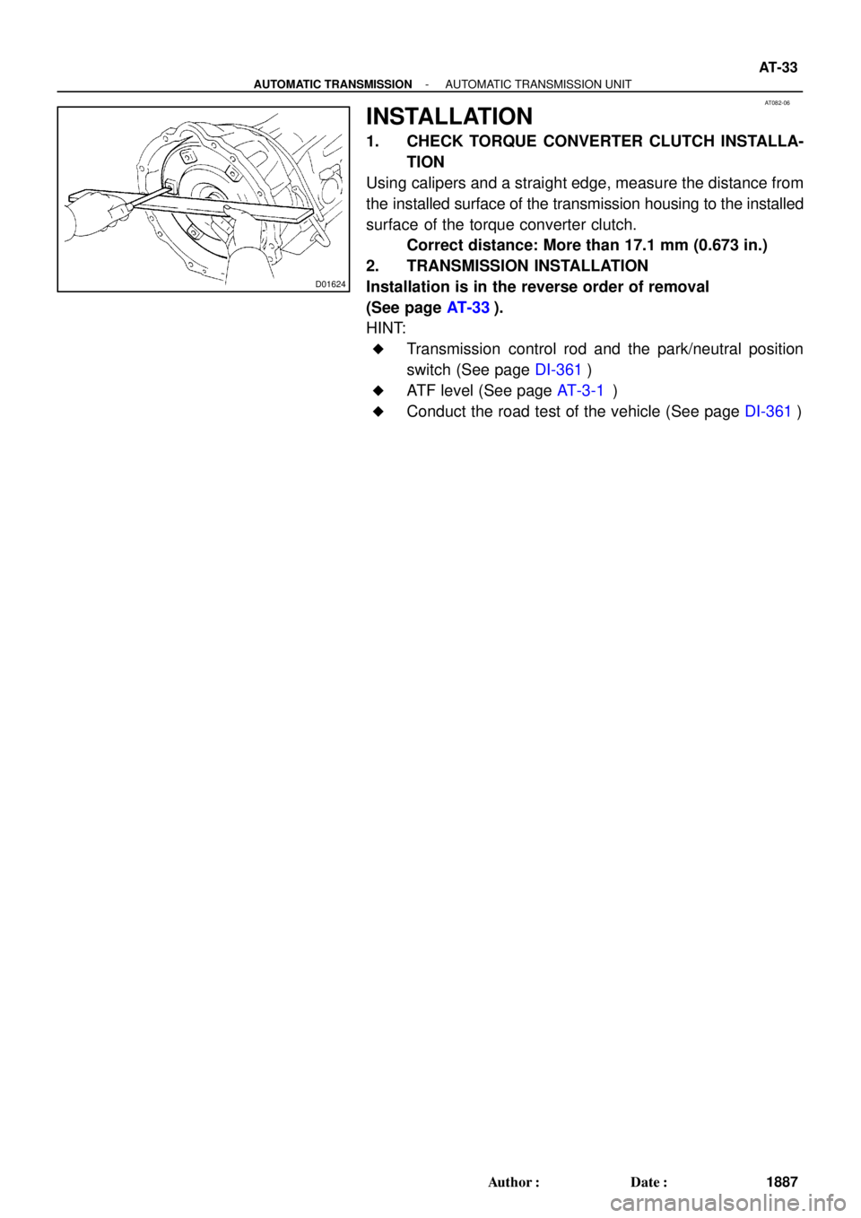
INSTALLATION
1. CHECK TORQUE CONVERTER CLUTCH INSTALLA-
TION
Using calipers and a straight edge, measure the distance from
the installed surface of the transmission housing to the installed
surface of the torque converter clutch.
Correct distance: More than 17.1 mm (0.673 in.)
2. TRANSMISSION INSTALLATION
Installation is in the reverse order of removal
(See page AT-33).
HINT:
�Transmission control rod and the park/neutral position
switch (See page DI-361)
�ATF level (See page AT-3-1)
�Conduct the road test of the vehicle (See page DI-361)
Page 128 of 3115
(b)
(a)
(a)
(b)(b)
D12657
D12658
D12659
(c)(b)
D12660
- AUTOMATIC TRANSMISSIONAUTOMATIC TRANSMISSION UNIT
AT-31
1885 Author�: Date�:
2004 LAND CRUISER (RM1071U)
10. SEPARATE WIRE HARNESS
(")
D12656
(a)(b)
(a)
(a)
(b)(b)
D12657
D12658
D12659
(c)(b)
D12660
- AUTOMATIC TRANSMISSIONAUTOMATIC TRANSMISSION UNIT
AT-31
1885 Author�: Date�:
2004 LAND CRUISER (RM1071U)
10. SEPARATE WIRE HARNESS
(a) Disconnect 3 connectors.
(b) Remove the 3 clamps from the transmission unit and sep-
arate the transmission wire.
11. REMOVE TORQUE CONVERTER CLUTCH MOUNT-
ING BOLT
(a) Remove the bolt and the hole plug.
Torque: 18 N´m (185 kgf´cm, 13 ft´lbf)
(b) Turn the crankshaft to gain access to each bolt.
(c) Hold the crankshaft pulley nut with a wrench, and remove
the 6 bolts.
Torque: 48 N´m (490 kgf´cm, 35 ft´lbf)
HINT:
At the time of installation, first install the green colored bolt. And
then install the other 5 bolts.
12. DISCONNECT OIL COOLER PIPES
(a) Loosen the 2 union nuts.
(b) Remove the bolt and the clamp.
Torque: 12 N´m (122 kgf´cm, 9 ft´lbf)
(c) Remove the 2 union nuts and disconnect the 2 oil cooler
pipes.
Torque: 34 N´m (347 kgf´cm, 25 ft´lbf)
13. SEPARATE GROUND CABLE
Remove the bolt and separate the ground cable.
Torque: 20 N´m (204 kgf´cm, 15 ft´lbf)
14. REMOVE CROSSMEMBER AND TRANSTER CASE
PROTECTOR
(a) Support the transmission with a jack.


196 kpa
(2.0 kgf/cm
2, 28 psi)
OFF (No Continuity)High Pressure Side
3,140 kpa
(32.0 kgf/cm2, 455 psi)
OFF (No C")
 Clutch No.3 (C
3)
Clutch No.1 (C
1)One-way Clutch
No.1 (F1)
One-way Clutch
No.2 (F
2)
Brake No.3
(B
3)
Brake No.1 (B1)
Brake No.2 (B2)One-way Clutch
No.3 (F
3)Brake No")