Page 3026 of 3115
SA1DA-04
F05258
RH Case:LH Case:
X
X
F05259
SST
Y SA-150
- SUSPENSION AND AXLEREAR DIFFERENTIAL CARRIER (w/ LSD)
2100 Author�: Date�:
2004 LAND CRUISER (RM1071U)
REASSEMBLY
HINT:
�When reusing the side gear, thrust washers and clutch
plates, skip the STEP 1.
�Using a shop rag, clean off any foreign object from the
parts.
�Apply all of the sliding and rotating surfaces with LSD oil.
1. SELECT ADJUSTING SHIM
(a) Measure the RH and LH differential case dimensions ºXº,
as shown in the illustration.
(b) Install the thrust washers and clutch plates on the side
gear.
(c) Using SST to press down the thrust washers and clutch
plates with about pressure of 10 kgf (22 lbf), measure di-
mension ºYº, as shown in the illustration.
SST 09649-17010
(d) Referring to the following selection table on the next
page, select the proper adjusting shim.
Adjust shim thickness =
X - Y - 19.08 mm (0.7511 in.)
Page 3029 of 3115

SA-153
2103 Author�: Date�:
2004 LAND CRUISER (RM1071U)
Adjust shim thickness:
MarkThickness mm (in.)MarkThickness")
W01877
W01878
- SUSPENSION AND AXLEREAR DIFFERENTIAL CARRIER (w/ LSD)
SA-153
2103 Author�: Date�:
2004 LAND CRUISER (RM1071U)
Adjust shim thickness:
MarkThickness mm (in.)MarkThickness mm (in.)
A0.20 (0.0079)C0.30 (0.0118)
B0.25 (0.0098)D0.35 (0.0138)
2. CHECK SIDE GEAR BACKLASH
(a) Install the thrust washers, clutch plates and adjusting
shim to side gear.
HINT:
Install the adjusting shim with its surface having no oil groove
facing to the differential case side.
(b) Install the side gear to the differential case.
(c) Install the 4 pinion gears and thrust washers to the spider.
(d) Align the spring retainer holes with the straight pins and
install the retainer.
(e) Install the spider to the differential case.
HINT:
Install the spider to the differential case tightly and do not move
the spring retainer.
(f) Using a dial indicator, measure the side gear backlash
while holding the side gear and spider.
Backlash: 0.02 - 0.15 mm (0.0008 - 0.0059 in.)
HINT:
�Measure at all 4 locations.
�Measure the backlash at the RH and LH differential
cases.
If the backlash is not within the specified value, select the ad-
justing shim.
3. ASSEMBLE DIFFERENTIAL CASE
(a) Reinstall the spider to the LH differential case.
HINT:
Install the spider to the LH differential case tightly and do not
move the spring retainer.
(b) Install the compression spring and RH spring retainer.
(c) Install the RH side gear.
(d) Align the matchmarks and assemble the RH and LH dif-
ferential cases.
Page 3065 of 3115
TR06J-02
D04344
Front Drive
Gear Piece
� Snap RingFront Taper
Roller BearingNeedle Roller BearingClutch Hub High Speed Output
Gear Bushing High Speed
Output Gear
Rear Taper
Roller Bearing
x12
Differential
Rear Case
Pinion ShaftRear Side
Gear
: Specified torqueThrust Washer
Front Side Gear
N´m (kgf´cm, ft´lbf)Straight Pin
Low GearStraight PinHigh and Low
Clutch Sleeve
Thrust Washer
Thrust Washer Thrust Washer
� Non-reusable partPinion Gear
Differential
Front Case
See page TR-31
Pinion Gear
- TRANSFERCENTER DIFFERENTIAL
TR-27
1915 Author�: Date�:
2004 LAND CRUISER (RM1071U)
CENTER DIFFERENTIAL
COMPONENTS
Page 3067 of 3115
D02680
Q07103
SST
Q07113
SST
D02681
D02682
- TRANSFERCENTER DIFFERENTIAL
TR-29
1917 Author�: Date�:
2004 LAND CRUISER (RM1071U)
6. REMOVE HIGH AND LOW CLUTCH SLEEVE
7. REMOVE HIGH SPEED OUTPUT GEAR BUSHING
AND CLUTCH HUB
(a) Using SST, remove the high speed output gear bushing
and clutch hub.
SST 09950- 00020, 09950- 00030, 09950- 60010
(09951-00320)
(b) Using a magnetic finger, remove the straight pin from the
differential front case.
8. REMOVE REAR TAPER ROLLER BEARING
Using SST and a press, remove the rear taper roller bearing.
SST 09950-00020, 09950-60010 (09951-00320)
NOTICE:
Set the claw of SST to the bearing inner race securely.
9. REMOVE DIFFERENTIAL REAR CASE
Remove the 12 bolts and differential rear case.
10. REMOVE THRUST WASHER AND REAR SIDE GEAR
Page 3070 of 3115

(b) Using a dial indicator, measure the front case backlash.
HINT:
Push t")
TF0917
TF0920
Q00534
SST
Q00547
SST
SST
TR-32
- TRANSFERCENTER DIFFERENTIAL
1920 Author�: Date�:
2004 LAND CRUISER (RM1071U)
(b) Using a dial indicator, measure the front case backlash.
HINT:
Push the pinion shaft.
Maximum backlash: 0.05 mm (0.0020 in.)
If the backlash is not within the specification, replace the thrust
washer with one of the correct size and reinstall the thrust wash-
er.
Thickness mm (in.)Thickness mm (in.)
1.70 (0.0669)2.45 (0.0965)
1.85 (0.0728)2.60 (0.1024)
2.00 (0.0787)2.75 (0.1083)
2.15 (0.0846)2.90 (0.1142)
2.30 (0.0906)3.05 (0.1201)
(c) In the same way, measure the rear case backlash.
4. INSTALL STRAIGHT PIN TO PINION SHAFT
5. INSTALL REAR SIDE GEAR AND THRUST WASHER
6. INSTALL DIFFERENTIAL REAR CASE
(a) Install the differential rear case and 12 set bolts.
Torque: 88 N´m (900 kgf´cm, 65 ft´lbf)
(b) Turn the pinion gear.
(c) Loosen the 12 rear case set bolts.
(d) Torque the 12 rear case set bolts.
Torque: 98 N´m (1,000 kgf´cm, 72 ft´lbf)
7. INSTALL REAR TAPER ROLLER BEARING
Using SST and a press, install the rear taper roller bearing.
SST 09316-12010
8. INSTALL CLUTCH HUB
Using SST and a press, install the clutch hub.
SST 09316-12010, 09316-60011 (09316-00011)
Page 3071 of 3115
Q00549
D04312
Pin Groove
SST
Q00555
Q00539
SST
SST
- TRANSFERCENTER DIFFERENTIAL
TR-33
1921 Author�: Date�:
2004 LAND CRUISER (RM1071U)
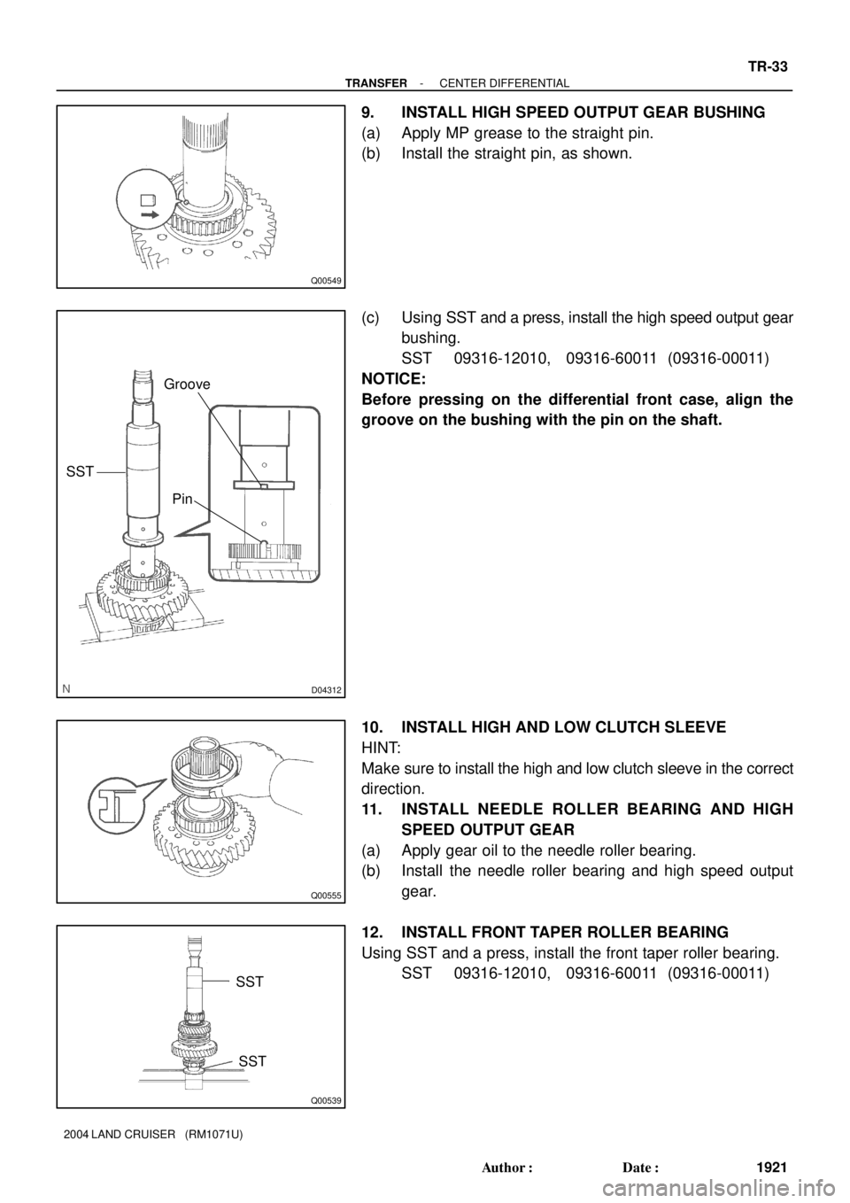
9. INSTALL HIGH SPEED OUTPUT GEAR BUSHING
(a) Apply MP grease to the straight pin.
(b) Install the straight pin, as shown.
(c) Using SST and a press, install the high speed output gear
bushing.
SST 09316-12010, 09316-60011 (09316-00011)
NOTICE:
Before pressing on the differential front case, align the
groove on the bushing with the pin on the shaft.
10. INSTALL HIGH AND LOW CLUTCH SLEEVE
HINT:
Make sure to install the high and low clutch sleeve in the correct
direction.
11. INSTALL NEEDLE ROLLER BEARING AND HIGH
SPEED OUTPUT GEAR
(a) Apply gear oil to the needle roller bearing.
(b) Install the needle roller bearing and high speed output
gear.
12. INSTALL FRONT TAPER ROLLER BEARING
Using SST and a press, install the front taper roller bearing.
SST 09316-12010, 09316-60011 (09316-00011)
Page 3073 of 3115
TR06M-02
Z18836
Front Output Shaft� Dust Deflector
� Oil SealFront Extension HousingBall Bearing� Snap RingDrive Clutch Hub� Snap Ring
��Non-reusable part
- TRANSFERFRONT EXTENSION HOUSING
TR-35
1923 Author�: Date�:
2004 LAND CRUISER (RM1071U)
FRONT EXTENSION HOUSING
COMPONENTS
Page 3074 of 3115
Q07133
SST
TR06N-03
TF1036
D02660
SST
TF0937
TF0938
TR-36
- TRANSFERFRONT EXTENSION HOUSING
1924 Author�: Date�:
2004 LAND CRUISER (RM1071U)
DISASSEMBLY
1. REMOVE DRIVE CLUTCH HUB
(a) Using a snap ring expander, remove the snap ring.
(b) Using SST, remove the drive clutch hub.
SST 09950- 40011 (09951- 04020, 09952- 04010,
09953- 04030, 09954- 04020, 09955- 04021,
09957-04010, 09958-04011)
2. REMOVE FRONT OUTPUT SHAFT
Using a plastic hammer, drive out the front output shaft.
3. REMOVE DUST DEFLECTOR
(a) Using SST, remove the dust deflector.
SST 09950- 40011 (09951- 04020, 09952- 04010,
09953- 04030, 09954- 04010, 09955- 04051,
09957-04010, 09958-04011)
(b) Using a screwdriver and hammer, tap the dust deflector
and remove it from the extension housing.
4. REMOVE OIL SEAL
Using a screwdriver, pry out the oil seal from the front extension
housing.