Page 812 of 3115
F02836
GND1
GND2GND3
GND4
F04448
Driver Side J/B
ECU-IG
DI-560- DIAGNOSTICSABS & VEHICLE STABILITY CONTROL (VSC) &
BRAKE ASSIST (BA) SYSTEM
753 Author�: Date�:
2004 LAND CRUISER (RM1071U)
3 Check continuity between terminal GND of skid control ECU connector and body
ground.
CHECK:
Measure resistance between terminal GND of the skid control
ECU connector and body ground.
OK:
Resistance: 1 W or less
NG Repair or replace harness or connector.
OK
4 Check ECU-IG fuse.
PREPARATION:
Remove the ECU-IG fuse from the driver side J/B.
CHECK:
Check continuity of the ECU-IG fuse.
OK:
Continuity
NG Check for short circuit in all the harness and
components connected to ECU-IG fuse (See at-
tached wiring diagram).
OK
Check for open circuit in harness and connector between skid control ECU and battery (See page
IN-36).
Page 856 of 3115
F02836
GND1
GND2GND3
GND4
F04448
Driver Side J/B
ECU-IG
DI-604- DIAGNOSTICSABS & VEHICLE STABILITY CONTROL (VSC) &
BRAKE ASSIST (BA) SYSTEM
797 Author�: Date�:
2004 LAND CRUISER (RM1071U)
3 Check continuity between terminal GND of skid control ECU connector and body
ground.
CHECK:
Measure resistance between terminal GND of the skid control
ECU connector and body ground.
OK:
Resistance: 1 W or less
NG Repair or replace harness or connector.
OK
4 Check ECU-IG fuse.
PREPARATION:
Remove the ECU-IG fuse from the driver side J/B.
CHECK:
Check continuity of the ECU-IG fuse.
OK:
Continuity
NG Check for short circuit in all the harness and
components connected to ECU-IG fuse (See at-
tached wiring diagram).
OK
Check for open circuit in harness and connector between skid control ECU and battery (See page
IN-36).
Page 1340 of 3115
A21371
Battery1BB-R
E9ECM
BATT 13
IG1 1
Id15
F15
FL Block 2Engine Room J/B
MAIN
B-G
1CEFI or ECD No. 1
3
B-R B-R
A19976
Engine Room J/B
EFI or ECD No. 1 Fuse
- DIAGNOSTICSENGINE
DI-291
484 Author�: Date�:
2004 LAND CRUISER (RM1071U)
WIRING DIAGRAM
INSPECTION PROCEDURE
HINT:
Read freeze frame data using the hand-held tester or the OBD II scan tool. Freeze frame data records the
engine conditions when a malfunction is detected. When troubleshooting, freeze frame data can help deter-
mine if the vehicle was running or stopped, if the engine was warmed up or not, if the air-fuel ratio was lean
or rich, as well as other data from the time when a malfunction occurred.
1 Check EFI or ECD No. 1 fuse of engine room J/B.
PREPARATION:
Remove the EFI or ECD No. 1 fuse from the engine room J/B.
CHECK:
Check the continuity of the EFI or ECD No. 1 fuse.
OK:
Continuity
NG Check for short in all harness and components
connected to EFI or ECD No. 1 fuse.
OK
Page 1916 of 3115

2004 LAND CRUISER (EWD548U)
9 B
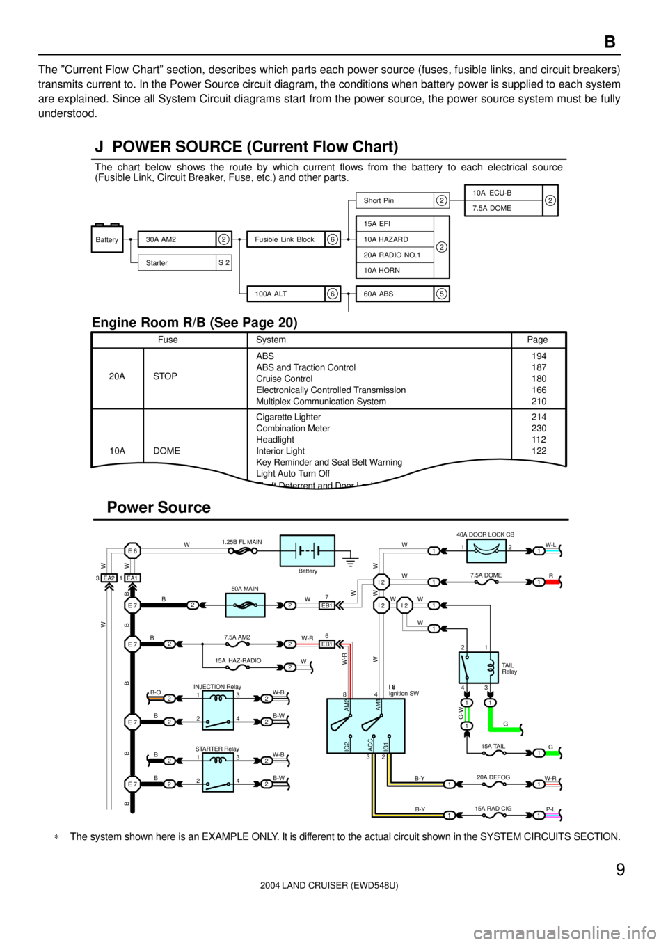
The ºCurrent Flow Chartº section, describes which parts each power source (fuses, fusible links, and circuit breakers)
transmits current to. In the Power Source circuit diagram, the conditions when battery power is supplied to each system
are explained. Since all System Circuit diagrams start from the power source, the power source system must be fully
understood.
ACC
S 26
652
22
Battery30A AM2
StarterShort Pin
100A ALT Fusible Link Block
60A ABS10A ECU-B
7.5A DOME
15A EFI
10A HAZARD
20A RADIO NO.1
10A HORN
20A
10AFusePage
214
230
11 2
122 194
187
180
166
210 ABS
Cigarette Lighter
Combination Meter
Key Reminder and Seat Belt Warning
Light Auto Turn Off
Theft Deterrent and Door Lock ControlABS and Traction Control
Cruise Control
Electronically Controlled Transmission
Multiplex Communication System STOPSystem
DOMEHeadlight
Interior Light
3 EA2 1 EA1E 6
E 7
E 7
2
2
2
2 2
2 2
2 INJECTION Relay
STARTER Relay B
B
B B-O
1
1 2
23
4
3
4W-B W-B
B-W
B-W E 7
E 7B
BW1.25B FL MAIN
50A MAIN
7.5A AM2
15A HAZ-RADIO 2
22
2
2W
WEB1
EB17
6
W-RI 2 I 2 I 2
WW
W W W
1 1
1 140A DOOR LOCK CB
7.5A DOME 1W-L
R 1
1
2
431
1 1
1
111 G
G
W-R 15A TAIL
20A DEFOG
B-Y 84
32Ignition SW I 8
B-Y
11P-L Battery
15A RAD CIG2
TAIL
Relay
Power Source J POWER SOURCE (Current Flow Chart)
Engine Room R/B (See Page 20)
2
W W
B B B B B
W-R
WW W
G-WAM2
AM1 IG2
IG1W
W
The chart below shows the route by which current flows from the battery to each electrical source
(Fusible Link, Circuit Breaker, Fuse, etc.) and other parts.
*The system shown here is an EXAMPLE ONLY. It is different to the actual circuit shown in the SYSTEM CIRCUITS SECTION.