Page 1900 of 3115

A04339
A05707
Slightly Turn
A04340
SST
A04341
SST
A04448
EM-18
- ENGINE MECHANICALTIMING BELT
1591 Author�: Date�:
2004 LAND CRUISER (RM1071U)
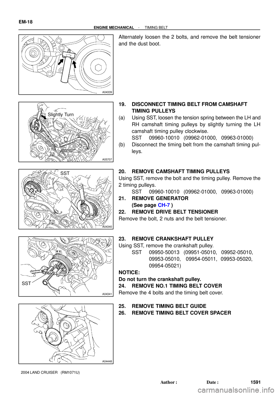
Alternately loosen the 2 bolts, and remove the belt tensioner
and the dust boot.
19. DISCONNECT TIMING BELT FROM CAMSHAFT
TIMING PULLEYS
(a) Using SST, loosen the tension spring between the LH and
RH camshaft timing pulleys by slightly turning the LH
camshaft timing pulley clockwise.
SST 09960-10010 (09962-01000, 09963-01000)
(b) Disconnect the timing belt from the camshaft timing pul-
leys.
20. REMOVE CAMSHAFT TIMING PULLEYS
Using SST, remove the bolt and the timing pulley. Remove the
2 timing pulleys.
SST 09960-10010 (09962-01000, 09963-01000)
21. REMOVE GENERATOR
(See page CH-7)
22. REMOVE DRIVE BELT TENSIONER
Remove the bolt, 2 nuts and the belt tensioner.
23. REMOVE CRANKSHAFT PULLEY
Using SST, remove the crankshaft pulley.
SST 09950-50013 (09951-05010, 09952-05010,
09953-05010, 09954-05011, 09953-05020,
09954-05021)
NOTICE:
Do not turn the crankshaft pulley.
24. REMOVE NO.1 TIMING BELT COVER
Remove the 4 bolts and the timing belt cover.
25. REMOVE TIMING BELT GUIDE
26. REMOVE TIMING BELT COVER SPACER
Page 1901 of 3115
A04342
A04444
A04445SST
- ENGINE MECHANICALTIMING BELT
EM-19
1592 Author�: Date�:
2004 LAND CRUISER (RM1071U)
27. REMOVE TIMING BELT
HINT:
If re-using the belt and the installation mark is disappeared
from it, place a new installation mark on the timing belt to the
match the dot mark on the crankshaft timing pulley.
28. REMOVE NO.1 IDLER PULLEY AND NO.2 IDLER
PULLEY
(a) Using a 10 mm hexagon wrench, remove the bolt, the
No.1 idler pulley and the plate washer.
(b) Remove the bolt and the No.2 idler pulley.
29. REMOVE CRANKSHAFT TIMING PULLEY
Using SST, remove the timing pulley.
SST 09950-50013 (09951-05010, 09952-05010,
09953-05010, 09953-05020, 09954-05011,
09954-05021)
NOTICE:
Do not turn the timing pulley.
Page 1902 of 3115

EM0KS-08
A04324
A04325
EM-4
- ENGINE MECHANICALVALVE CLEARANCE
1577 Author�: Date�:
2004 LAND CRUISER (RM1071U)
VALVE CLEARANCE
INSPECTION
HINT:
Inspect and adjust the valve clearance when the engine is cold.
1. DRAIN ENGINE COOLANT
2. REMOVE BATTERY CLAMP COVER
3. REMOVE V-BANK COVER
4. REMOVE AIR CLEANER AND INTAKE AIR CONNEC-
TOR ASSEMBLY
5. REMOVE NO.3 TIMING BELT COVERS
(See page EM-15)
6. REMOVE IGNITION COILS (See page IG-6)
7. REMOVE RH CYLINDER HEAD COVER
Remove the 9 bolts, the 9 seal washers and the cylinder head
cover.
8. REMOVE LH CYLINDER HEAD COVER
(a) Remove the oil dipstick for the transmission.
(b) Disconnect the PCV hose.
(c) Disconnect the engine wire clamp from the wire bracket
on the cylinder head cover.
(d) Remove the 9 bolts, the 9 seal washers and the cylinder
head cover.
9. SET NO.1 CYLINDER TO TDC/COMPRESSION
(a) Turn the crankshaft pulley, and align its groove with timing
mark º0º of the No.1 timing belt cover.
(b) Check that the timing marks of the camshaft timing pul-
leys and that of the timing belt rear plates are aligned.
If not, turn the crankshaft 1 revolution (360°) and align the mark
as above.
Page 1903 of 3115

A05717
RH Cylinder Head
LH Cylinder HeadFront
A04457
RH Cylinder Head
LH Cylinder HeadFront
A02213
- ENGINE MECHANICALVALVE CLEARANCE
EM-5
1578 Author�: Date�:
2004 LAND CRUISER (RM1071U)
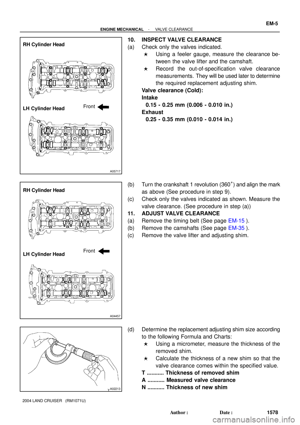
10. INSPECT VALVE CLEARANCE
(a) Check only the valves indicated.
�Using a feeler gauge, measure the clearance be-
tween the valve lifter and the camshaft.
�Record the out-of-specification valve clearance
measurements. They will be used later to determine
the required replacement adjusting shim.
Valve clearance (Cold):
Intake
0.15 - 0.25 mm (0.006 - 0.010 in.)
Exhaust
0.25 - 0.35 mm (0.010 - 0.014 in.)
(b) Turn the crankshaft 1 revolution (360°) and align the mark
as above (See procedure in step 9).
(c) Check only the valves indicated as shown. Measure the
valve clearance. (See procedure in step (a))
11. ADJUST VALVE CLEARANCE
(a) Remove the timing belt (See page EM-15).
(b) Remove the camshafts (See page EM-35).
(c) Remove the valve lifter and adjusting shim.
(d) Determine the replacement adjusting shim size according
to the following Formula and Charts:
�Using a micrometer, measure the thickness of the
removed shim.
�Calculate the thickness of a new shim so that the
valve clearance comes within the specified value.
T ........... Thickness of removed shim
A ........... Measured valve clearance
N ........... Thickness of new shim
Page 1904 of 3115
EM-6
- ENGINE MECHANICALVALVE CLEARANCE
1579 Author�: Date�:
2004 LAND CRUISER (RM1071U)
Intake:
N = T + (A - 0.20 mm (0.008 in.))
Exhaust:
N = T + (A - 0.30 mm (0.012 in.))
�Select a new shim with the closest thickness as
close as possible to the calculated value.
HINT:
Shims are available in 41 increments of 0.020 mm (0.0008 in.),
from 2.00 mm (0.0787 in.) to 2.80 mm (0.1102 in.).
(e) Place a new adjusting shim on the valve.
(f) Place the valve lifter.
(g) Reinstall the camshafts (See page EM-57).
(h) Reinstall the timing belt (See page EM-22).
(i) Recheck the valve clearance.
12. REINSTALL CYLINDER HEAD COVERS
13. REINSTALL IGNITION COILS
14. REINSTALL NO.3 TIMING BELT COVERS (See page
EM-22)
15. REINSTALL AIR CLEANER AND INTAKE AIR CON-
NECTOR ASSEMBLY
16. REFILL WITH ENGINE COOLANT
17. START ENGINE AND CHECK FOR LEAKS
18. RECHECK ENGINE COOLANT LEVEL
19. REINSTALL V-BANK COVER
20. REINSTALL BATTERY CLAMP COVER
Page 2389 of 3115
IG08T-03
B06326
V-Bank Cover
7.5 (80, 66 in.´lbf)
: Specified torqueN´m (kgf´cm, ft´lbf) Camshaft Position
Sensor Connector
Grommet
Engine Wire Camshaft Position Sensor
Oil Cooler Pipe
LH No.3 Timing Belt Cover
7.5 (80, 66 in.´lbf)
7.5 (80, 66 in.´lbf)
Fuel Return
Hose
IG-8
- IGNITIONCAMSHAFT POSITION SENSOR
1811 Author�: Date�:
2004 LAND CRUISER (RM1071U)
CAMSHAFT POSITION SENSOR
COMPONENTS
Page 2390 of 3115
IG08V-01
B04078
IG-10
- IGNITIONCAMSHAFT POSITION SENSOR
1813 Author�: Date�:
2004 LAND CRUISER (RM1071U)
INSTALLATION
1. INSTALL CAMSHAFT POSITION SENSOR
Install the camshaft position sensor with the bolt and stud bolt
Torque: 7.5 N´m (80 kgf´cm, 66 in.´lbf)
2. INSTALL LH NO.3 TIMING BELT COVER
(See page EM-22)
3. CONNECT RADIATOR HOSE
4. INSTALL V-BANK COVER
5. FILL ENGINE COOLANT (See page CO-2)
6. CHECK ENGINE COOLANT FOR LEAKS
7. CHECK IGNITION TIMING (See page EM-9)
Page 2391 of 3115
IG08U-01
B04078
- IGNITIONCAMSHAFT POSITION SENSOR
IG-9
1812 Author�: Date�:
2004 LAND CRUISER (RM1071U)
REMOVAL
1. REMOVE V-BANK COVER
2. DRAIN ENGINE COOLANT
3. DISCONNECT UPPER RADIATOR HOSE
4. REMOVE LH NO.3 TIMING BELT COVER
(See page EM-15)
5. REMOVE CAMSHAFT POSITION SENSOR
Remove the bolt, stud bolt and camshaft position sensor.