Page 1876 of 3115

EM-84
- ENGINE MECHANICALENGINE UNIT
1657 Author�: Date�:
2004 LAND CRUISER (RM1071U)
13. CONNECT HOSES, WIRES, CONNECTORS, CLAMPS,
GROMMET AND CABLES
(a) Connect the 2 PS air hoses to the hose clamp on the No.3
RH timing belt cover.
(b) Connect the generator wire.
(c) Connect the generator connector.
(d) Connect the hose clamp for the PS air hose.
(e) Connect the PS air hose to upper intake manifold.
(f) Connect the 2 heater hoses.
(g) Connect the engine wire clamp to the bracket on the cowl
panel.
(h) Connect the engine wire grommet to the cowl panel.
(i) Connect the ground strap connector.
(j) Connect the fuel main hose and the clamps.
(k) Connect the fuel return hose and the clamp.
(l) Connect the air inlet hose to the charcoal canister.
(m) Connect the EVAP hose to the charcoal canister.
(n) Connect the engine wire to the clamp on the right fender
apron.
(o) Connect the clamp on battery negative (-) cable to the
relay box.
(p) Connect the battery negative (-) cable to the right fender
apron.
(q) Connect the battery positive (+) terminal cable.
14. CONNECT ENGINE WIRE TO CABIN
(a) Connect the 3 wire harness connectors.
(b) Install the ECM with the 3 screws.
(c) Connect the 3 connectors to the ECM.
(d) Install the glove compartment door.
(e) Install the lower No.2 panel.
15. INSTALL FAN PULLEY, FAN, FLUID COUPLING AND
GENERATOR DRIVE BELT
(a) Temporarily install the fan pulley, the fan and the fluid cou-
pling assembly with the 4 nuts.
(b) Install the generator drive belt. (See page CH-16)
(c) Tighten the 4 nuts holding the fluid coupling to the fan
bracket.
16. INSTALL RADIATOR AND FAN SHROUD
(a) Place the fan shroud in the installation position.
(b) Install the radiator with the 2 support collars, the 2 nuts
and the 2 bolts.
(c) Connect the 2 A/T oil cooler hoses to the radiator.
(d) Install the lower radiator hose.
(e) Attach the lower side of the fan shroud to the brackets of
the radiator, and install the fan shroud with the 2 bolts.
(f) Install the 2 brackets on the wire to the radiator with the
2 bolts.
(g) Install the 2 clamps on the A/C discharge tube to the
brackets on the wire with the 2 nuts.
Page 1878 of 3115

EM0L9-07
- ENGINE MECHANICALENGINE UNIT
EM-77
1650 Author�: Date�:
2004 LAND CRUISER (RM1071U)
REMOVAL
1. REMOVE HOOD
2. REMOVE ENGINE UNDER COVERS
3. DRAIN ENGINE COOLANT
4. DRAIN ENGINE OIL
5. REMOVE V-BANK COVER
6. REMOVE BATTERY
7. REMOVE AIR CLEANER CAP AND INTAKE AIR CON-
NECTOR PIPE ASSEMBLY
8. REMOVE RADIATOR RESERVOIR
(a) Disconnect the clamp on the wire from the reservoir.
(b) Disconnect the reservoir hose from the radiator.
(c) Remove the 2 bolts, the reservoir and the grommet.
9. REMOVE RADIATOR AND FAN SHROUD
(a) Disconnect the upper radiator hose from the front water
bypass joint.
(b) Remove the 2 nuts, and disconnect the 2 clamps on the
A/C discharge tube from the bracket.
(c) Remove the 2 bolts, and disconnect the 2 brackets on the
wire from the radiator.
(d) Remove the 3 bolts, and disconnect the fan shroud from
the radiator.
(e) Remove the lower radiator hose.
(f) Disconnect the 2 A/T oil cooler hoses from the radiator.
(g) Remove the 2 bolts, the 2 nuts, the 2 support collars and
the radiator.
(h) Remove the fan shroud.
10. REMOVE GENERATOR DRIVE BELT, FAN, FLUID
COUPLING AND FAN PULLEY
(a) Loosen the 4 nuts holding the fluid coupling to the fan
bracket.
(b) Remove the generator drive belt. (See page CH-7)
(c) Remove the 4 nuts, the fan, the fluid coupling assembly
and the fan pulley.
11. DISCONNECT ENGINE WIRE FROM CABIN
(a) Remove the glove compartment door.
(b) Remove the lower No.2 panel.
(c) Disconnect the 3 connectors from the ECM.
(d) Remove the 3 screws, and disconnect ECM from the
body bracket.
(e) Disconnect the 3 wire harness connectors.
12. DISCONNECT HOSES, WIRES, CONNECTORS,
CLAMPS, GROMMET AND CABLES
(a) Disconnect the 2 PS air hoses from the hose clamp on the
No.3 RH timing belt cover.
(b) Disconnect the generator wire.
(c) Disconnect the generator connector.
(d) Disconnect the hose clamp for PS air hose.
(e) Disconnect the PS air hose from upper intake manifold.
Page 1886 of 3115
EM0KV-1 1
A09750
P/S Air HoseRadiator
Reservoir Tank
Intake Air
Connector
Radiator Assembly
EVAP HoseV-Bank Cover
Engine Under Cover No.1
N´m (kgf´cm, ft´lbf) : Specified torque Generator
Drive Belt
A/C CompressorA/C Compressor
Connector
A/T Oil Cooler Hose
Fan w/ Fluid
Coupling
Fan Pulley
49 (500, 36)
5.0 (50, 43 in.´lbf)
18 (185, 13)
Air Hose
x 8Fan Shroud Fuel Return
Hose
20 (200, 15)
A/T Oil Cooler
Hose
A/C Discharge
Tube
Clamp
BracketWireClamp
Clamp
Lower Radiator Hose
Bracket
EM-12
- ENGINE MECHANICALTIMING BELT
1585 Author�: Date�:
2004 LAND CRUISER (RM1071U)
TIMING BELT
COMPONENTS
Page 1887 of 3115
A04326
RH No. 3 Timing Belt Cover
No. 2 Timing
Belt Cover
LH No. 3 Timing Belt Cover Drive Belt Idler Pulley
Camshaft Position
Sensor ConnectorCover Plate
Engine Wire
16 (160, 12)
7.5 (80, 16 in.´lbf)
N´m (kgf´cm, ft´lbf) : Specified torque
Oil Cooler PipeWire Grommet
39 (400, 29)
7.5 (80, 66 in.´lbf)
A04327
Timing BeltRH Camshaft Timing Pulley
LH Camshaft Timing Belt Pulley
Timing belt Tensioner
Fan BracketDust Boot
108 (1,100, 80)
245 (2,500, 181)
16 (160, 12)
32 (330, 24)
26 (270, 19)N´m (kgf´cm, ft´lbf) : Specified torque
- ENGINE MECHANICALTIMING BELT
EM-13
1586 Author�: Date�:
2004 LAND CRUISER (RM1071U)
Page 1888 of 3115
A19486
Generator Wire
Drive Belt Tensioner
No.1 Timing Belt Cover
Generator
Crankshaft Pulley
No.1 Idler Pulley
Timing Belt
Plate Washer
Crankshaft Timing Pulley
Timing Belt Cover Spacer No.2 Idler Pulley Timing Belt Guide
(Crankshaft Angle Sensor Plate)
Gasket
34.5 (350, 25)
�
N´m (kgf´cm, ft´lbf) : Specified torque
� Precoated part
34.5 (350, 25)
39 (400, 29)
39 (400, 29)
15.5 (158, 11)
EM-14
- ENGINE MECHANICALTIMING BELT
1587 Author�: Date�:
2004 LAND CRUISER (RM1071U)
Page 1889 of 3115

EM0KX-06
EM3336
NO !
P20079
P20633
EM-20
- ENGINE MECHANICALTIMING BELT
1593 Author�: Date�:
2004 LAND CRUISER (RM1071U)
INSPECTION
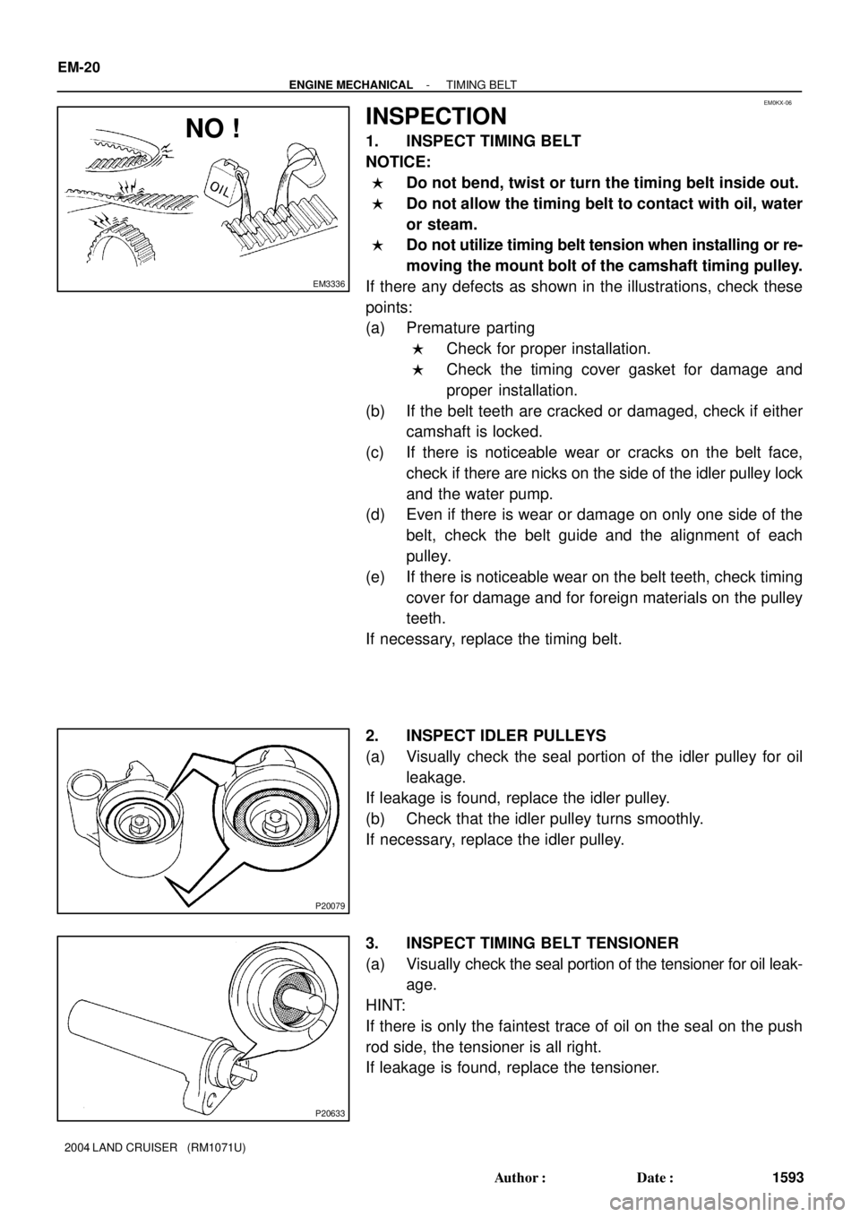
1. INSPECT TIMING BELT
NOTICE:
�Do not bend, twist or turn the timing belt inside out.
�Do not allow the timing belt to contact with oil, water
or steam.
�Do not utilize timing belt tension when installing or re-
moving the mount bolt of the camshaft timing pulley.
If there any defects as shown in the illustrations, check these
points:
(a) Premature parting
�Check for proper installation.
�Check the timing cover gasket for damage and
proper installation.
(b) If the belt teeth are cracked or damaged, check if either
camshaft is locked.
(c) If there is noticeable wear or cracks on the belt face,
check if there are nicks on the side of the idler pulley lock
and the water pump.
(d) Even if there is wear or damage on only one side of the
belt, check the belt guide and the alignment of each
pulley.
(e) If there is noticeable wear on the belt teeth, check timing
cover for damage and for foreign materials on the pulley
teeth.
If necessary, replace the timing belt.
2. INSPECT IDLER PULLEYS
(a) Visually check the seal portion of the idler pulley for oil
leakage.
If leakage is found, replace the idler pulley.
(b) Check that the idler pulley turns smoothly.
If necessary, replace the idler pulley.
3. INSPECT TIMING BELT TENSIONER
(a) Visually check the seal portion of the tensioner for oil leak-
age.
HINT:
If there is only the faintest trace of oil on the seal on the push
rod side, the tensioner is all right.
If leakage is found, replace the tensioner.
Page 1890 of 3115
P20634
P20635
Protrusion
- ENGINE MECHANICALTIMING BELT
EM-21
1594 Author�: Date�:
2004 LAND CRUISER (RM1071U)
(b) Hold the tensioner with both hands, and push the push
rod strongly to check that it doesn't move.
If the push rod moves, replace the tensioner.
NOTICE:
Never hold the tensioner push rod facing downward.
(c) Measure the protrusion of the push rod from the housing
end.
Protrusion:
10.5 - 11.5 mm (0.413 - 0.453 in.)
If the protrusion is not as specified, replace the tensioner.
4. INSPECT WATER PUMP
(See page CO-7)
Page 1891 of 3115

EM0KY-09
A04446
SST
Inward
A04447
A04342
EM-22
- ENGINE MECHANICALTIMING BELT
1595 Author�: Date�:
2004 LAND CRUISER (RM1071U)
INSTALLATION
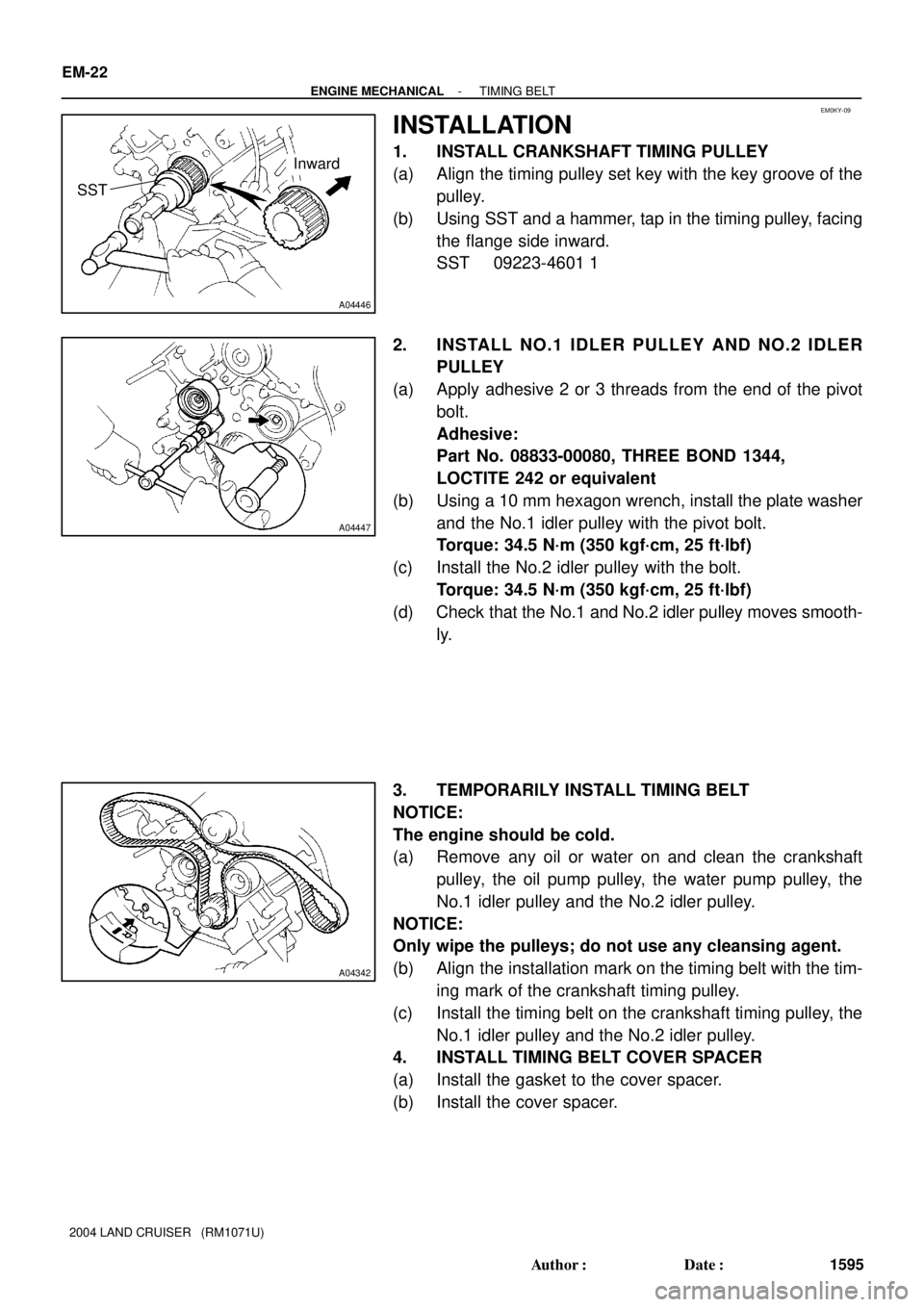
1. INSTALL CRANKSHAFT TIMING PULLEY
(a) Align the timing pulley set key with the key groove of the
pulley.
(b) Using SST and a hammer, tap in the timing pulley, facing
the flange side inward.
SST 09223-4601 1
2. INSTALL NO.1 IDLER PULLEY AND NO.2 IDLER
PULLEY
(a) Apply adhesive 2 or 3 threads from the end of the pivot
bolt.
Adhesive:
Part No. 08833-00080, THREE BOND 1344,
LOCTITE 242 or equivalent
(b) Using a 10 mm hexagon wrench, install the plate washer
and the No.1 idler pulley with the pivot bolt.
Torque: 34.5 N´m (350 kgf´cm, 25 ft´lbf)
(c) Install the No.2 idler pulley with the bolt.
Torque: 34.5 N´m (350 kgf´cm, 25 ft´lbf)
(d) Check that the No.1 and No.2 idler pulley moves smooth-
ly.
3. TEMPORARILY INSTALL TIMING BELT
NOTICE:
The engine should be cold.
(a) Remove any oil or water on and clean the crankshaft
pulley, the oil pump pulley, the water pump pulley, the
No.1 idler pulley and the No.2 idler pulley.
NOTICE:
Only wipe the pulleys; do not use any cleansing agent.
(b) Align the installation mark on the timing belt with the tim-
ing mark of the crankshaft timing pulley.
(c) Install the timing belt on the crankshaft timing pulley, the
No.1 idler pulley and the No.2 idler pulley.
4. INSTALL TIMING BELT COVER SPACER
(a) Install the gasket to the cover spacer.
(b) Install the cover spacer.