Page 1399 of 3115
P0230
(DI-162)
Fuel Pump Primary Circuit
�Open or short in fuel pump relay circuit
�Fuel pump relay
�Circuit opening relay
�F")
DI-40
- DIAGNOSTICSENGINE
233 Author�: Date�:
2004 LAND CRUISER (RM1071U)P0230
(DI-162)
Fuel Pump Primary Circuit
�Open or short in fuel pump relay circuit
�Fuel pump relay
�Circuit opening relay
�Fuel pump
�ECM
-�
P0300
(DI-167)Random/Multiple Cylinder Misfire
Detected�*2�
P0301
(DI-167)Cylinder 1 Misfire Detected
�Open or short in engine wire
�*2�
P0302
(DI-167)Cylinder 2 Misfire Detected
�Open or short in engine wire
�Connector connection
�Vacuum hose connection
�*2�
P0303
(DI-167)Cylinder 3 Misfire Detected
�Vacuum hose connection
�Ignition system
�Injector�*2�
P0304
(DI-167)Cylinder 4 Misfire Detected
�Fuel pressure
�Mass air flow meter
�Engine coolant temperature sensor
�*2�
P0305
(DI-167)Cylinder 5 Misfire Detected
�Engine coolant temperature sensor
�Compression pressure
�Valve clearance
�*2�
P0306
(DI-167)Cylinder 6 Misfire Detected
�Valve clearance
�Valve timing
�PCV piping�*2�
P0307
(DI-167)Cylinder 7 Misfire Detected
�ECM
�*2�
P0308
(DI-167)Cylinder 8 Misfire Detected�*2�
P0325
(DI-186)Knock Sensor 1 Circuit (Bank 1
or Single Sensor)�Open or short in knock sensor 1 circuit
�Knock sensor 1 (looseness)
�ECM
��
P0330
(DI-186)Knock Sensor 2 Circuit (Bank 2)
�Open or short in knock sensor 2 circuit
�Knock sensor 2 (looseness)
�ECM
��
P0335
(DI-191)Crankshaft Position Sensor ºAº
Circuit
�Open or short in crankshaft position sensor circuit
�Crankshaft position sensor
�Signal plate
�ECM
��
P0339
(DI-191)Crankshaft Position Sensor ºAº
Circuit Intermittent
�Open or short in crankshaft position sensor circuit
�Crankshaft position sensor
�Signal plate
�ECM
-�
P0340
(DI-197)Camshaft Position Sensor ºAº
Circuit (Bank 1 or Single Sensor)�Open or short in camshaft position sensor circuit
�Camshaft position sensor��
P0341
(DI-197)Camshaft Position Sensor ºAº
Circuit Range/Performance
(Bank 1 or Single Sensor)
�Camshaft osition sensor
�LH camshaft timing pulley
�Jumping teeth of timing belt
�ECM
��
P0351
(DI-202)Ignition Coil ºAº Primary/Second-
ary Circuit
�Open or short in IGF 1 and IGT 1 circuit from No. 1 ignition coil
with igniter to ECM
�No. 1 ignition coil with igniter
�Ignition system
�ECM
��
P0352
(DI-202)Ignition Coil ºBº Primary/Second-
ary Circuit
�Open or short in IGF 2 and IGT 2 circuit from No. 2 ignition coil
with igniter to ECM
�No. 2 ignition coil with igniter
�Ignition system
�ECM
��
Page 1797 of 3115

DISASSEMBLY
1. INSTALL ENGINE TO ENGINE")
EM0L6-03
A05112
Pull
Wire
Clamp
O-Ring
A05110
LH Side
A05109
RH Side EM-88
- ENGINE MECHANICALCYLINDER BLOCK
1661 Author�: Date�:
2004 LAND CRUISER (RM1071U)
DISASSEMBLY
1. INSTALL ENGINE TO ENGINE STAND
2. REMOVE TIMING BELT AND PULLEYS
(See page EM-15)
3. REMOVE CYLINDER HEAD (See page EM-35)
4. REMOVE WATER BYPASS PIPE
(a) Disconnect the wire clamp (for knock sensor 1, 2) from the
bracket of the water bypass pipe.
(b) Remove the bolt.
(c) Pull out the water bypass pipe from the water pump.
(d) Remove the O-ring from the water bypass pipe.
5. REMOVE STARTER (See page ST-5)
6. REMOVE KNOCK SENSORS (See page SF-55)
7. DISCONNECT ENGINE WIRE FROM LH SIDE OF CYL-
INDER BLOCK
(a) Remove the 2 bolts and the engine wire cover from the LH
side of the cylinder block.
(b) Remove the bolt, disconnect the bracket on the engine
wire from the cylinder block.
8. DISCONNECT ENGINE WIRE FROM RH SIDE OF CYL-
INDER BLOCK
Remove the 2 bolts, and disconnect the 2 brackets on the en-
gine wire from the cylinder block.
9. REMOVE OIL COOLER PIPE BRACKET FOR A/T
Remove the bolt and bracket.
10. REMOVE ENGINE MOUNTING BRACKETS
Remove the 4 bolts and the mounting bracket. Remove the 2
mounting brackets
11. REMOVE WATER PUMP (See page CO-6)
12. REMOVE NO.2 OIL PAN (See page LU-8)
13. REMOVE OIL PAN BAFFLE PLATE
14. REMOVE NO.1 OIL PAN (See page LU-8)
15. REMOVE OIL STRAINER
16. REMOVE OIL PUMP (See page LU-8)
17. REMOVE ENGINE COOLANT DRAIN UNIONS
Remove the 2 drain unions.
Page 1820 of 3115
EM-1 14
- ENGINE MECHANICALCYLINDER BLOCK
1687 Author�: Date�:
2004 LAND CRUISER (RM1071U)
30. INSTALL TIMING BELT AND PULLEYS
(See page EM-22)
31. DISCONNECT ENGINE FROM ENGINE STAND
Page 1826 of 3115
A04460
RH No. 3 Timing Belt Cover
No. 2 Timing
Belt Cover
LH No. 3 Timing Belt Cover Drive Belt Idler Pulley
Camshaft Position
Sensor ConnectorCover Plate
Engine Wire
16 (160, 12)
7.5 (80, 16 in.´lbf)
N´m (kgf´cm, ft´lbf) : Specified torque
Oil Cooler PipeWire Grommet
39 (400, 29)
7.5 (80, 66 in.´lbf)
Camshaft Position Sensor
A04327
Timing BeltRH Camshaft Timing Pulley
LH Camshaft Timing Belt Pulley
Timing Belt Tensioner
Fan BracketDust Boot
108 (1,100, 80)
245 (2,500, 181)
16 (160, 12)
32 (330, 24)26 (270, 19)N´m (kgf´cm, ft´lbf) : Specified torque
EM-30
- ENGINE MECHANICALCYLINDER HEAD
1603 Author�: Date�:
2004 LAND CRUISER (RM1071U)
Page 1827 of 3115
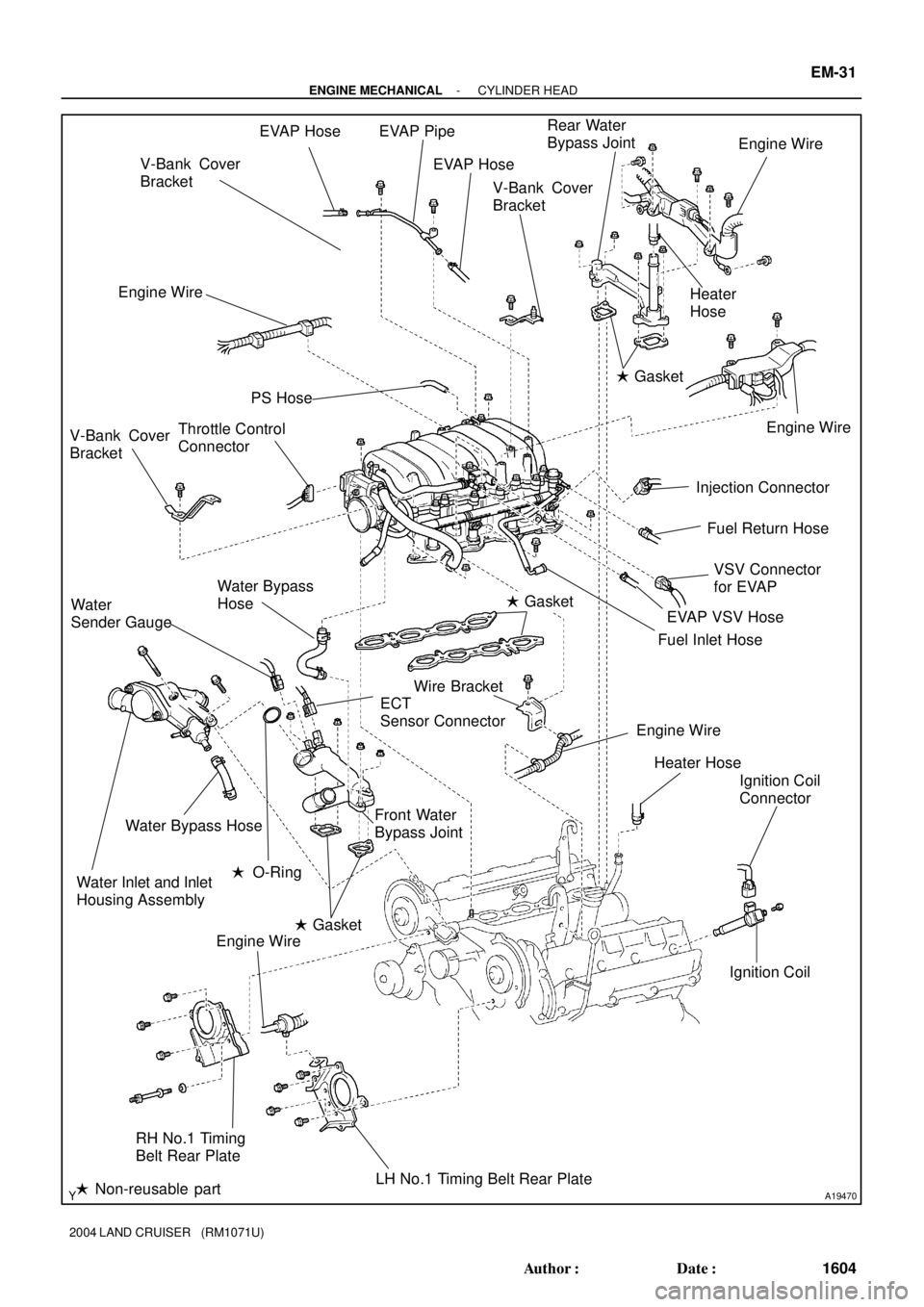
A19470
EVAP Hose EVAP PipeRear Water
Bypass Joint
Engine Wire
� Gasket
Injection Connector
Fuel Inlet Hose
Ignition Coil
Connector
Ignition Coil Throttle Control
Connector
Water Bypass
Hose
ECT
Sensor Connector
Front Water
Bypass Joint
Water Inlet and Inlet
Housing AssemblyWater Bypass Hose Water
Sender Gauge
LH No.1 Timing Belt Rear Plate
� Non-reusable partEngine WireEngine Wire
� Gasket
� O-Ring
RH No.1 Timing
Belt Rear PlateEVAP Hose
Engine Wire
� GasketHeater
Hose V-Bank Cover
Bracket
V-Bank Cover
BracketPS Hose
VSV Connector
for EVAP Fuel Return Hose
V-Bank Cover
Bracket
Engine Wire
EVAP VSV Hose
Heater Hose
Wire Bracket
- ENGINE MECHANICALCYLINDER HEAD
EM-31
1604 Author�: Date�:
2004 LAND CRUISER (RM1071U)
Page 1852 of 3115

(o)
(n)
(m)(r)
(q)
- ENGINE MECHANICALCYLINDER HEAD
EM-69
1642 Author�: Date�:
2004 LAND CRUISER (RM1071U)
(d) Install the EVAP pipe to the intake manifo")
A05514
A19472
A05562
B01208
A17668A19481
(p)
(o)
(n)
(m)(r)
(q)
- ENGINE MECHANICALCYLINDER HEAD
EM-69
1642 Author�: Date�:
2004 LAND CRUISER (RM1071U)
(d) Install the EVAP pipe to the intake manifold with the 2
bolts.
(e) Connect the wire protector to the intake manifold with the
2 bolts.
(f) Install the engine wire to the engine hanger.
(g) Install the engine wire to the LH No.1 timing belt rear
plate.
(h) Install the engine wire to the bracket.
(i) Connect the wire protector to the rear water bypass joint
and RH cylinder head with the 2 bolts.
(j) Install the 2 ground cables to the RH and LH cylinder
head.
(k) Install the guide for A/T bracket to the LH cylinder head.
(l) Connect the 2 wire clamps to the wire clamp bracket on
the RH delivery pipe.
(m) Connect the fuel pressure regulator vacuum hose to the
fuel pressure regulator pipe.
(n) Connect the PCV hose to the PCV valve on the LH cylin-
der head.
(o) Connect the EVAP hose (from charcoal canister) to the
VSV for EVAP.
(p) Connect the EVAP hose (from charcoal canister) to the
EVAP pipe on the intake manifold.
(q) Connect the EVAP hose (from intake air connector) to
EVAP pipe on the the intake manifold.
Page 1853 of 3115

(r) Connect the PS air hose to intake manifold.
(s) Connect the No.1 wat")
B15320B16469No. 1 Water Bypass Hose
EM-70
- ENGINE MECHANICALCYLINDER HEAD
1643 Author�: Date�:
2004 LAND CRUISER (RM1071U)
(r) Connect the PS air hose to intake manifold.
(s) Connect the No.1 water bypass hose (from water inlet
housing) to throttle body.
(t) Connect the throttle control connector.
(u) Connect the VSV connector for EVAP.
(v) Connect the 8 injector connectors.
(w) Connect the ECT sensor.
(x) Connect the water sender gauge.
(y) Connect the 8 ignition coil connectors.
(z) Connect the 2 oxygen sensor connectors.
19. CONNECT FUEL INLET HOSE (See page SF-24)
20. INSTALL TIMING BELT REAR PLATES
(a) Install the RH timing belt rear plates.
Install the No.1 timing belt rear plate to the cylinder head
with the 3 bolts and the stud bolt.
Torque: 7.5 N´m (80 kgf´cm, 66 in.´lbf)
(b) Install the LH timing belt rear plates.
(1) Connect the wire clamp to the No.1 timing belt rear
plate.
(2) Install the No.1 timing belt rear plate to the cylinder
head with the 3 bolts.
Torque: 7.5 N´m (80 kgf´cm, 66 in.´lbf)
21. INSTALL V-BANK COVER
Install the 3 V-bank covers.
Torque: 7.5 N´m (80 kgf´cm, 66 in.´lbf)
22. INSTALL IGNITION COILS (See page IG-6)
23. INSTALL OIL DIPSTICK AND GUIDE FOR A/T
24. INSTALL FRONT EXHAUST PIPE (See page EM-1 15)
25. INSTALL PS PUMP (See page EM-81)
26. INSTALL CAMSHAFT POSITION SENSOR (See page
IG-10)
27. INSTALL CAMSHAFT TIMING PULLEYS
(See page EM-22)
28. CONNECT TIMING BELT TO CAMSHAFT TIMING PUL-
LEYS (See page EM-22)
29. CHECK ENGINE OIL LEVEL
Page 1856 of 3115

REMOVAL
1. DRAIN ENGINE COOLANT
2. REMOVE V-BANK COVER
Remove the V-bank covers.
3. DISCONNECT")
EM1V8-01
A02844
- ENGINE MECHANICALCYLINDER HEAD
EM-35
1608 Author�: Date�:
2004 LAND CRUISER (RM1071U)
REMOVAL
1. DRAIN ENGINE COOLANT
2. REMOVE V-BANK COVER
Remove the V-bank covers.
3. DISCONNECT TIMING BELT FROM CAMSHAFT TIM-
ING PULLEYS (See page EM-15)
4. REMOVE CAMSHAFT TIMING PULLEYS (See page
EM-15)
5. REMOVE CAMSHAFT POSITION SENSOR (See page
IG-9)
6. DISCONNECT PS PUMP FROM ENGINE
(See page EM-77)
7. REMOVE FRONT EXHAUST PIPE (See page EM-1 15)
8. REMOVE OIL DIPSTICK AND GUIDE FOR A/T
9. REMOVE IGNITION COILS (See page IG-6)
10. REMOVE TIMING BELT REAR PLATES
(1) Remove the 3 bolts, the stud bolt, and the RH No.1
timing belt rear plates.
(2) Disconnect the wire clamp from the LH timing belt
rear plate.
(3) Remove the 3 bolts, the stud bolt, the LH No.1 and
the timing belt rear plates.
NOTICE:
�Be careful not to drop anything inside the timing belt
cover.
�Do not allow the belt to contact correct with oil, water
or dust.
11. DISCONNECT FUEL INLET HOSE (See page SF-24)
12. REMOVE INTAKE MANIFOLD ASSEMBLY
(a) Disconnect the throttle control connector.
(b) Disconnect the VSV connector for EVAP.
(c) Disconnect the 8 injector connectors.
(d) Disconnect the ECT sensor connector.
(e) Disconnect the water sender gauge connector.
(f) Disconnect the 8 ignition coil connectors.
(g) Disconnect the 2 oxygen sensor connectors.


7.5 (80, 16 in.´lbf")