Page 758 of 3115
B04470
RH No.3 Timing Belt Cover
LH No.3 Timing Belt CoverNo.2 Timing Belt Cover
Camshaft Position
Sensor Connector
Engine Wire
Oil Cooler Pipe
Timing Belt
Fan Bracket Drive Belt Timing Pulley
Timing Belt Tensioner Dust Boot
N´m (kgf´cm, ft´lbf) : Specified torqueCover Plate
7.5 (80, 66 in.´lbf)
16 (160, 12)
39 (400,29)
245 (2,500, 181)
32 (330, 24)
16 (160, 12)
7.5 (80, 66 in.´lbf)
Water Bypass
Hose
CO-4
- COOLINGWATER PUMP
1765 Author�: Date�:
2004 LAND CRUISER (RM1071U)
Page 759 of 3115
B04471
Generator Wire
Generator Connector
Wire Clamp
Generator
Crankshaft PulleyDrive Belt Tensioner
No.1 Timing Belt Cover
Timing Belt
Timing Belt Guide
(Crankshaft Angle Sensor Plate)No.2 Idler Pulley
Timing Belt Cover SpacerGasket
N´m (kgf´cm, ft´lbf) : Specified torque
� Non-reusable partWater Inlet Housing
Assembly
Water Pump � O-Ring
� Gasket � O-Ring
39 (400, 29)
34.5 (350, 25)
18 (185, 13)
21 (215, 15)
- COOLINGWATER PUMP
CO-5
1766 Author�: Date�:
2004 LAND CRUISER (RM1071U)
Page 760 of 3115
CO0IS-01
B04067Air HoleWa t e r
Hole
- COOLINGWATER PUMP
CO-7
1768 Author�: Date�:
2004 LAND CRUISER (RM1071U)
INSPECTION
1. INSPECT WATER PUMP
(a) Visually check the air hole and water hole for coolant leak-
age.
If leakage is found, replace the water pump and timing belt.
(b) Turn the pulley, and check that the water pump bearing
moves smoothly and quietly.
If necessary, replace the water pump.
2. INSPECT TIMING BELT COMPONENTS
(See page EM-20)
Page 762 of 3115
B04460
AB
- COOLINGWATER PUMP
CO-9
1770 Author�: Date�:
2004 LAND CRUISER (RM1071U)
(f) Install the water inlet and housing assembly with the 2
bolts. Alternately tighten the bolts.
Torque: 18 N´m (185 kgf´cm, 13 ft´lbf)
HINT:
Each bolt length is indicated in the illustration.
Bolt length:
76 mm (3.00 in.) for A
22 mm (0.87 in.) for B
3. INSTALL NO.2 IDLER PULLEY (See page EM-22)
4. INSTALL TIMING BELT (See page EM-22)
5. FILL WITH ENGINE COOLANT
6. START ENGINE AND CHECK FOR ENGINE COOLANT
LEAKS
7. RECHECK ENGINE COOLANT LEVEL
Page 763 of 3115
CO0IR-01
B04460
B04461
CO-6
- COOLINGWATER PUMP
1767 Author�: Date�:
2004 LAND CRUISER (RM1071U)
REMOVAL
1. DRAIN ENGINE COOLANT
2. REMOVE TIMING BELT (See page EM-15)
3. REMOVE NO.2 IDLER PULLEY (See page EM-15)
4. REMOVE WATER INLET AND INLET HOUSING AS-
SEMBLY
(a) Disconnect the water bypass hose from the water inlet
housing.
(b) Remove the 2 bolts holding the water inlet housing to the
water pump.
(c) Disconnect the water inlet housing from the front water
bypass joint, and remove the water inlet and inlet housing
assembly.
(d) Remove the O-ring from the water inlet housing.
5. REMOVE WATER PUMP
(a) Remove the 5 bolts, 2 stud bolts, nut, water pump and
gasket.
(b) Remove the O-ring from the water bypass pipe.
Page 1232 of 3115
- DIAGNOSTICSENGINE
DI-183
376 Author�: Date�:
2004 LAND CRUISER (RM1071U)
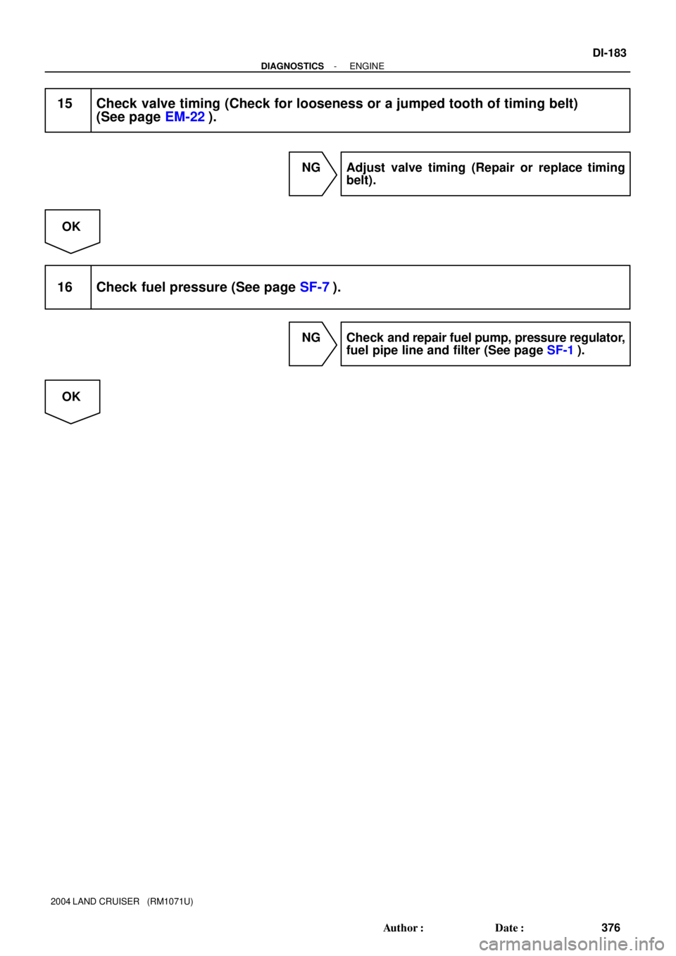
15 Check valve timing (Check for looseness or a jumped tooth of timing belt)
(See page EM-22).
NG Adjust valve timing (Repair or replace timing
belt).
OK
16 Check fuel pressure (See page SF-7).
NG Check and repair fuel pump, pressure regulator,
fuel pipe line and filter (See page SF-1).
OK
Page 1246 of 3115

10 msec./Division (Idling)5 V
/Division
G2
NE
5 V
/Division
G2
NE
- DIAGNOSTICSENGINE
DI-197
390 Author�: Date�:
2004 LAND CRU")
FI7059
FI7060A00069
G2 and NE Signal Waveforms
20 msec./Division (Idling)
10 msec./Division (Idling)5 V
/Division
G2
NE
5 V
/Division
G2
NE
- DIAGNOSTICSENGINE
DI-197
390 Author�: Date�:
2004 LAND CRUISER (RM1071U)
DTC P0340 Camshaft Position Sensor ºAº Circuit
(Bank 1 or Single Sensor)
DTC P0341 Camshaft Position Sensor ºAº Circuit
Range/Performance (Single Sensor)
CIRCUIT DESCRIPTION
The camshaft position sensor (G signal) consists of a magnet iron core and pickup coil.
The G signal plate has 1 tooth on its outer circumference and is installed on the LH camshaft timing pulley.
When the camshafts rotate, protrusion on the signal plate and air gap on the pickup coil change, causing
fluctuations in the magnetic field and generating a voltage in the pickup coil.
The NE signal plate has 34 teeth and is mounted on the crankshaft. The NE signal sensor generates 34
signals at every engine revolution. The ECM detects the crankshaft angle and the engine revolution based
on the NE signals, and the cylinder and the angle of the G2 based on the combination of the G and NE sig-
nals.
DTC No.DTC Detection ConditionTrouble Area
P0340
No camshaft position sensor signal to ECM during cranking
(2 trip detection logic)
P0340No camshaft position sensor signal to ECM with engine
speed 600 rpm or more (1 trip detection logic)�Open or short in camshaft position sensor circuit
�Camshaftposition sensor
P0341
While crankshaft rotates twice, camshaft position sensor
signal will be input to ECM 12 times or more (1 trip detec-
tion logic)
�Hint:
Under normal condition, the camshaft position signal is
input into the ECM 3 times per 2 engine revolutions�Camshaft position sensor
�LH camshaft timing pulley
�Jumping teeth of timing belt
�ECM
Reference: Inspection using the oscilloscope.
The correct waveform is as shown.
Tester ConnectionSpecified Condition
G2+ (E7-27) - G2- (E7-32)Ct fi hNE+ (E7-25) - NE- (E7-24)Correct waveform is as shown
DIC2E-01
Page 1250 of 3115
- DIAGNOSTICSENGINE
DI-201
394 Author�: Date�:
2004 LAND CRUISER (RM1071U)
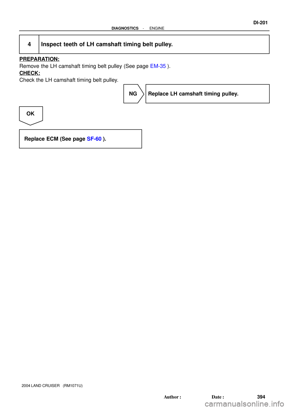
4 Inspect teeth of LH camshaft timing belt pulley.
PREPARATION:
Remove the LH camshaft timing belt pulley (See page EM-35).
CHECK:
Check the LH camshaft timing belt pulley.
NG Replace LH camshaft timing pulley.
OK
Replace ECM (See page SF-60).

No.2 Idler Pull")