Page 386 of 3115

BO1KT-04
H18928
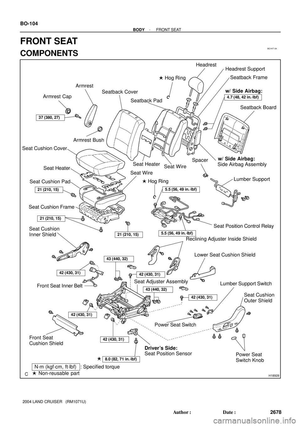
Headrest
Headrest Support
Seatback Board
Lumber Support Seatback Frame
Seatback Pad Armrest
Seat Cushion Cover
Seat Cushion Pad
Seat Cushion Frame
Seat Cushion
Inner Shield
Front Seat Inner BeltReclining Adjuster Inside Shield
Lower Seat Cushion Shield
Seat Cushion
Outer Shield
Power Seat
Switch Knob Power Seat SwitchLumber Support Switch
Front Seat
Cushion ShieldSeat Position Control Relay Seatback Cover� Hog Ring
� Hog Ring
: Specified torqueN´m (kgf´cm, ft´lbf)
� Non-reusable part
Seat HeaterSeat Heater
Seat WireSeat Wire
Seat Adjuster Assembly
w/ Side Airbag:
Side Airbag Assembly
37 (380, 27)
21 (210, 15)
21 (210, 15)
43 (440, 32)
21 (210, 15)
42 (430, 31)
8.0 (82, 71 in.´lbf)
Seat Position Sensor Driver's Side:
42 (430, 31)
�
42 (430, 31)
42 (430, 31)
Armrest Cap
Armrest Bush
Spacer
4.7 (48, 42 in.´lbf)
w/ Side Airbag:
5.5 (56, 49 in.´lbf)
5.5 (56, 49 in.´lbf)
42 (430, 31)
43 (440, 32)
BO-104
- BODYFRONT SEAT
2678 Author�: Date�:
2004 LAND CRUISER (RM1071U)
FRONT SEAT
COMPONENTS
Page 387 of 3115
BO4J1-01
H03731
A
B
H03732
H03733
H03734
BO-106
- BODYFRONT SEAT
2680 Author�: Date�:
2004 LAND CRUISER (RM1071U)
DISASSEMBLY
1. REMOVE HEADREST
2. REMOVE SEATBACK BOARD
Remove the seatback board as shown in the illustration.
HINT:
Remove the seatback board in the order of ºAº and ºBº as
shown in the illustration.
3. REMOVE SEAT CUSHION OUTER SHIELD
(a) Using a screwdriver, remove the power seat switch
knobs.
HINT:
Tape up the screwdriver tip before use.
(b) Remove the 4 screws.
(c) Disconnect the connectors as shown in the illustration.
(d) Remove the seat cushion outer shield.
(e) Remove the 3 screws and the power seat switch from the
seat cushion outer shield.
(f) Remove the 2 screws and lumber support switch from the
seat cushion outer shield.
Page 389 of 3115

H20963
H19941
H21292
H20961
BO-108
- BODYFRONT SEAT
2682 Author�: Date�:
2004 LAND CRUISER (RM1071U)
12. REMOVE SEATBACK ASSEMBLY
(a) Remove the hog rings.
(b) Disengage the hook as shown in the illustration.
(c) Disconnect the connectors.
(d) Remove the 4 bolts and the seatback assembly.
NOTICE:
When handling the airbag connector take care not to dam-
age the airbag wire harness.
(e) Remove the screw and the RH reclining adjuster inside
shield.
(f) w/ Side Airbag:
Disconnect the side airbag connector.
NOTICE:
When handling the airbag connector take care not to dam-
age the airbag wire harness.
(g) Remove the screw and the LH reclining adjuster inside
shield.
13. REMOVE ARMREST
14. w/o Side Airbag:
REMOVE SEATBACK FRAME
(a) Remove the hog rings.
(b) Remove the 2 headrest supports.
(c) Remove the seatback frame from the seatback cover with
pad.
15. w/ Side Airbag:
REMOVE SEATBACK FRAME
(a) Remove the hog rings, the clamps and the 2 bolts.
(b) Remove the 2 headrest supports.
(c) Remove the seatback frame from the seatback cover with
pad.
Page 392 of 3115
BO4J3-01
H18929
H04785
H04468
H21292
BO-1 14
- BODYFRONT SEAT
2688 Author�: Date�:
2004 LAND CRUISER (RM1071U)
REASSEMBLY
1. Driver 's Side:
INSTALL SEAT POSITION SENSOR
Install the seat position sensor with a new bolt, then connect the
connector.
Part No.:
Bolt: 90119-06871
Torque: 8.0 N´m (82 kgf´cm, 71 in.´lbf)
2. INSTALL SEAT POSITION CONTROL RELAY
Install the seat position control relay with the 2 bolts, then con-
nect the connectors.
Torque: 5.5 N´m (56 kgf´cm, 49 in.´lbf)
3. INSTALL SEATBACK COVER
Install the seatback cover to the seatback pad with new hog
rings.
4. INSTALL LUMBER SUPPORT
Install the lumber support and the spacer with the 2 bolts.
5. w/o Side Airbag:
INSTALL SEATBACK FRAME
(a) Install the seatback cover to the seatback frame.
(b) Install new hog rings.
(c) Install the 2 headrest supports.
Page 393 of 3115

H20961
H21294
H19941
H21291
H20959
- BODYFRONT SEAT
BO-1 15
2689 Author�: Date�:
2004 LAND CRUISER (RM1071U)
6. w/ Side Airbag:
INSTALL SEATBACK FRAME
(a) Install the seatback cover to the seatback frame.
(b) Install new hog rings, the clamps and the 2 bolts.
Torque: 4.7 N´m (48 kgf´cm, 42 in.´lbf)
(c) Install the 2 headrest supports.
7. INSTALL SEATBACK ASSEMBLY
(a) w/o Side Airbag:
Install the RH reclining adjuster inside shield with a screw.
(b) w/ Side Airbag:
Place the airbag connector along the inner seat adjuster,
and then install the RH reclining adjuster inside shield
with a screw so that the connector is placed in between.
NOTICE:
When handling the airbag connector, take care not to dam-
age the airbag wire harness.
(c) Install the LH reclining adjuster inside shield with a screw.
(d) Install the seatback assembly with the 4 bolts.
Torque: 43 N´m (440 kgf´cm, 32 ft´lbf)
(e) Install new hog rings.
(f) Hang the hook.
(g) Connect the connectors.
8. INSTALL ARMREST
Torque: 37 N´m (380 kgf´cm, 27 ft´lbf)
9. INSTALL HEADREST
10. INSTALL SEAT CUSHION COVER (See page BO-1 10)
11. INSTALL SEAT CUSHION FRAME
(a) Install the seat cushion frame with new hog rings to the
seat cushion cover with pad.
(b) Hang the hook.
12. INSTALL SEAT CUSHION ASSEMBLY
(a) Install the seat cushion assembly with the 4 bolts to the
seat adjuster.
Torque: 21 N´m (210 kgf´cm, 15 ft´lbf)
(b) Engage the wire harness clamp.
Page 446 of 3115

BO1L0-05
H16046
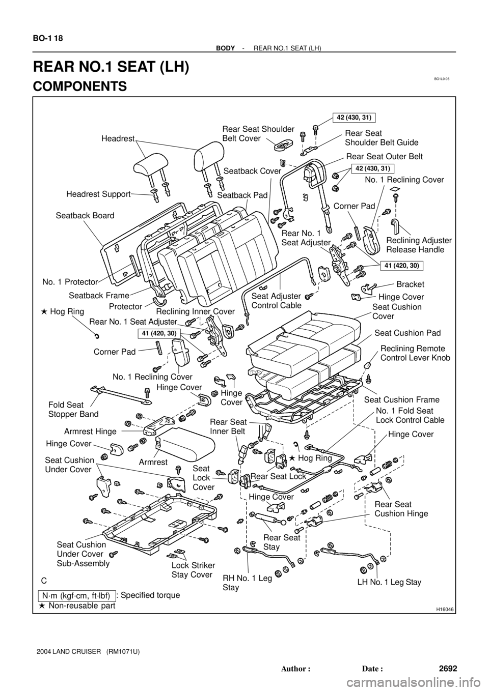
Headrest
Headrest SupportRear Seat Shoulder
Belt CoverRear Seat
Shoulder Belt Guide
Rear Seat Outer Belt
Reclining Adjuster
Release Handle No. 1 Reclining Cover
Corner Pad
Rear No. 1
Seat Adjuster
Seat Adjuster
Control Cable Seatback Cover
Seatback Pad
Seatback Frame No. 1 ProtectorSeatback Board
Protector
Rear No. 1 Seat AdjusterReclining Inner Cover
Corner Pad
No. 1 Reclining Cover
Hinge
CoverSeat Cushion
Cover
Seat Cushion Pad
Seat Cushion FrameReclining Remote
Control Lever Knob
Hinge Cover
Fold Seat
Stopper Band
Armrest Seat Cushion
Under Cover
Lock Striker
Stay Cover
RH No. 1 Leg
StayLH No. 1 Leg Stay Rear Seat
StayRear Seat
Cushion HingeHinge Cover
Hinge CoverNo. 1 Fold Seat
Lock Control Cable
Seat
Lock
CoverRear Seat
Inner Belt
: Specified torque
� Non-reusable part� Hog Ring
� Hog Ring
42 (430, 31)
Armrest Hinge
Hinge Cover
41 (420, 30)
Hinge Cover
Rear Seat Lock
Bracket
Seat Cushion
Under Cover
Sub-Assembly
42 (430, 31)
C
41 (420, 30)
N´m (kgf´cm, ft´lbf) BO-1 18
- BODYREAR NO.1 SEAT (LH)
2692 Author�: Date�:
2004 LAND CRUISER (RM1071U)
REAR NO.1 SEAT (LH)
COMPONENTS
Page 447 of 3115

BO1L2-06
H05322
H05304
H05308
BO-120
- BODYREAR NO.1 SEAT (LH)
2694 Author�: Date�:
2004 LAND CRUISER (RM1071U)
DISASSEMBLY
1. REMOVE HEADRESTS
2. REMOVE SEATBACK BOARD
Using a screwdriver, remove the seatback board as shown in
the illustration.
HINT:
Tape the screwdriver tip before use.
3. REMOVE RECLINING ADJUSTER RELEASE HANDLE
(a) Using a screwdriver, remove the cover.
HINT:
Tape the screwdriver tip before use.
(b) Remove the screw and reclining adjuster release handle.
4. REMOVE NO. 1 RECLINING COVERS
(a) Remove the 4 hog rings and open the seatback cover.
HINT:
At the time of reassembly, please refer to the following item.
When installing hog rings, take care to prevent wrinkles as little
as possible.
(b) Remove the 2 corner pads.
(c) Remove the 2 screws and 2 No. 1 reclining covers as
shown in the illustration.
5. REMOVE SEAT CUSHION UNDER COVERS
Remove the 2 screws and 2 seat cushion under covers.
6. REMOVE SEAT CUSHION UNDER COVER SUB-AS-
SEMBLY
(a) Using a screwdriver, disengage the hooks as shown in the
illustration.
HINT:
Tape the screwdriver tip before use.
Page 449 of 3115

H05730
A
H05325
H05326
H05327
H05331
BO-122
- BODYREAR NO.1 SEAT (LH)
2696 Author�: Date�:
2004 LAND CRUISER (RM1071U)
HINT:
At the time of reassembly, please refer to the following items.
�Tighten the 2 screws on the seatback side.
�Fold down the seatback forward and raise it up to the first
lock position.
�Turn A to the rear side of the seat cushion for initial posi-
tioning.
�Check visually that the reference holes are penetrated.
�Tighten the screws on the cushion side of seat belt reclin-
ing detecting part.
(b) Loosen the nut, remove the reclining connecting wire of
LH side edge.
(c) Remove the reclining connecting wire of RH side edge.
(d) Remove the 4 bolts and seatback assembly.
Torque: 41 N´m (420 kgf´cm, 30 ft´lbf)
11. w/ Armrest:
REMOVE ARMREST
(a) Remove the 2 nuts and armrest.
(b) Remove the 2 screws and 2 hinge covers.
(c) Remove the 2 bolts and hinges.
12. REMOVE SEATBACK FRAME
(a) Using a screwdriver, remove the rear seat shoulder belt
cover.
HINT:
Tape the screwdriver tip before use.
(b) Remove the 4 headrest supports.
(c) Disengage the hooks, remove the seatback frame.
13. REMOVE SEAT ADJUSTER CONTROL CABLE