Page 37 of 3115

I06740
AC1LH-03
N17641
12 345
- AIR CONDITIONINGBLOWER MOTOR CONTROL RELAY
AC-81
2806 Author�: Date�:
2004 LAND CRUISER (RM1071U)
BLOWER MOTOR CONTROL
RELAY
INSPECTION
1. REMOVE BLOWER MOTOR CONTROL RELAY
(a) Disconnect the connectors.
(b) Remove the screw and the blower motor control relay.
2. INSPECT BLOWER MOTOR CONTROL RELAY
Connect the connector to the blower motor control relay and in-
spect the wire harness side connector from the back side as
shown in the illustration.
Test condition:
�Turn ignition switch to ON
Tester connectionConditionSpecified condition
1 - GroundConstantContinuity
2G dBlower speed control switch at ºLOº positionApprox. 3.5 V2 - GroundBlower speed control switch at ºM1º positionApprox. 2.2 V
3G dOperate blower motorBattery positive voltage3 - GroundBlower speed control switch at ºOFFº positionNo voltage
Blower speed control switch at ºLOº positionApprox. 3.6 V
4 - 5Blower speed control switch at ºM2º positionApprox. 8.3 V4 5
Blower speed control switch at ºHIº positionApprox. 13.0 V
If circuit is not as specified, replace the relay.
Page 38 of 3115

I06740
AC1LH-03
N17641
12 345
- AIR CONDITIONINGBLOWER MOTOR CONTROL RELAY
AC-81
2806 Author�: Date�:
2004 LAND CRUISER (RM1071U)
BLOWER MOTOR CONTROL
RELAY
INSPECTION
1. REMOVE BLOWER MOTOR CONTROL RELAY
(a) Disconnect the connectors.
(b) Remove the screw and the blower motor control relay.
2. INSPECT BLOWER MOTOR CONTROL RELAY
Connect the connector to the blower motor control relay and in-
spect the wire harness side connector from the back side as
shown in the illustration.
Test condition:
�Turn ignition switch to ON
Tester connectionConditionSpecified condition
1 - GroundConstantContinuity
2G dBlower speed control switch at ºLOº positionApprox. 3.5 V2 - GroundBlower speed control switch at ºM1º positionApprox. 2.2 V
3G dOperate blower motorBattery positive voltage3 - GroundBlower speed control switch at ºOFFº positionNo voltage
Blower speed control switch at ºLOº positionApprox. 3.6 V
4 - 5Blower speed control switch at ºM2º positionApprox. 8.3 V4 5
Blower speed control switch at ºHIº positionApprox. 13.0 V
If circuit is not as specified, replace the relay.
Page 75 of 3115
I25155
AC3OX-01
N02832
3
2 1
5 4
1
43
25
AC-94
- AIR CONDITIONINGHEATER MAIN RELAY
2819 Author�: Date�:
2004 LAND CRUISER (RM1071U)
HEATER MAIN RELAY
INSPECTION
1. REMOVE HEATER MAIN RELAY
Remove the heater main relay.
2. INSPECT HEATER MAIN RELAY CONTINUITY
ConditionTester connectionSpecified condition
Constant1 - 2
3 - 4Continuity
Apply B+ between
terminals 1 and 2.3 - 5Continuity
If continuity is not as specified, replace the relay.
3. INSTALL HEATER MAIN RELAY
Page 76 of 3115
I25040
Relay BlockJunction Block
(Built-in Relay)AC1LY-03
I25183
Engine Room J/B
63
65
57 AC-96
- AIR CONDITIONINGMAGNETIC CLUTCH RELAY
2821 Author�: Date�:
2004 LAND CRUISER (RM1071U)
MAGNETIC CLUTCH RELAY
INSPECTION
HINT:
The magnetic clutch relay is built in the engine room junction
block. Since the relay is constructed with a relay block that is in
the junction block as a unit, it is impossible to disconnect the
wire harness connecting with the relay block.
If the relay has a malfunction, replace it with the junction block
assembly wire harness together.
1. REMOVE ENGINE ROOM J/B
2. INSPECT MAGNETIC CLUTCH RELAY CONTINUITY
ConditionTester connectionSpecified condition
Constant57 - 65Continuity
Apply B+ between
terminals 57 and 65.63 - 65Continuity
If continuity is not as specified, replace the engine room J/B.
3. INSTALL ENGINE ROOM J/B
Page 101 of 3115
I25040
Relay BlockJunction Block
(Built-in Relay)
AC3OY-01
I25183
Engine Room J/B
31 29 3 2
- AIR CONDITIONINGREAR HEATER RELAY
AC-95
2820 Author�: Date�:
2004 LAND CRUISER (RM1071U)
REAR HEATER RELAY
INSPECTION
HINT:
The rear heater relay is built in the engine room junction block.
Since the relay is constructed with a relay block that is in the
junction block as a unit, it is impossible to disconnect the wire
harness connecting with the relay block.
If the relay has a malfunction, replace it with the junction block
assembly wire harness together.
1. REMOVE ENGINE ROOM J/B
2. INSPECT REAR HEATER RELAY CONTINUITY
ConditionTester connectionSpecified condition
Constant29 - 31Continuity
Apply B+ between
terminals 29 and 31.2 - 3Continuity
If continuity is not as specified, replace the engine room J/B.
3. INSTALL ENGINE ROOM J/B
Page 227 of 3115

BE2EE-01
I25790
w/o Navigation System:
w/ Navigation System:
ABC
I01200
2 1
35
2 5
1 3
- BODY ELECTRICALDEFOGGER SYSTEM
BE-75
2448 Author�: Date�:
2004 LAND CRUISER (RM1071U)
INSPECTION
1. INSPECT DEFOGGER SWITCH CIRCUIT
Disconnect the connector from the panel switch and inspect the
connector on wire harness side, as shown in the chart.
w/ Navigation:
Tester connectionConditionSpecified condition
B12 (GND) - GroundConstantContinuity
B11 (+B) - GroundConstantBattery positive voltage
B22 (IG) - GroundIgnition switch LOCK or ACCNo voltage
B22 (IG) - GroundIgnition switch ONBattery positive voltage
A10 (RDFGR) - GroundConstantBattery positive voltage
w/o Navigation:
Tester connectionConditionSpecified condition
16 (GND) - GroundConstantContinuity
8 (IG) - GroundIgnition switch LOCK or ACCNo voltage
8 (IG) - GroundIgnition switch ONBattery positive voltage
2 (DEFC) - GroundConstantBattery positive voltage
If the circuit is not as specified, replace the switch.
2. INSPECT DEFOGGER RELAY CONTINUITY
ConditionTester connectionSpecified condition
Constant1 - 2Continuity
Apply B+ between
terminals 1 and 2.3 - 5Continuity
If continuity is not as specified, replace the relay.
Page 231 of 3115

BE2EE-01
I25790
w/o Navigation System:
w/ Navigation System:
ABC
I01200
2 1
35
2 5
1 3
- BODY ELECTRICALDEFOGGER SYSTEM
BE-75
2448 Author�: Date�:
2004 LAND CRUISER (RM1071U)
INSPECTION
1. INSPECT DEFOGGER SWITCH CIRCUIT
Disconnect the connector from the panel switch and inspect the
connector on wire harness side, as shown in the chart.
w/ Navigation:
Tester connectionConditionSpecified condition
B12 (GND) - GroundConstantContinuity
B11 (+B) - GroundConstantBattery positive voltage
B22 (IG) - GroundIgnition switch LOCK or ACCNo voltage
B22 (IG) - GroundIgnition switch ONBattery positive voltage
A10 (RDFGR) - GroundConstantBattery positive voltage
w/o Navigation:
Tester connectionConditionSpecified condition
16 (GND) - GroundConstantContinuity
8 (IG) - GroundIgnition switch LOCK or ACCNo voltage
8 (IG) - GroundIgnition switch ONBattery positive voltage
2 (DEFC) - GroundConstantBattery positive voltage
If the circuit is not as specified, replace the switch.
2. INSPECT DEFOGGER RELAY CONTINUITY
ConditionTester connectionSpecified condition
Constant1 - 2Continuity
Apply B+ between
terminals 1 and 2.3 - 5Continuity
If continuity is not as specified, replace the relay.
Page 242 of 3115
BE0RT-04
I06374
ON
OFF
I25040
Built in relayExcept built in relay
- BODY ELECTRICALFOG LIGHT SYSTEM
BE-37
2410 Author�: Date�:
2004 LAND CRUISER (RM1071U)
INSPECTION
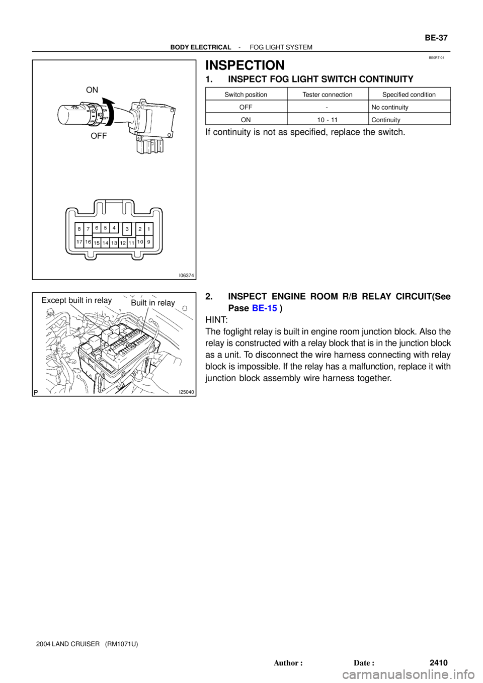
1. INSPECT FOG LIGHT SWITCH CONTINUITY
Switch positionTester connectionSpecified condition
OFF-No continuity
ON10 - 11Continuity
If continuity is not as specified, replace the switch.
2. INSPECT ENGINE ROOM R/B RELAY CIRCUIT(See
Pase BE-15)
HINT:
The foglight relay is built in engine room junction block. Also the
relay is constructed with a relay block that is in the junction block
as a unit. To disconnect the wire harness connecting with relay
block is impossible. If the relay has a malfunction, replace it with
junction block assembly wire harness together.