Page 1892 of 3115

5. INSTALL TIMING BELT GUIDE
Install the belt guide, facing the cup side out")
A04448
A04449
SST
A08660
A04340
SST
- ENGINE MECHANICALTIMING BELT
EM-23
1596 Author�: Date�:
2004 LAND CRUISER (RM1071U)
5. INSTALL TIMING BELT GUIDE
Install the belt guide, facing the cup side outward.
6. INSTALL NO.1 TIMING BELT COVER
Install the timing belt cover with the 4 bolts.
7. INSTALL CRANKSHAFT PULLEY
(a) Align the pulley set key with the key groove of the crank-
shaft pulley.
(b) Using SST and a hammer, tap in the crankshaft pulley.
SST 09223-4601 1
8. INSTALL DRIVE BELT TENSIONER
Install the belt tensioner with the bolt and the 2 nuts.
Torque: 16 N´m (160 kgf´cm, 12 ft´lbf)
HINT:
Use a bolt of 106 mm (4.18 in.) in length.
9. INSTALL GENERATOR
(See page CH-16)
10. CHECK CRANKSHAFT PULLEY POSITION
Check that the timing mark of the crankshaft pulley is aligned
with the timing mark º0º of the No.1 timing belt cover.
11. INSTALL RH, LH CAMSHAFT TIMING PULLEYS
(a) Align the camshaft knock pin with the knock pin grove of
the timing pulley, and slide on the timing pulley.
(b) Using SST, install the pulley bolt.
SST 09960-10010 (09962-01000, 09963-01000)
Torque: 108 N´m (1,100 kgf´cm, 80 ft´lbf)
Page 1893 of 3115

12. CONN")
A04451
Turn
A04452
Tension
Turn
A04453
Turn
P20636
1.27 mm
Hexagon
Wrench
A04454
1.27 mm
Hexagon
Wrench
EM-24
- ENGINE MECHANICALTIMING BELT
1597 Author�: Date�:
2004 LAND CRUISER (RM1071U)
12. CONNECT TIMING BELT TO LH CAMSHAFT
TIMING PULLEY
(a) Remove any oil or water on the LH camshaft timing pulley,
and clean it up.
NOTICE:
Only wipe the pulleys; do not use any cleansing agent.
(b) Turn the LH camshaft timing pulley. Align the installation
mark on the timing belt with the timing mark of the cam-
shaft timing pulley, and hang the timing belt on the LH
camshaft timing pulley.
(c) Turn the LH camshaft timing pulley counterclockwise until
there is tension between the crankshaft timing pulley and
the LH camshaft timing pulley.
13. CONNECT TIMING BELT TO RH CAMSHAFT
TIMING PULLEY
(a) Remove any oil or water on the RH camshaft timing pulley
and water pump pulley, and clean them up.
NOTICE:
Only wipe the pulleys; do not use any cleansing agent.
(b) Turn the RH camshaft timing pulley. Align the installation
mark on the timing belt with the timing mark of the cam-
shaft timing pulley, and hang the timing belt on the RH
camshaft timing pulley.
14. SET TIMING BELT TENSIONER
(a) Using a press, slowly press in the push rod using 981 -
9,807 N (100 - 1,000 kgf, 220 - 2,205 lbf) of pressure.
(b) Align the holes of the push rod and the housing, pass a
1.27 mm (0.050 in.) hexagon wrench through the holes to
keep the setting position of the push rod.
(c) Release the press.
(d) Install the dust boot to the belt tensioner.
15. INSTALL TIMING BELT TENSIONER
(a) Temporarily install the belt tensioner with the 2 bolts.
(b) Alternately tighten the 2 bolts.
Torque: 26 N´m (270 kgf´cm, 19 ft´lbf)
(c) Using pliers, remove the 1.27 mm (0.050 in.) hexagon
wrench from the belt tensioner.
Page 1894 of 3115
A08597Turn
A04335
A09156
SST
A04455
- ENGINE MECHANICALTIMING BELT
EM-25
1598 Author�: Date�:
2004 LAND CRUISER (RM1071U)
16. CHECK VALVE TIMING
(a) Temporarily install the crankshaft pulley bolt.
(b) Slowly turn the crankshaft pulley 2 revolutions from TDC
to TDC.
NOTICE:
Always turn the crankshaft pulley clockwise.
(c) Check that each pulley aligns with the timing marks as
shown in the illustration.
If the timing marks do not align, remove the timing belt and rein-
stall it.
17. TIGHTEN CRANKSHAFT PULLEY BOLT
Using SST, install the pulley bolt.
SST 09213-7001 1 (90105-70020),
09330-00021
Torque: 245 N´m (2,500 kgf´cm, 181 ft´lbf)
18. INSTALL FAN BRACKET
Install the fan bracket with the 2 bolts and the 2 nuts.
Torque:
12 mm head
16 N´m (160 kgf´cm, 12 ft´lbf)
14 mm head
32 N´m (330 kgf´cm, 24 ft´lbf)
HINT:
Bolt Length:
106 mm (4.17 in.) for 12 mm head (A)
114 mm (4.49 in.) for 14 mm head (B)
19. INSTALL A/C COMPRESSOR
(See page EM-81)
Page 1895 of 3115

20. INSTALL NO.2 TIMING BELT COVER
Install the No.2 timing belt cover with the 2 bolts.
Tor")
A04330
A04329
A04331
EM-26
- ENGINE MECHANICALTIMING BELT
1599 Author�: Date�:
2004 LAND CRUISER (RM1071U)
20. INSTALL NO.2 TIMING BELT COVER
Install the No.2 timing belt cover with the 2 bolts.
Torque: 16 N´m (160 kgf´cm, 12 ft´lbf)
21. INSTALL RH NO.3 TIMING BELT COVER
(a) Fit the RH No.3 timing belt cover, matching it with the fan
bracket.
(b) Install the RH No.3 timing belt cover with the 3 bolts and
nut.
Torque: 7.5 N´m (80 kgf´cm, 66 in.´lbf)
22. INSTALL LH NO.3 TIMING BELT COVER
(a) Install the oil cooler pipe and the bolt.
(b) Run the camshaft position sensor wire through the LH
No.3 timing belt cover hole.
(c) Fit the LH No.3 timing belt cover, matching it with the fan
bracket.
(d) Install the LH No.3 timing belt cover with the 4 bolts and
the nut.
Torque: 7.5 N´m (80 kgf´cm, 66 in.´lbf)
(e) Install the wire grommet to the LH No.3 timing belt cover.
(f) Install the sensor connector to the connector bracket.
(g) Connect the sensor connector.
(h) Install the sensor wire to the wire clamp on the LH No.3
timing belt cover.
(i) Install the engine wire to the 2 wire clamps on the LH No.3
timing belt cover.
23. INSTALL DRIVE BELT IDLER PULLEY
Install the idler pulley and the cover plate with the bolt.
Torque: 37 N´m (380 kgf´cm, 27 ft´lbf)
24. INSTALL RADIATOR ASSEMBLY
(See page CO-19)
Page 1896 of 3115
A02247
- ENGINE MECHANICALTIMING BELT
EM-27
1600 Author�: Date�:
2004 LAND CRUISER (RM1071U)
25. INSTALL FAN PULLEY, FAN, FLUID COUPLING
AND DRIVE BELT
(a) Temporarily install the fan pulley, the fan, fluid coupling
assembly with the 4 nuts.
(b) Install the generator drive belt.
(See page CH-16)
(c) Tighten the 4 nuts holding the fluid coupling to the fan
bracket.
Torque: 21 N´m (215 kgf´cm, 16 ft´lbf)
26. INSTALL AIR CLEANER AND INTAKE AIR
CONNECTOR ASSEMBLY
27. INSTALL V-BANK COVER
28. FILL WITH ENGINE COOLANT
29. START ENGINE AND CHECK FOR LEAKS
30. RECHECK ENGINE COOLANT LEVEL
31. INSTALL BATTERY CLAMP COVER
32. INSTALL ENGINE UNDER COVER
33. INSTALL OIL PAN PROTECTOR
Page 1897 of 3115
EM1VA-01
A02247
A04329
- ENGINE MECHANICALTIMING BELT
EM-15
1588 Author�: Date�:
2004 LAND CRUISER (RM1071U)
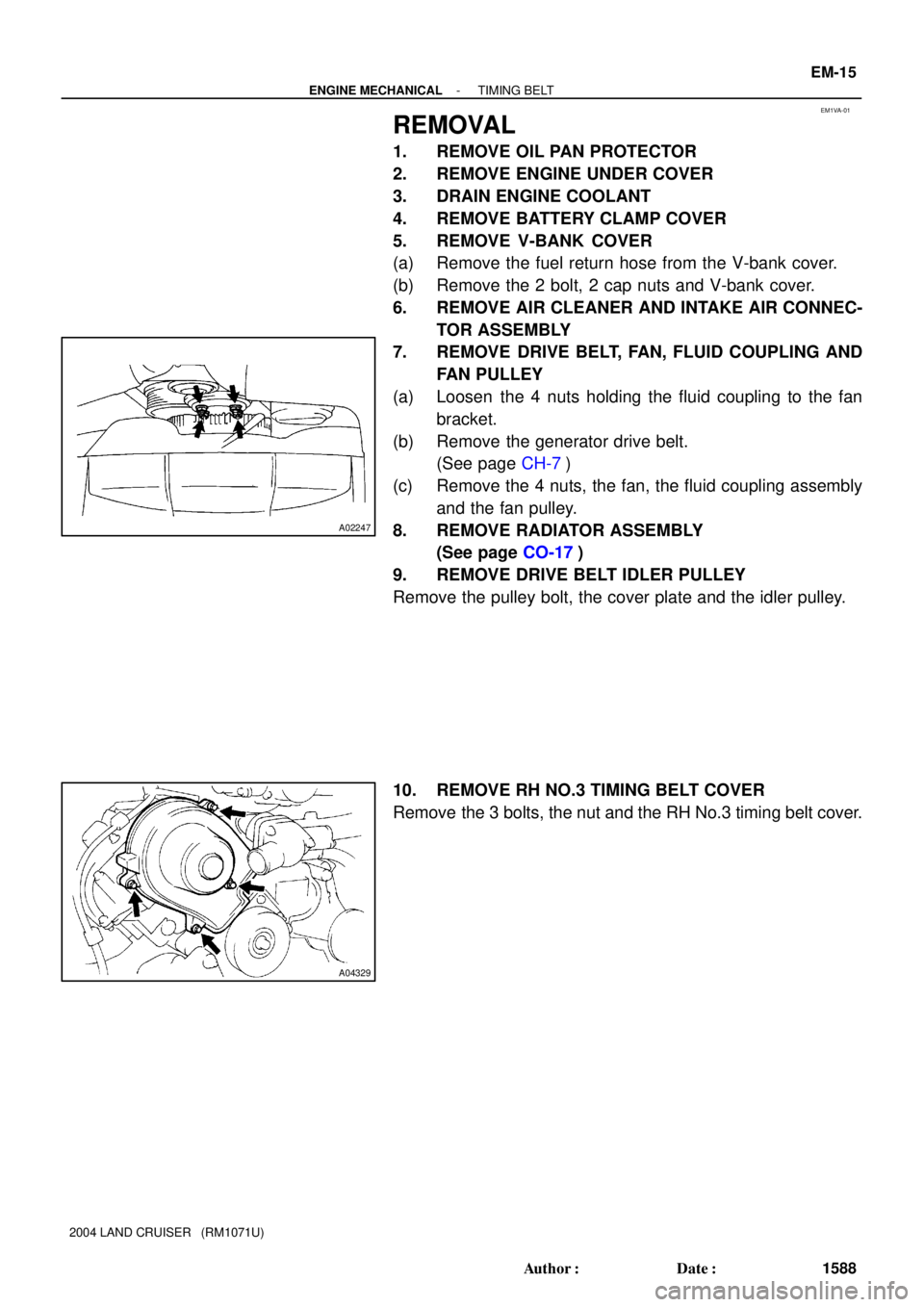
REMOVAL
1. REMOVE OIL PAN PROTECTOR
2. REMOVE ENGINE UNDER COVER
3. DRAIN ENGINE COOLANT
4. REMOVE BATTERY CLAMP COVER
5. REMOVE V-BANK COVER
(a) Remove the fuel return hose from the V-bank cover.
(b) Remove the 2 bolt, 2 cap nuts and V-bank cover.
6. REMOVE AIR CLEANER AND INTAKE AIR CONNEC-
TOR ASSEMBLY
7. REMOVE DRIVE BELT, FAN, FLUID COUPLING AND
FAN PULLEY
(a) Loosen the 4 nuts holding the fluid coupling to the fan
bracket.
(b) Remove the generator drive belt.
(See page CH-7)
(c) Remove the 4 nuts, the fan, the fluid coupling assembly
and the fan pulley.
8. REMOVE RADIATOR ASSEMBLY
(See page CO-17)
9. REMOVE DRIVE BELT IDLER PULLEY
Remove the pulley bolt, the cover plate and the idler pulley.
10. REMOVE RH NO.3 TIMING BELT COVER
Remove the 3 bolts, the nut and the RH No.3 timing belt cover.
Page 1898 of 3115

11. REMOVE LH NO.3 TIMING BELT COVER
(a) Disconnect the engine wire from the 2 wire")
A04331
A04330
A04455
A04332
EM-16
- ENGINE MECHANICALTIMING BELT
1589 Author�: Date�:
2004 LAND CRUISER (RM1071U)
11. REMOVE LH NO.3 TIMING BELT COVER
(a) Disconnect the engine wire from the 2 wire clamps.
(b) Remove the 4 bolts and the nut.
(c) Disconnect the camshaft position sensor wire from the
wire clamp on the LH No.3 timing belt cover.
(d) Disconnect the sensor connector from the connector
bracket.
(e) Disconnect the camshaft position sensor connector.
(f) Remove the wire grommet from the LH No.3 timing belt
cover.
(g) Remove the LH No.3 timing belt cover.
(h) Remove the oil cooler pipe and the 2 bolts.
12. REMOVE NO.2 TIMING BELT COVER
Remove the 2 bolts and the No.2 timing belt cover.
13. DISCONNECT A/C COMPRESSOR FROM ENGINE
(See page EM-77)
14. REMOVE FAN BRACKET
Remove the 2 bolts, the 2 nuts and the fan bracket.
15. IF RE-USING TIMING BELT, CHECK
INSTALLATION MARKS ON TIMING BELT
Check that there are 3 installation marks on the timing belt as
turning the crankshaft pulley as shown in the illustration.
HINT:
If the installation marks are disappeared, place a new installa-
tion mark on the timing belt before removing each part.
Page 1899 of 3115

16. LOOSEN CRANKSHAFT PULLEY BOLT
Using SST, loosen the pulle")
A09156
SST
A08597
Turn
A04335
A04337
A04338
String
- ENGINE MECHANICALTIMING BELT
EM-17
1590 Author�: Date�:
2004 LAND CRUISER (RM1071U)
16. LOOSEN CRANKSHAFT PULLEY BOLT
Using SST, loosen the pulley bolt.
SST 09213-7001 1 (90105-70020),
09330-00021
17. SET NO.1 CYLINDER TO TDC/COMPRESSION
(a) Turn the crankshaft pulley and align its groove with the
timing mark º0º of the No.1 timing belt cover.
(b) Check that the timing marks of the camshaft timing pul-
leys and that of the timing belt rear plates aligned.
If not, turn the crankshaft 1 revolution (360°).
(c) Remove the crankshaft pulley bolt.
NOTICE:
Do not turn the crankshaft pulley.
18. REMOVE TIMING BELT TENSIONER
HINT:
�When re-using timing belt:
If the installation marks are disappeared, place 2 new
installation marks on the timing belt to match the timing
marks of the camshaft timing pulleys before the removal.
�When replacing timing belt tensioner only:
To avoid meshing of the timing pulley and the timing belt,
secure one of them with string, and then place match-
marks on the timing belt and the RH camshaft timing
pulley.