Page 2455 of 3115
LU08P-07
B04470
B04791
RH No.3 Timing Belt Cover
LH No.3 Timing Belt CoverNo.2 Timing Belt Cover
Camshaft Position
Sensor Connector
Engine Wire
Drive Belt Idler PulleyTiming Belt
Fan Bracket
N´m (kgf´cm, ft´lbf) : Specified torqueOil Cooler Pipe
Timing Belt Tensioner Dust Boot
Cover Plate
39 (400,29)
245 (2,500, 181)
32 (330, 24)
16 (160, 12)
7.5 (80, 66 in.´lbf)
16 (160, 12)
Water Bypass
Hose
LU-4
- LUBRICATIONOIL PUMP
1785 Author�: Date�:
2004 LAND CRUISER (RM1071U)
OIL PUMP
COMPONENTS
Page 2456 of 3115
B04472
GeneratorDrive Belt Tensioner
No.1 Timing Belt Cover
Crankshaft Pulley
Timing Belt
Timing Belt Guide
(Crankshaft Angle Sensor Plate)No.1 Idler Pulley
Crankshaft Timing PulleyPlate Washer
No.2 Idler Pulley
Timing Belt Cover SpacerGasket
� Precoated part
N´m (kgf´cm, ft´lbf) : Specified torque
39 (400, 29)
34.5 (350, 25)�
34.5 (350, 25)
- LUBRICATIONOIL PUMP
LU-5
1786 Author�: Date�:
2004 LAND CRUISER (RM1071U)
Page 2464 of 3115

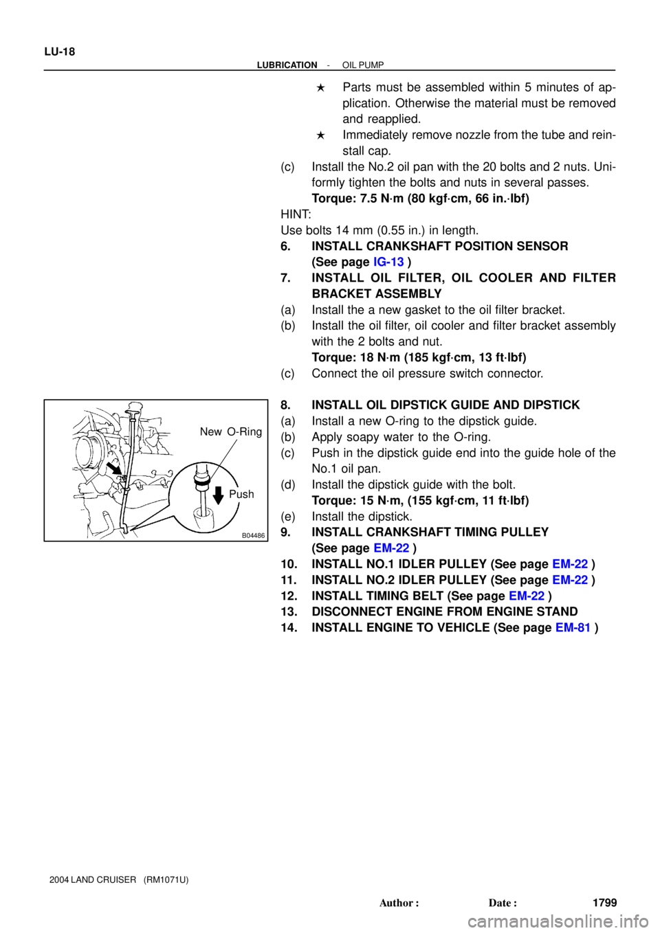
B04486
Push New O-Ring
LU-18
- LUBRICATIONOIL PUMP
1799 Author�: Date�:
2004 LAND CRUISER (RM1071U)
�Parts must be assembled within 5 minutes of ap-
plication. Otherwise the material must be removed
and reapplied.
�Immediately remove nozzle from the tube and rein-
stall cap.
(c) Install the No.2 oil pan with the 20 bolts and 2 nuts. Uni-
formly tighten the bolts and nuts in several passes.
Torque: 7.5 N´m (80 kgf´cm, 66 in.´lbf)
HINT:
Use bolts 14 mm (0.55 in.) in length.
6. INSTALL CRANKSHAFT POSITION SENSOR
(See page IG-13)
7. INSTALL OIL FILTER, OIL COOLER AND FILTER
BRACKET ASSEMBLY
(a) Install the a new gasket to the oil filter bracket.
(b) Install the oil filter, oil cooler and filter bracket assembly
with the 2 bolts and nut.
Torque: 18 N´m (185 kgf´cm, 13 ft´lbf)
(c) Connect the oil pressure switch connector.
8. INSTALL OIL DIPSTICK GUIDE AND DIPSTICK
(a) Install a new O-ring to the dipstick guide.
(b) Apply soapy water to the O-ring.
(c) Push in the dipstick guide end into the guide hole of the
No.1 oil pan.
(d) Install the dipstick guide with the bolt.
Torque: 15 N´m, (155 kgf´cm, 11 ft´lbf)
(e) Install the dipstick.
9. INSTALL CRANKSHAFT TIMING PULLEY
(See page EM-22)
10. INSTALL NO.1 IDLER PULLEY (See page EM-22)
11. INSTALL NO.2 IDLER PULLEY (See page EM-22)
12. INSTALL TIMING BELT (See page EM-22)
13. DISCONNECT ENGINE FROM ENGINE STAND
14. INSTALL ENGINE TO VEHICLE (See page EM-81)
Page 2466 of 3115

LU08Q-08
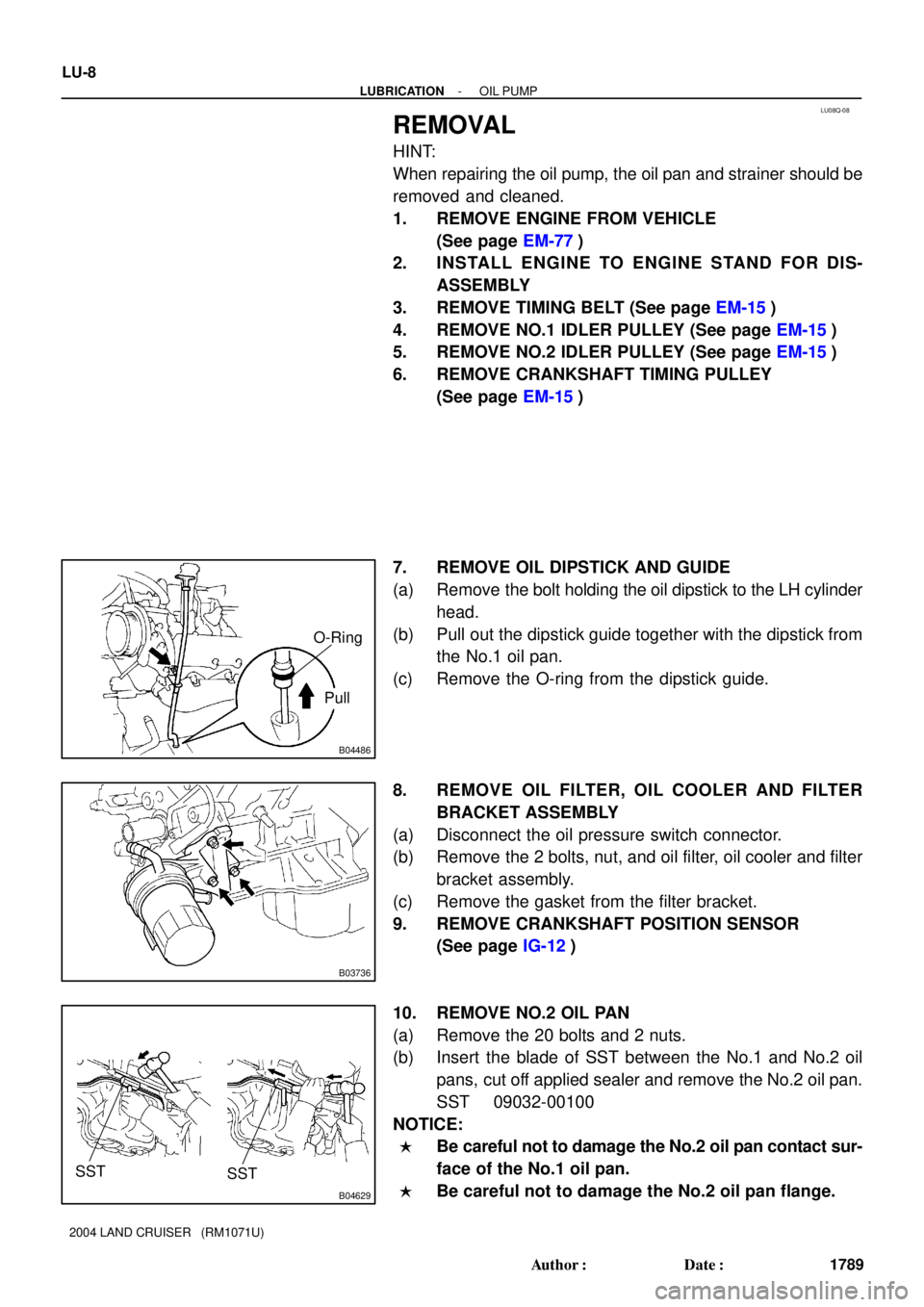
B04486
Pull O-Ring
B03736
B04629
SST SST
LU-8
- LUBRICATIONOIL PUMP
1789 Author�: Date�:
2004 LAND CRUISER (RM1071U)
REMOVAL
HINT:
When repairing the oil pump, the oil pan and strainer should be
removed and cleaned.
1. REMOVE ENGINE FROM VEHICLE
(See page EM-77)
2. INSTALL ENGINE TO ENGINE STAND FOR DIS-
ASSEMBLY
3. REMOVE TIMING BELT (See page EM-15)
4. REMOVE NO.1 IDLER PULLEY (See page EM-15)
5. REMOVE NO.2 IDLER PULLEY (See page EM-15)
6. REMOVE CRANKSHAFT TIMING PULLEY
(See page EM-15)
7. REMOVE OIL DIPSTICK AND GUIDE
(a) Remove the bolt holding the oil dipstick to the LH cylinder
head.
(b) Pull out the dipstick guide together with the dipstick from
the No.1 oil pan.
(c) Remove the O-ring from the dipstick guide.
8. REMOVE OIL FILTER, OIL COOLER AND FILTER
BRACKET ASSEMBLY
(a) Disconnect the oil pressure switch connector.
(b) Remove the 2 bolts, nut, and oil filter, oil cooler and filter
bracket assembly.
(c) Remove the gasket from the filter bracket.
9. REMOVE CRANKSHAFT POSITION SENSOR
(See page IG-12)
10. REMOVE NO.2 OIL PAN
(a) Remove the 20 bolts and 2 nuts.
(b) Insert the blade of SST between the No.1 and No.2 oil
pans, cut off applied sealer and remove the No.2 oil pan.
SST 09032-00100
NOTICE:
�Be careful not to damage the No.2 oil pan contact sur-
face of the No.1 oil pan.
�Be careful not to damage the No.2 oil pan flange.
Page 2475 of 3115
MA02S-01
MA-6
- MAINTENANCEENGINE
54 Author�: Date�:
2004 LAND CRUISER (RM1071U)
ENGINE
INSPECTION
HINT:
Inspect these items when the engine is cold.
1. REPLACE TIMING BELT (See page EM-15)
2. INSPECT VALVE CLEARANCE (See page EM-4)
3. INSPECT DRIVE BELT (See page CH-2)
4. REPLACE ENGINE OIL AND OIL FILTER (See page LU-2)
5. REPLACE ENGINE COOLANT (See page CO-2)
6. INSPECT EXHAUST PIPES AND MOUNTINGS
Visually inspect the pipes, hangers and connections for severe corrosion, leaks or damage.
7. REPLACE AIR CLEANER FILTER
Replace the air cleaner filter with a new one.
8. INSPECT FUEL LINES, CONNECTIONS AND FUEL VAPOR CONTROL VALVE (See page
EC-5)
Visually inspect the fuel lines for cracks, leakage loose connections, deformation or tank band looseness.
9. INSPECT GASKET IN FUEL TANK CAP (See page EC-5)
10. REPLACE SPARK PLUGS (See page IG-1)
11. California, Massachusetts and New York:
INSPECT CHARCOAL CANISTER (See page EC-5)
Page 2590 of 3115

SS0OQ-10
SS-4
- SERVICE SPECIFICATIONSENGINE MECHANICAL
144 Author�: Date�:
2004 LAND CRUISER (RM1071U)
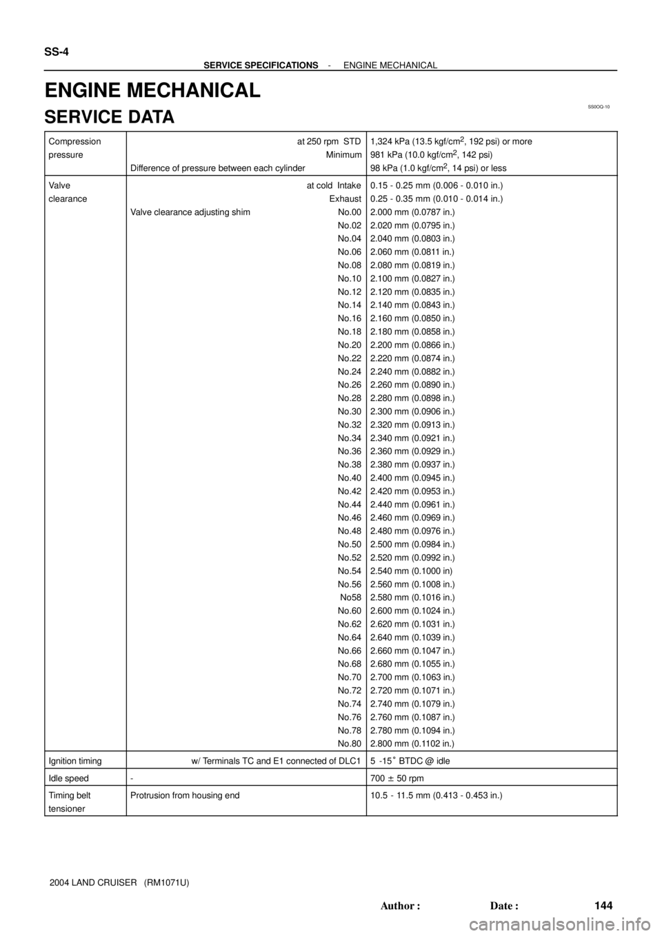
ENGINE MECHANICAL
SERVICE DATA
Compression
pressureat 250 rpm STD
Minimum
Difference of pressure between each cylinder1,324 kPa (13.5 kgf/cm2, 192 psi) or more
981 kPa (10.0 kgf/cm2, 142 psi)
98 kPa (1.0 kgf/cm2, 14 psi) or less
Valve
clearanceat cold Intake
Exhaust
Valve clearance adjusting shim No.00
No.02
No.04
No.06
No.08
No.10
No.12
No.14
No.16
No.18
No.20
No.22
No.24
No.26
No.28
No.30
No.32
No.34
No.36
No.38
No.40
No.42
No.44
No.46
No.48
No.50
No.52
No.54
No.56
No58
No.60
No.62
No.64
No.66
No.68
No.70
No.72
No.74
No.76
No.78
No.800.15 - 0.25 mm (0.006 - 0.010 in.)
0.25 - 0.35 mm (0.010 - 0.014 in.)
2.000 mm (0.0787 in.)
2.020 mm (0.0795 in.)
2.040 mm (0.0803 in.)
2.060 mm (0.0811 in.)
2.080 mm (0.0819 in.)
2.100 mm (0.0827 in.)
2.120 mm (0.0835 in.)
2.140 mm (0.0843 in.)
2.160 mm (0.0850 in.)
2.180 mm (0.0858 in.)
2.200 mm (0.0866 in.)
2.220 mm (0.0874 in.)
2.240 mm (0.0882 in.)
2.260 mm (0.0890 in.)
2.280 mm (0.0898 in.)
2.300 mm (0.0906 in.)
2.320 mm (0.0913 in.)
2.340 mm (0.0921 in.)
2.360 mm (0.0929 in.)
2.380 mm (0.0937 in.)
2.400 mm (0.0945 in.)
2.420 mm (0.0953 in.)
2.440 mm (0.0961 in.)
2.460 mm (0.0969 in.)
2.480 mm (0.0976 in.)
2.500 mm (0.0984 in.)
2.520 mm (0.0992 in.)
2.540 mm (0.1000 in)
2.560 mm (0.1008 in.)
2.580 mm (0.1016 in.)
2.600 mm (0.1024 in.)
2.620 mm (0.1031 in.)
2.640 mm (0.1039 in.)
2.660 mm (0.1047 in.)
2.680 mm (0.1055 in.)
2.700 mm (0.1063 in.)
2.720 mm (0.1071 in.)
2.740 mm (0.1079 in.)
2.760 mm (0.1087 in.)
2.780 mm (0.1094 in.)
2.800 mm (0.1102 in.)
Ignition timingw/ Terminals TC and E1 connected of DLC15 -15° BTDC @ idle
Idle speed-700 ± 50 rpm
Timing belt
tensionerProtrusion from housing end10.5 - 11.5 mm (0.413 - 0.453 in.)
Page 2594 of 3115

SS0OR-1 1
SS-8
- SERVICE SPECIFICATIONSENGINE MECHANICAL
148 Author�: Date�:
2004 LAND CRUISER (RM1071U)
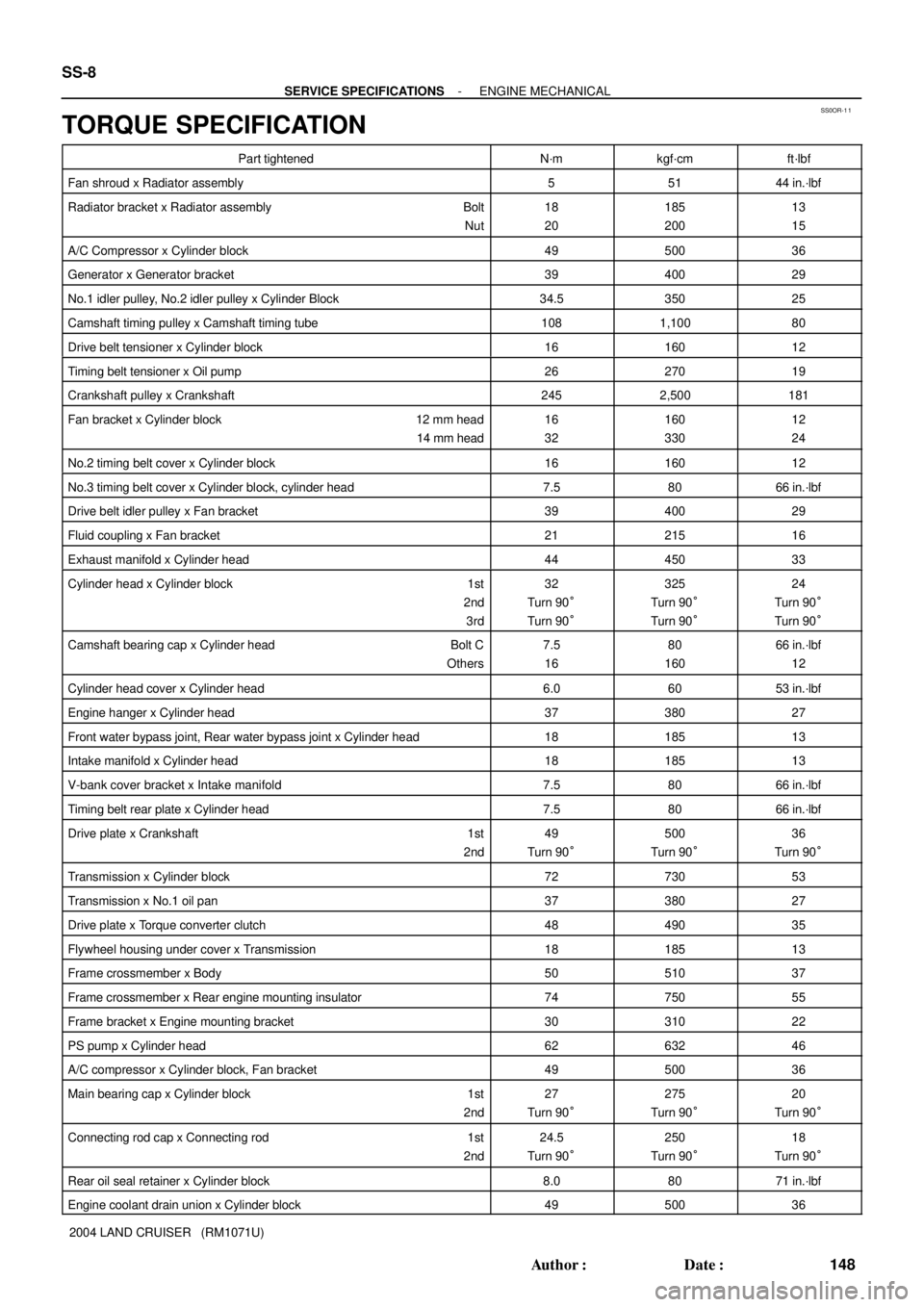
TORQUE SPECIFICATION
Part tightenedN´mkgf´cmft´lbf
Fan shroud x Radiator assembly55144 in.´lbf
Radiator bracket x Radiator assembly Bolt
Nut18
20185
20013
15
A/C Compressor x Cylinder block4950036
Generator x Generator bracket3940029
No.1 idler pulley, No.2 idler pulley x Cylinder Block34.535025
Camshaft timing pulley x Camshaft timing tube1081,10080
Drive belt tensioner x Cylinder block1616012
Timing belt tensioner x Oil pump2627019
Crankshaft pulley x Crankshaft2452,500181
Fan bracket x Cylinder block 12 mm head
14 mm head16
32160
33012
24
No.2 timing belt cover x Cylinder block1616012
No.3 timing belt cover x Cylinder block, cylinder head7.58066 in.´lbf
Drive belt idler pulley x Fan bracket3940029
Fluid coupling x Fan bracket2121516
Exhaust manifold x Cylinder head4445033
Cylinder head x Cylinder block 1st
2nd
3rd32
Turn 90°
Turn 90°325
Turn 90°
Turn 90°24
Turn 90°
Turn 90°
Camshaft bearing cap x Cylinder head Bolt C
Others7.5
1680
16066 in.´lbf
12
Cylinder head cover x Cylinder head6.06053 in.´lbf
Engine hanger x Cylinder head3738027
Front water bypass joint, Rear water bypass joint x Cylinder head1818513
Intake manifold x Cylinder head1818513
V-bank cover bracket x Intake manifold7.58066 in.´lbf
Timing belt rear plate x Cylinder head7.58066 in.´lbf
Drive plate x Crankshaft 1st
2nd49
Turn 90°500
Turn 90°36
Turn 90°
Transmission x Cylinder block7273053
Transmission x No.1 oil pan3738027
Drive plate x Torque converter clutch4849035
Flywheel housing under cover x Transmission1818513
Frame crossmember x Body5051037
Frame crossmember x Rear engine mounting insulator7475055
Frame bracket x Engine mounting bracket3031022
PS pump x Cylinder head6263246
A/C compressor x Cylinder block, Fan bracket4950036
Main bearing cap x Cylinder block 1st
2nd27
Turn 90°275
Turn 90°20
Turn 90°
Connecting rod cap x Connecting rod 1st
2nd24.5
Turn 90°250
Turn 90°18
Turn 90°
Rear oil seal retainer x Cylinder block8.08071 in.´lbf
Engine coolant drain union x Cylinder block4950036