Page 6 of 3115
AC3P1-01
I25173
C10 C19
: Bulb
I07872
I25174
C22 C12
AC-104
- AIR CONDITIONINGAIR CONDITIONING CONTROL ASSEMBLY
2829 Author�: Date�:
2004 LAND CRUISER (RM1071U)
INSPECTION
1. w/o Navigation system:
INSPECT ILLUMINATION OPERATION
(a) Connect the positive (+) lead from the battery to terminal
C10 and negative (-) lead to terminal C19, then check
that the indicators illuminate.
If operation is not as specified, check the faulty bulb.
(b) Remove the bulb.
(c) Using the tester as shown in the illustration, test the conti-
nuity.
If continuity exists, replace the heater control.
If no continuity exists, replace the bulb.
2. w/o Navigation system:
INSPECT INDICATORS OPERATION
(a) Connect the positive (+) lead from the battery to terminal
C22 and negative (-) lead to terminal C12.
(b) Check that the indicators come on while operate the
switches.
If operation is not as specified, replace the heater control.
3. INSPECT A/C CONTROL ASSEMBLY CIRCUIT
(See page DI-1309)
Page 82 of 3115

2807 Author�: Date�:
2004 LAND CRUISER (RM1071U)
POWER TRANSISTOR (for Rear
Cooler)
INSPECTION
1. RE")
AC1LI-04
I06760
I07763
21
4
I07764
3
4 AC-82
- AIR CONDITIONINGPOWER TRANSISTOR (for Rear Cooler)
2807 Author�: Date�:
2004 LAND CRUISER (RM1071U)
POWER TRANSISTOR (for Rear
Cooler)
INSPECTION
1. REMOVE REAR DOOR SCUFF PLATE RH
2. REMOVE REAR FLOOR MAT SUPPORT PLATE
3. REMOVE QUARTER TRIM PANEL RH
4. REMOVE POWER TRANSISTOR
(a) Disconnect the connector.
(b) Remove the 2 screws and the power transistor.
5. INSPECT POWER TRANSISTOR OPERATION
(a) Connect the positive (+) lead to terminal 1 through a
12 V - 3.4 W test bulb and negative (-) lead to
terminal 2.
(b) Check the test bulb comes on when another positive (+)
lead is connected to terminal 4 through a 12 V - 3.4 W test
bulb.
If operation is not as specified, replace the power transistor.
6. INSPECT POWER TRANSISTOR RESISTANCE
Measure resistance between terminals 3 and 4.
Standard resistance: 2.0 - 2.4 kW
If resistance is not as specified, replace the power transistor.
7. INSTALL POWER TRANSISTOR
(a) Install the power transistor with 2 screws.
(b) Connect the connector.
8. INSTALL QUARTER TRIM PANEL RH
9. INSTALL REAR FLOOR MAT SUPPORT PLATE
10. INSTALL REAR DOOR SCUFF PLATE RH
Page 131 of 3115
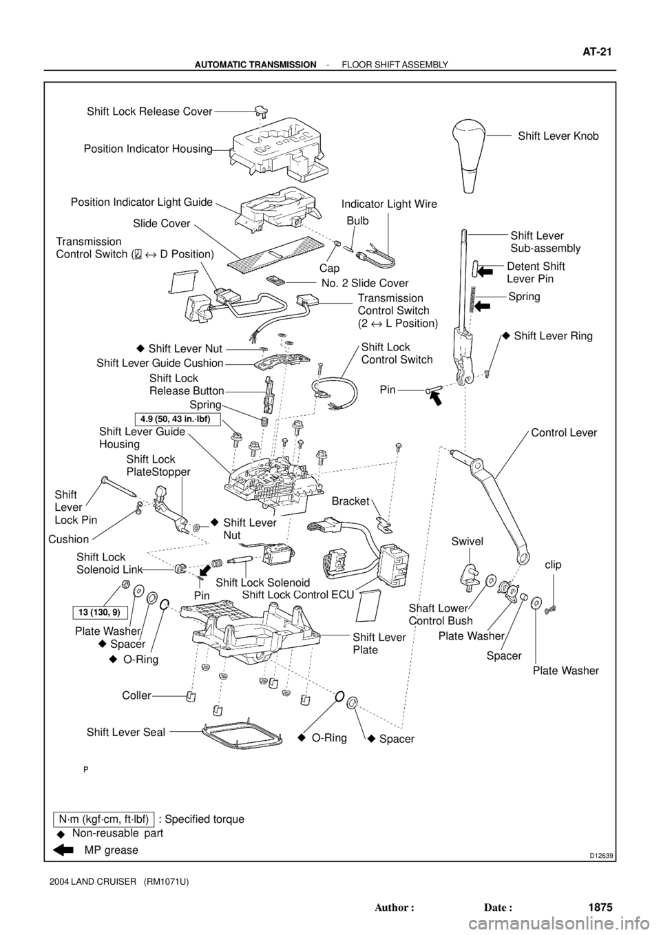
D12639
Position Indicator Housing
Position Indicator Light Guide
Slide Cover
No. 2 Slide Cover
� Shift Lever Nut
Shift Lever Guide Cushion
Shift Lever Guide
Housing
Bracket
Shift Lock Control ECU
Coller
13 (130, 9)
Plate Washer
� Spacer � O-Ring Shift Lever Seal� O-Ring � SpacerSwivel
Plate Washer
Spacer Shaft Lower
Control Bushclip
Plate Washer Control Lever
�
Pin
� Shift Lever Ring Spring Detent Shift
Lever PinShift Lever
Sub-assembly
Shift Lock Solenoid
Shift Lever
NutPinShift Lever Knob
Transmission
Control Switch (
e D Position)
Shift Lock
Control Switch CapBulb Indicator Light Wire
Shift Lock
Release Button
Spring
N´m (kgf´cm, ft´lbf) : Specified torque
�
MP grease Non-reusable partShift Lever
PlateTransmission
Control Switch
(2 e L Position)
Shift Lock
Solenoid Link
Shift
Lever
Lock Pin
4.9 (50, 43 in.´lbf)
Shift Lock Release Cover
Cushion
Shift Lock
PlateStopper
- AUTOMATIC TRANSMISSIONFLOOR SHIFT ASSEMBLY
AT-21
1875 Author�: Date�:
2004 LAND CRUISER (RM1071U)
Page 206 of 3115

BODY ELECTRICAL SYSTEM
PRECAUTION
HINT:
Take care to observe the following precautions when per")
BE01I-05
- BODY ELECTRICALBODY ELECTRICAL SYSTEM
BE-1
2374 Author�: Date�:
2004 LAND CRUISER (RM1071U)
BODY ELECTRICAL SYSTEM
PRECAUTION
HINT:
Take care to observe the following precautions when performing inspections or removal and replacement
of body electrical related parts.
1. HEADLIGHT SYSTEM
Halogen bulbs have pressurized gas inside and require special handling. They can burst if scratched or
dropped. Hold a bulb only by its plastic or metal case. Don't touch the glass part of a bulb with bare hands.
2. SRS (SUPPLEMENTAL RESTRAINT SYSTEM)
The LAND CRUISER is equipped with an SRS (Supplemental Restraint System) such as the driver airbag
and front passenger airbag. Failure to carry out service operation in the correct sequence could cause the
SRS to unexpectedly deploy during servicing, possibly leading to a serious accident. Before servicing (in-
cluding removal or installation of parts, inspection or replacement), be sure to read the precautionary notices
in the RS section.
3. AUDIO SYSTEM
�If the negative (-) terminal cable is disconnected from the battery, the preset AM, FM 1 and FM 2 sta-
tions stored in memory are erased, so be sure to note the stations and reset them after the negative
(-) terminal cable is reconnected to the battery.
�If the negative (-) terminal cable is disconnected from the battery, the ºANTI-THEFT SYSTEMº will
operate when the cable is reconnected, but the radio, tape player and CD player will not operate. Be
sure to input the correct ID number so that the radio, tape player and CD player can be operated again.
4. MOBILE COMMUNICATION SYSTEM
If the vehicle is equipped with a mobile communication system, refer to precautions in the IN section.
Page 258 of 3115

INSPECTION
1. INSPECT FRONT PERSONAL LIGHT")
BE2EG-01
I25786
1
2 3
I25795
1
2 3
I25795
N01731
2
N01732
2
1 BE-44
- BODY ELECTRICALINTERIOR LIGHT SYSTEM
2417 Author�: Date�:
2004 LAND CRUISER (RM1071U)
INSPECTION
1. INSPECT FRONT PERSONAL LIGHT SWITCH CONTI-
NUITY
Switch positionTester connectionSpecified condition
OFF-No continuity
ON1 - 2Continuity
If continuity is not as specified, replace the light assembly or
bulb.
2. INSPECT REAR PERSONAL LIGHT SWITCH CONTI-
NUITY
Switch positionTester connectionSpecified condition
OFF-No continuity
ON1 - 3Continuity
If continuity is not as specified, replace the light assembly or
bulb.
3. INSPECT ROOM LIGHT SWITCH CONTINUITY
Switch positionTester connectionSpecified condition
Room Light Switch OFF-No continuity
Room Light Switch DOOR2 - 3Continuity
Room Light Switch ON1 - 3Continuity
If continuity is not as specified, replace the light assembly or
bulb.
4. INSPECT REAR ROOM LIGHT SWITCH CONTINUITY
(a) Disconnect the connector from room light assembly.
(b) Turn the room light switch ON, check that continuity exists
between terminal 2 and body ground.
(c) Turn the room light switch DOOR, check that continuity
exists between terminal 1 and 2.
If operation is not as specified, replace the light assembly or
bulb.
Page 259 of 3115

I04050
21
OFFON
I06423
ON
OFF
I06431e-2-2-J
I06432
Back Door Lock Assembly
� Back Door Courtesy Switch
I06433ON
OFF1 2
- BODY ELECTRICALINTERIOR LIGHT SYSTEM
BE-45
2418 Author�: Date�:
2004 LAND CRUISER (RM1071U)
5. INSPECT VANITY LIGHT CONTINUITY
Switch positionTester connectionSpecified condition
OFF (closed)-No continuity
ON (opened)1 - 2Continuity
If continuity is not as specified, replace the vanity light assembly
or bulb.
6. INSPECT DOOR COURTESY SWITCH CONTINUITY
(a) Check that continuity exists between terminal and switch
body with the switch ON (switch pin released).
(b) Check that no continuity exists between terminal and
switch body with the switch OFF (switch pin pushed).
If continuity is not as specified, replace the switch.
7. INSPECT DOOR COURTESY LIGHT CONTINUITY
Using an ohmmeter, check that continuity exists between termi-
nals.
If continuity is not as specified, replace the light assembly or
bulb.
8. INSPECT BACK DOOR COURTESY SWITCH CONTI-
NUITY
Switch positionTester connectionSpecified condition
OFF (closed)-No continuity
ON (opened)1 - 2Continuity
If continuity is not as specified, replace the back door lock as-
sembly.
9. INSPECT GLOVE COMPARTMENT DOOR COURTE-
SY SWITCH CONTINUITY
Switch positionTester connectionSpecified condition
OFF (closed)-No continuity
ON (opened)1 - 2Continuity
If continuity is not as specified, replace the switch.
Page 260 of 3115
I06434e-2-2-J
BE-46
- BODY ELECTRICALINTERIOR LIGHT SYSTEM
2419 Author�: Date�:
2004 LAND CRUISER (RM1071U)
10. INSPECT LICENCE PLATE LIGHT CONTINUITY
Using an ohmmeter, check that continuity exists between termi-
nals.
If continuity is not as specified, replace the light assembly or
bulb.
Page 263 of 3115

INSPECTION
1. INSPECT FRONT PERSONAL LIGHT")
BE2EG-01
I25786
1
2 3
I25795
1
2 3
I25795
N01731
2
N01732
2
1 BE-44
- BODY ELECTRICALINTERIOR LIGHT SYSTEM
2417 Author�: Date�:
2004 LAND CRUISER (RM1071U)
INSPECTION
1. INSPECT FRONT PERSONAL LIGHT SWITCH CONTI-
NUITY
Switch positionTester connectionSpecified condition
OFF-No continuity
ON1 - 2Continuity
If continuity is not as specified, replace the light assembly or
bulb.
2. INSPECT REAR PERSONAL LIGHT SWITCH CONTI-
NUITY
Switch positionTester connectionSpecified condition
OFF-No continuity
ON1 - 3Continuity
If continuity is not as specified, replace the light assembly or
bulb.
3. INSPECT ROOM LIGHT SWITCH CONTINUITY
Switch positionTester connectionSpecified condition
Room Light Switch OFF-No continuity
Room Light Switch DOOR2 - 3Continuity
Room Light Switch ON1 - 3Continuity
If continuity is not as specified, replace the light assembly or
bulb.
4. INSPECT REAR ROOM LIGHT SWITCH CONTINUITY
(a) Disconnect the connector from room light assembly.
(b) Turn the room light switch ON, check that continuity exists
between terminal 2 and body ground.
(c) Turn the room light switch DOOR, check that continuity
exists between terminal 1 and 2.
If operation is not as specified, replace the light assembly or
bulb.