Page 241 of 3115
BE0RU-04
I25046
A-bolt
BE-38
- BODY ELECTRICALFOG LIGHT SYSTEM
2411 Author�: Date�:
2004 LAND CRUISER (RM1071U)
ADJUSTMENT
ADJUST FOGLIGHT AIM
A-bolt : Vertical Direction
Page 242 of 3115
BE0RT-04
I06374
ON
OFF
I25040
Built in relayExcept built in relay
- BODY ELECTRICALFOG LIGHT SYSTEM
BE-37
2410 Author�: Date�:
2004 LAND CRUISER (RM1071U)
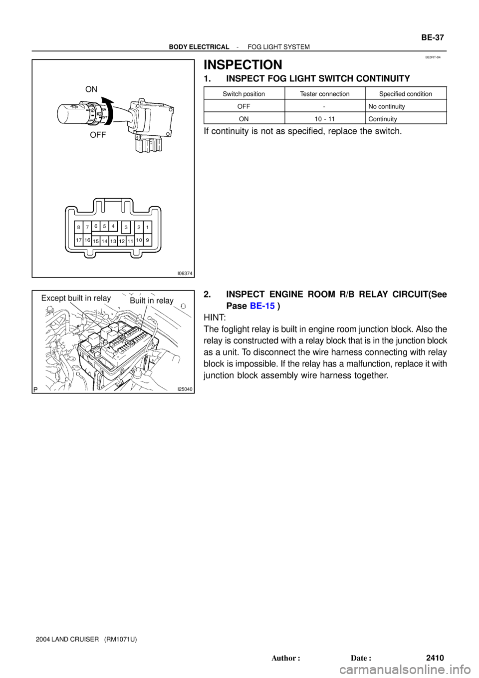
INSPECTION
1. INSPECT FOG LIGHT SWITCH CONTINUITY
Switch positionTester connectionSpecified condition
OFF-No continuity
ON10 - 11Continuity
If continuity is not as specified, replace the switch.
2. INSPECT ENGINE ROOM R/B RELAY CIRCUIT(See
Pase BE-15)
HINT:
The foglight relay is built in engine room junction block. Also the
relay is constructed with a relay block that is in the junction block
as a unit. To disconnect the wire harness connecting with relay
block is impossible. If the relay has a malfunction, replace it with
junction block assembly wire harness together.
Page 243 of 3115
BE0H2-16
I24736
Front Fog Light
Combination Switch
� Front Fog Light Switch
Engine Room R/B
� FR FOG Relay
� FR FOG Fuse
BE-36
- BODY ELECTRICALFOG LIGHT SYSTEM
2409 Author�: Date�:
2004 LAND CRUISER (RM1071U)
FOG LIGHT SYSTEM
LOCATION
Page 292 of 3115

- BODY ELECTRICALPOWER SOURCE
BE-19
2392 Author�: Date�:
2004 LAND CRUISER (RM1071U)
(a) Remove the fuse from the junction block and inspect the
connector on junction block side.
Fuse Tester connectionConditionSpecified condition
TOWING 1 - GroundConstantBattery positive voltage
MIR HTR 3 - GroundConstantBattery positive voltage
RR HTR 5 - GroundConstantBattery positive voltage
HAZ-TRN 7 - GroundConstantBattery positive voltage
ALT-S 9 - GroundConstantBattery positive voltage
NV-IR 13 - GroundConstantBattery positive voltage
FR FOG 13 - GroundConstantBattery positive voltage
BRK CTRL 15 - GroundConstantBattery positive voltage
HEAD CLNER 17 - GroundIgnition switch ONBattery positive voltage
FR-IG 19 - GroundIgnition switch ONBattery positive voltage
PANEL 21 - GroundLight control switch HEAD or TAILBattery positive voltage
TOWING TAIL 23 - GroundLight control switch HEAD or TAILBattery positive voltage
TAIL 25 - GroundLight control switch HEAD or TAILBattery positive voltage
BAT 29 - GroundConstantBattery positive voltage
TEL 31 - GroundConstantBattery positive voltage
AMP 33 - GroundConstantBattery positive voltage
EFI or ECD NO.1 35 - GroundConstantBattery positive voltage
AM2 37 - GroundConstantBattery positive voltage
ETCS 39 - GroundConstantBattery positive voltage
HORN 41 - GroundConstantBattery positive voltage
HEAD LH-UPR 51 - GroundLight control switch HI or FlashBattery positive voltage
HEAD RH-UPR 49 - GroundLight control switch HI or FlashBattery positive voltage
HEAD LH-LWR 47 - GroundLight control switch HEADBattery positive voltage
HEAD RH-LWR 45 - GroundLight control switch HEADBattery positive voltage
ST1 1 - GroundConstantBattery positive voltage
AHC 1 - GroundConstantBattery positive voltage
ABS NO.1 1 - GroundConstantBattery positive voltage
ABS NO.2 1 - GroundConstantBattery positive voltage
STARTER 1 - GroundConstantBattery positive voltage
If the circuit is not as specified, inspect the circuits connected
to other parts.
(b) Remove the relay from the junction block and inspect the
connector on junction block side.
Relay Tester connectionConditionSpecified condition
AHC 1 - GroundIgnition switch ONBattery positive voltage
ABS SOL 1 - GroundIgnition switch ONBattery positive voltage
ABS MTR1 1 - GroundConstantBattery positive voltage
ABS MTR2 1 - GroundIgnition switch ONBattery positive voltage
STARTER 5 - GroundConstantContinuity
STARTER 2 - GroundIgnition switch ONBattery positive voltage
EFI or ECD 3 - GroundConstantBattery positive voltage
C/OPN SPIL VLV 5 - GroundConstantBattery positive voltage
C/OPN SPIL VLV 2 - GroundIgnition switch ONContinuity
Page 336 of 3115
- BODY ELECTRICALTROUBLESHOOTING
BE-3
2376 Author�: Date�:
2004 LAND CRUISER (RM1071U) Headlight does not come on.
1. Engine Room J/B Relay Circuit
2. Body ECU
3. Daytime Running Light No.3, 4 Relays
4. Headlight Dimmer Switch
5. Light Control Switch
6. Wire Harness
7. BulbBE-15
BE-32
BE-32
BE-32
BE-32
-
-
Headlight does not come on with light control switch in HEAD.1. Light Control Switch
2. Wire HarnessBE-32
-
Headlight does not go out with light control switch in OFF.1. Engine Room J/B Relay Circuit
2. Wire HarnessBE-15
-
Headlight flickers.1. Bulb
2. Wire Harness-
-
Headlight is dark.1. Bulb
2. Wire Harness-
-
Taillight does not come on with light control switch in TAIL.
1. Engine Room J/B Relay Circuit
2. Light Control Switch
3. Wire HarnessBE-15
BE-32
-
Taillight does not go out with light control switch in OFF.
1. Engine Room J/B Relay Circuit
2. Light Control Switch
3. Wire HarnessBE-15
BE-32
-
Headlight does not come on with engine running and light control
switch in OFF.
1. ECU-B1 Fuse
2. ECU-IG1 Fuse
3. Body ECU
4. Daytime Running Light No.3, 4 Relays
5. Generator L Terminal
6. Parking Brake Switch
7. Wire Harness-
-
BE-32
BE-32
CH-10
BE-63
-
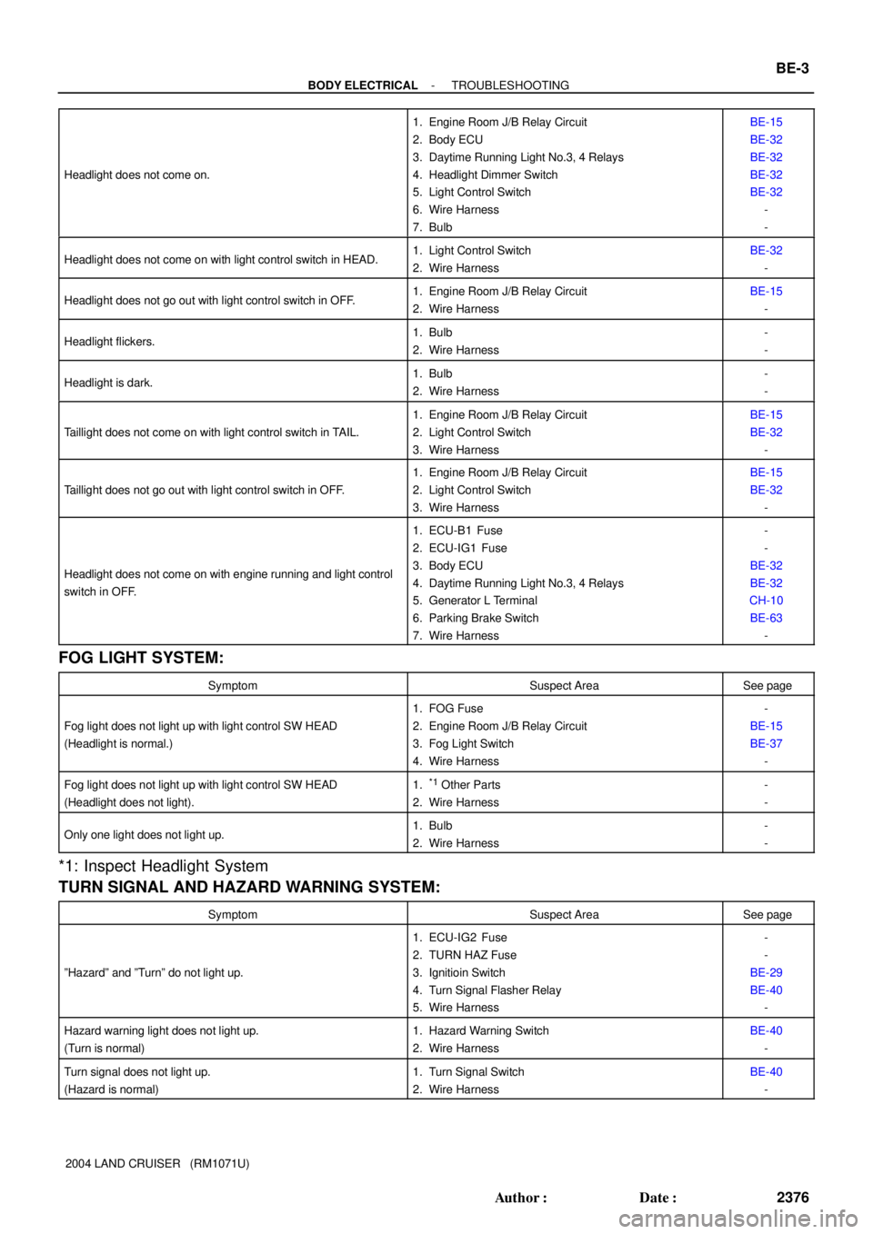
FOG LIGHT SYSTEM:
SymptomSuspect AreaSee page
Fog light does not light up with light control SW HEAD
(Headlight is normal.)
1. FOG Fuse
2. Engine Room J/B Relay Circuit
3. Fog Light Switch
4. Wire Harness-
BE-15
BE-37
-
Fog light does not light up with light control SW HEAD
(Headlight does not light).1.*1 Other Parts
2. Wire Harness-
-
Only one light does not light up.1. Bulb
2. Wire Harness-
-
*1: Inspect Headlight System
TURN SIGNAL AND HAZARD WARNING SYSTEM:
SymptomSuspect AreaSee page
ºHazardº and ºTurnº do not light up.
1. ECU-IG2 Fuse
2. TURN HAZ Fuse
3. Ignitioin Switch
4. Turn Signal Flasher Relay
5. Wire Harness-
-
BE-29
BE-40
-
Hazard warning light does not light up.
(Turn is normal)1. Hazard Warning Switch
2. Wire HarnessBE-40
-
Turn signal does not light up.
(Hazard is normal)1. Turn Signal Switch
2. Wire HarnessBE-40
-
Page 341 of 3115
BE-8
- BODY ELECTRICALTROUBLESHOOTING
2381 Author�: Date�:
2004 LAND CRUISER (RM1071U) ECT PWR indicator light does not light up.
1. LED
2. ECT Pattern Select Switch
3. Combination Meter
4. Wire Harness
5. ECT System-
-
BE-58
-
DI-358
2nd start ETCS indicator light does not light up.
1. LED
2. Combination Meter
3. Wire Harness
4. ECM-
BE-58
-
DI-1
Center Diff. lock indicator light does not light up.
1. LED
2. Combination Meter
3. Transfer 4WD Position Detection Switch
4. Wire Harness-
BE-58
TR-49
-
Indicator lights do not light up. (Except Turn, Hi-beam and
security)1. GAUGE2 Fuse
2. Wire Harness-
-
DEFOGGER SYSTEM:
SymptomSuspect AreaSee page
All defogger systems do not operate.
1. DEFOG Fuse
2. DEFOG Relay
3. Defogger Switch (Integration Control Panel Assembly)
4. Wire Harness-
-
BE-75
-
Rear window defogger does not operate.
1. Defogger Wire
2. Choke Coil
3. Wire HarnessBE-75
-
-
Mirror defogger does not operate.
1. MIR HTR Fuse
2. Engine Room J/B Relay Circuit
3. Mirror Defogger
4. Wire Harness-
BE-15
BE-75
-
POWER WINDOW CONTROL SYSTEM:
This system uses the multiplex communication system, so check diagnosis system of the multiplex commu-
nication system before you proceed with troubleshooting.
SymptomSuspect AreaSee page
All the power windows do not operate.
(Power Door Lock System is normal.)1. P/W (FL, FR, RL, RR) Fuse
2. Power Window Master Switch
3. Wire Harness-
BE-79
-
Only the driver's window does not operate.
1. Power Window Master Switch
2. Body ECU
3. Power Window Motor
4. Wire HarnessBE-79
DI-1038
BE-79
-
ºWindow lock functionº does not operate.1. Power Window Master SwitchBE-79
POWER DOOR LOCK CONTROL SYSTEM:
This system uses the body control system, so check diagnosis system of the body control system before
you proceed with troubleshooting.
SymptomSuspect AreaSee page
All the doors cannot be locked or unlocked.
(Power Window Control System is normal.)
1. DOOR Fuse
2. Door Lock Control Switch
3. Wire Harness
4. Body ECU-
BE-88
-
DI-1038
Only one side door lock control does not operate.1. Door Lock Motor
2. Wire HarnessBE-88
-
Page 379 of 3115
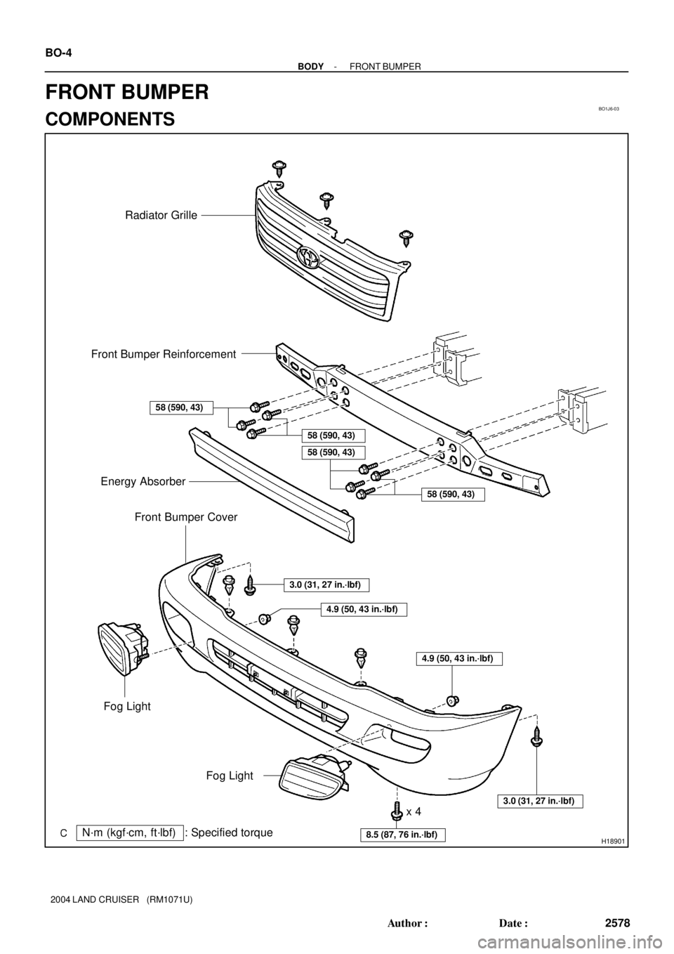
BO1J6-03
H18901
Energy Absorber
Fog LightRadiator Grille
: Specified torque
N´m (kgf´cm, ft´lbf)
3.0 (31, 27 in.´lbf)
Front Bumper Cover
x 4
58 (590, 43)
58 (590, 43)
58 (590, 43)
8.5 (87, 76 in.´lbf)
3.0 (31, 27 in.´lbf)
4.9 (50, 43 in.´lbf)
4.9 (50, 43 in.´lbf)
Front Bumper Reinforcement
58 (590, 43)
Fog Light BO-4
- BODYFRONT BUMPER
2578 Author�: Date�:
2004 LAND CRUISER (RM1071U)
FRONT BUMPER
COMPONENTS
Page 598 of 3115
CH0JZ-02
B04539
B04881
Except Maintenance-Free Battery
B04538
Voltmeter
Maintenance-Free Battery
Z11580
Charging
NecessaryInsufficient
Water Blue White Red
OK
Maintenance-Free Battery CH-2
- CHARGINGCHARGING SYSTEM
1837 Author�: Date�:
2004 LAND CRUISER (RM1071U)
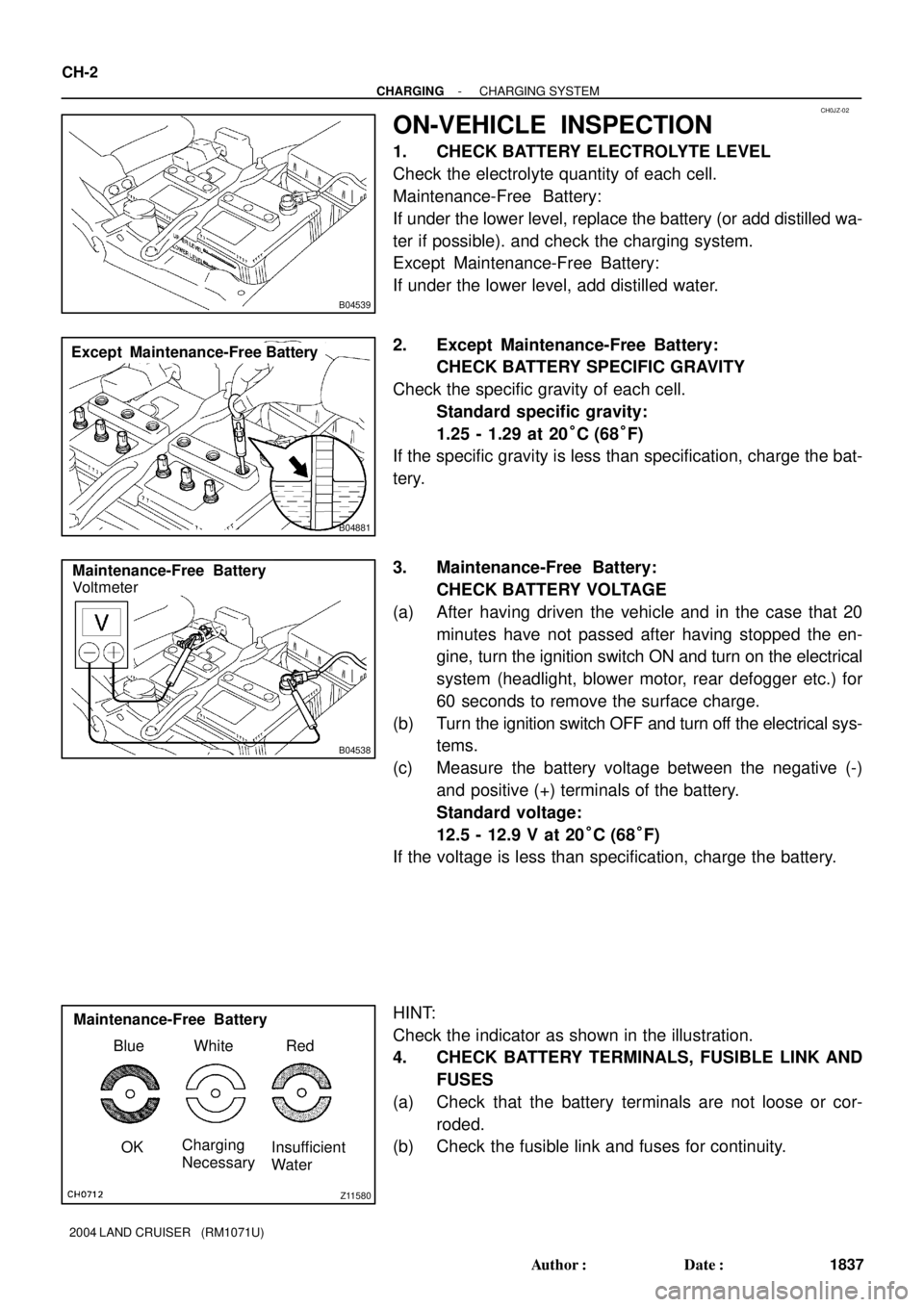
ON-VEHICLE INSPECTION
1. CHECK BATTERY ELECTROLYTE LEVEL
Check the electrolyte quantity of each cell.
Maintenance-Free Battery:
If under the lower level, replace the battery (or add distilled wa-
ter if possible). and check the charging system.
Except Maintenance-Free Battery:
If under the lower level, add distilled water.
2. Except Maintenance-Free Battery:
CHECK BATTERY SPECIFIC GRAVITY
Check the specific gravity of each cell.
Standard specific gravity:
1.25 - 1.29 at 20°C (68°F)
If the specific gravity is less than specification, charge the bat-
tery.
3. Maintenance-Free Battery:
CHECK BATTERY VOLTAGE
(a) After having driven the vehicle and in the case that 20
minutes have not passed after having stopped the en-
gine, turn the ignition switch ON and turn on the electrical
system (headlight, blower motor, rear defogger etc.) for
60 seconds to remove the surface charge.
(b) Turn the ignition switch OFF and turn off the electrical sys-
tems.
(c) Measure the battery voltage between the negative (-)
and positive (+) terminals of the battery.
Standard voltage:
12.5 - 12.9 V at 20°C (68°F)
If the voltage is less than specification, charge the battery.
HINT:
Check the indicator as shown in the illustration.
4. CHECK BATTERY TERMINALS, FUSIBLE LINK AND
FUSES
(a) Check that the battery terminals are not loose or cor-
roded.
(b) Check the fusible link and fuses for continuity.