Page 158 of 3115

N17398
Example:
HeadCapstan
Pinch Roller BE-126
- BODY ELECTRICALAUDIO SYSTEM
2499 Author�: Date�:
2004 LAND CRUISER (RM1071U)
(b) Matters that require attention when checking:
�Noise coming into the radio usually has no harm for
daily use as the noise protection is taken, and it is
very rate for an extremely loud noise to come in.
When extremely loud noise comes into the radio,
check if the grounding is normal where the antenna
is installed.
�Check if all the regular noise prevention parts are
properly installed, and if there is any installation of
non-authorized parts and non-authorized wiring.
�If you leave the radio under out of tune (not turning),
it is easy to diagnose the phenomenon as noise oc-
curs frequently.
(c) Antenna and noise:
Electronic signal received by the antenna will reach to the
radio transmitting through the core wire of the coaxial
cable. Any noise wave other than radio wave is mixed into
this core wire, that naturally causes noise in the radio and
poor sound quality. In order to prevent the noise from
coming into radio, the core wire inside the coaxial cable
is covered with a mesh wire called shield wire which trans-
mits the noise to the ground.
5. COMPACT DISC PLAYER
Compact Disc Players use a laser beam pick-up to read the dig-
ital signals recorded on the CD and reproduce analog signals
of the music, etc.
HINT:
Never attempt to disassemble or oil any part of the player unit.
Do not insert any object other than a disc into the magazine.
NOTICE:
CD players use an invisible laser beam which could cause
hazardous radiation exposure. Be sure to operate the play-
er correctly as instructed.
6. Tape player/head cleaning:
MAINTENANCE
(a) Raise the cassette door with your finger.
Next, using a pencil or similar object, push in the guide.
(b) Using a cleaning pen or cotton applicator soaked in clean-
er, clean the head surface, pinch rollers and capstans.
Page 212 of 3115
MET Fuse Light Control Switch Flasher Relay
ABS, TRC, VSC ECU ABS, TRC, VSC ECU Drive Monitor H/L R-HI Fuse Body ECU
ABS, TRC, VSC ECU
ABS & BA & TRAC & VSC Actuator ECM
ABS, TRC, VSC ECU
Airbag ECU
Oil Pressure Sender Gauge Airbag ECU Body ECUWiring connector side No.107 6
19 18 175 3
12
20 15
16
17
18
19
7 4 1
C14 C13 C12
11
Gateway ECU
ECM Engine Ground
Main Fuel Sender Gauge
7
19
201
2
4
C15Key Unlock Warning Switch 9CTR DIFF Switch 14
Drive Monitor 16 10 ECM
Body (Door Courtesy Switch Signal) 10Flasher Relay 4
ABS, TRC, VSC ECU
ABS, TRC, VSC ECU
ABS, TRC, VSC ECU
GAUGE1 Fuse
ECU-B2 Fuse
ACC Fuse
DOME Fuse
Speed Sensor 11
12
13
14
15Main Fuel Sender Gauge
Light Control Rheostat 6 Main Fuel Sender GaugeBody Ground 9
Speed Control Unit 16PANEL Fuse 8
11 Driver Seat Belt Buckle Switch
- BODY ELECTRICALCOMBINATION METER
BE-61
2434 Author�: Date�:
2004 LAND CRUISER (RM1071U)
Page 415 of 3115

BO4IY-01
H18916
- BODYINSTRUMENT PANEL
BO-89
2663 Author�: Date�:
2004 LAND CRUISER (RM1071U)
DISASSEMBLY
1. REMOVE NO. 2 SIDE DEFROSTER NOZZLE DUCT
2. REMOVE NO. 1 SIDE DEFROSTER NOZZLE DUCT
3. REMOVE DEFROSTER NOZZLE
4. REMOVE CENTER BRACKET
5. REMOVE NO. 1 HEATER TO REGISTER DUCT
6. REMOVE INSTRUMENT PANEL WIRE HARNESS
7. REMOVE NO. 5 HEATER TO REGISTER DUCT
8. REMOVE FRONT PASSENGER AIRBAG ASSEMBLY
Remove the 3 nuts and the front passenger airbag assembly.
Torque: 6.0 N´m (61 kgf´cm, 53 in.´lbf)
CAUTION:
�Do not store the front passenger airbag assembly
with the airbag deployment side facing down.
�Never disassemble the front passenger airbag as-
sembly.
NOTICE:
At the time of reassembly, please refer to the following
items.
�Make sure that the front passenger airbag assembly
is installed with the specified torque.
�If the front passenger airbag assembly has been
dropped, or if there are cracks, dents or other defects
in the case or the connector, replace the front passen-
ger airbag assembly with a new one.
�When installing the front passenger airbag assembly,
take care that the wiring does not interfere with other
parts and is not pinched between other parts.
9. REMOVE NO. 1 REGISTER
10. REMOVE NO. 4 REGISTER
Page 483 of 3115

BO21H-03
H04102
A B
H05265
BO-150
- BODYSEAT BELT PRETENSIONER
2724 Author�: Date�:
2004 LAND CRUISER (RM1071U)
INSTALLATION
NOTICE:
�Never use seat belt pretensioner from another ve-
hicle. When replacing parts, replace them with new
parts.
�Make sure that the front seat outer belt is installed
with the specified torque.
�If the front seat outer belt has been dropped, or there
are cracks, dents or other defects in the case or con-
nector, replace the front seat outer belt with a new
one.
�When installing the front seat outer belt, take care that
the wiring does not interfere with other parts and is
not pinched between other parts.
1. INSTALL RETRACTOR OF FRONT SEAT OUTER BELT
(a) Install the retractor of front seat outer belt with the bolt.
Torque:
Upper bolt: 4.9 N´m (50 kgf´cm, 43 in.´lbf)
(b) Connect the pretensioner connector in the order ºAº and
ºBº as shown in the illustration.
2. INSTALL FRONT SEAT OUTER BELT SHOULDER AN-
CHOR
Torque: 43 N´m (440 kgf´cm, 32 ft´lbf)
3. INSTALL FRONT SEAT OUTER BELT FLOOR AN-
CHOR
Torque: 43 N´m (440 kgf´cm, 32 ft´lbf)
4. INSTALL CENTER PILLAR LOWER GARNISH
(a) Install the center pillar lower garnish.
(b) Install the center pillar garnish cover.
5. INSTALL REAR DOOR OPENING TRIM
6. INSTALL REAR DOOR SCUFF PLATE
7. INSTALL FRONT DOOR OPENING TRIM
8. INSTALL FRONT DOOR SCUFF PLATE
Page 484 of 3115

BO21G-03
H05264
Claw
H05265
: 4 Clips
- BODYSEAT BELT PRETENSIONER
BO-141
2715 Author�: Date�:
2004 LAND CRUISER (RM1071U)
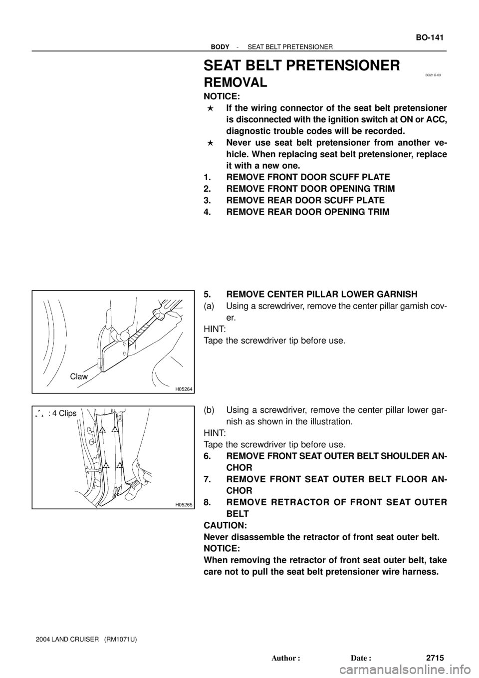
SEAT BELT PRETENSIONER
REMOVAL
NOTICE:
�If the wiring connector of the seat belt pretensioner
is disconnected with the ignition switch at ON or ACC,
diagnostic trouble codes will be recorded.
�Never use seat belt pretensioner from another ve-
hicle. When replacing seat belt pretensioner, replace
it with a new one.
1. REMOVE FRONT DOOR SCUFF PLATE
2. REMOVE FRONT DOOR OPENING TRIM
3. REMOVE REAR DOOR SCUFF PLATE
4. REMOVE REAR DOOR OPENING TRIM
5. REMOVE CENTER PILLAR LOWER GARNISH
(a) Using a screwdriver, remove the center pillar garnish cov-
er.
HINT:
Tape the screwdriver tip before use.
(b) Using a screwdriver, remove the center pillar lower gar-
nish as shown in the illustration.
HINT:
Tape the screwdriver tip before use.
6. REMOVE FRONT SEAT OUTER BELT SHOULDER AN-
CHOR
7. REMOVE FRONT SEAT OUTER BELT FLOOR AN-
CHOR
8. REMOVE RETRACTOR OF FRONT SEAT OUTER
BELT
CAUTION:
Never disassemble the retractor of front seat outer belt.
NOTICE:
When removing the retractor of front seat outer belt, take
care not to pull the seat belt pretensioner wire harness.
Page 599 of 3115

Z00030
B00807
B00808
B
A
AC2024
CORRECT WRONG
- CHARGINGCHARGING SYSTEM
CH-3
1838 Author�: Date�:
2004 LAND CRUISER (RM1071U)
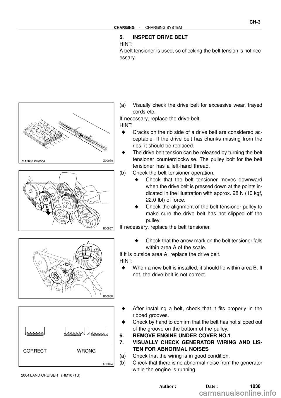
5. INSPECT DRIVE BELT
HINT:
A belt tensioner is used, so checking the belt tension is not nec-
essary.
(a) Visually check the drive belt for excessive wear, frayed
cords etc.
If necessary, replace the drive belt.
HINT:
�Cracks on the rib side of a drive belt are considered ac-
ceptable. If the drive belt has chunks missing from the
ribs, it should be replaced.
�The drive belt tension can be released by turning the belt
tensioner counterclockwise. The pulley bolt for the belt
tensioner has a left-hand thread.
(b) Check the belt tensioner operation.
�Check that the belt tensioner moves downward
when the drive belt is pressed down at the points in-
dicated in the illustration with approx. 98 N (10 kgf,
22.0 lbf) of force.
�Check the alignment of the belt tensioner pulley to
make sure the drive belt has not slipped off the
pulley.
If necessary, replace the belt tensioner.
�Check that the arrow mark on the belt tensioner falls
within area A of the scale.
If it is outside area A, replace the drive belt.
HINT:
�When a new belt is installed, it should lie within area B. If
not, the drive belt is not correct.
�After installing a belt, check that it fits properly in the
ribbed grooves.
�Check by hand to confirm that the belt has not slipped out
of the groove on the bottom of the pulley.
6. REMOVE ENGINE UNDER COVER NO.1
7. VISUALLY CHECK GENERATOR WIRING AND LIS-
TEN FOR ABNORMAL NOISES
(a) Check that the wiring is in good condition.
(b) Check that there is no abnormal noise from the generator
while the engine is running.
Page 764 of 3115
F17763
EXI
WT A43
A43 IX1
F15Cowl Side J/B RH
Cowl Side J/B RH Cowl Side J/B RH
Cowl Side J/B LHI18
Ignition SW
Engine Room J/BCombination MeterABS & BA & TRAC
& VSC ECU
SB
D4
Detection SW
(Center Diff. Lock)
2
W-B
P-B
SB
SB
SB MET1
2
47
3E3Q
56 3
3Q
3B
3Q3B J4
J/C
B-R B-R
A
AP-B
L-R
W-R AM2 IG2
76
41 10
2E 2A
1
9
1C1B
2 B-G
ECFL Block
Battery MAIN
EC BR W-R8IX1
VSC OFF
17
C13 C12 C151
103
7
14 26
AM2 DI-624
- DIAGNOSTICSABS & VEHICLE STABILITY CONTROL (VSC) &
BRAKE ASSIST (BA) SYSTEM
817 Author�: Date�:
2004 LAND CRUISER (RM1071U)
DTC Always ON Malfunction in ECU
VSC TRAC Warning Light Circuit
CIRCUIT DESCRIPTION
Always ONThere is a malfunction in the ECU internal circuit.
�Power source circuit
�Skid control ECU
�VSC TRAC warning light circuit
HINT:
If the fail safe function is activated in the VSC system, ºVSC OFFº indicator light lights up.
WIRING DIAGRAM
DICA4-01
Page 767 of 3115
F17718F18533
ABS & BA & TRAC
& VSC ECU
Engine Room J/B Combination Meter
Cowl Side J/B RH
Cowl Side J/B LH
I18
Ignition SW
Cowl Side J/B RHWA 1
A42 4
3A 5
3Q 12
C12
41
2E10
2A
1B91
1C AM2
W-RB-R
C12
C15
ECSB
BR8
IX1 3Q SB7MET
4
3EB-R
B-G
FL Block SB R-L
W-R
76AM2 IG2
J4
J/C
AA
2
F15Battery 1 10
MAIN ABS
- DIAGNOSTICSABS & VEHICLE STABILITY CONTROL (VSC) &
BRAKE ASSIST (BA) SYSTEMDI-627
820 Author�: Date�:
2004 LAND CRUISER (RM1071U)
ABS Warning Light Circuit
CIRCUIT DESCRIPTION
If the ECU detects trouble, it lights the ABS warning light while at the same time prohibiting ABS control. At
this time, the ECU records a DTC in memory.
Connect terminals Tc and E
1 of the DLC1 or Tc and CG of DLC3 to make the ABS warning light blink and
output the DTC.
WIRING DIAGRAM
DICA5-02