Page 2760 of 3115

RS0VQ-01
H20950
RS-94
- SUPPLEMENTAL RESTRAINT SYSTEMSEAT POSITION SENSOR ASSEMBLY
2369 Author�: Date�:
2004 LAND CRUISER (RM1071U)
INSTALLATION
NOTICE:
�Never use SRS parts from another vehicle. When re-
placing parts, replace them with new ones.
�Never reuse the seat position sensor assembly in-
volved in a collision when the airbag has deployed.
�Never repair a sensor in order to reuse it.
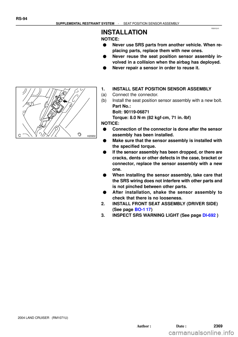
1. INSTALL SEAT POSITION SENSOR ASSEMBLY
(a) Connect the connector.
(b) Install the seat position sensor assembly with a new bolt.
Part No.:
Bolt: 90119-06871
Torque: 8.0 N´m (82 kgf´cm, 71 in.´lbf)
NOTICE:
�Connection of the connector is done after the sensor
assembly has been installed.
�Make sure that the sensor assembly is installed with
the specified torque.
�If the sensor assembly has been dropped, or there are
cracks, dents or other defects in the case, bracket or
connector, replace the sensor assembly with a new
one.
�When installing the sensor assembly, take care that
the SRS wiring does not interfere with other parts and
is not pinched between other parts.
�After installation, shake the sensor assembly to
check that there is no looseness.
2. INSTALL FRONT SEAT ASSEMBLY (DRIVER SIDE)
(See page BO-1 17)
3. INSPECT SRS WARNING LIGHT (See page DI-692)
Page 2761 of 3115
RS0VP-01
H20950
- SUPPLEMENTAL RESTRAINT SYSTEMSEAT POSITION SENSOR ASSEMBLY
RS-91
2366 Author�: Date�:
2004 LAND CRUISER (RM1071U)
REMOVAL
NOTICE:
�Do not open the cover or the case of the ECU and vari-
ous electrical devices unless absolutely necessary.
(If the IC terminals are touched, the IC may be de-
stroyed by static electricity.)
�If the wiring connector of the SRS is disconnected
and the ignition switch is at ON position, DTCs will be
recorded.
1. REMOVE FRONT SEAT ASSEMBLY (DRIVER SIDE)
(See page BO-105)
2. REMOVE SEAT POSITION SENSOR ASSEMBLY
(a) Remove the bolt and seat position sensor assembly.
(b) Disconnect the connector.
Page 3063 of 3115

SA-2
- SUSPENSION AND AXLETROUBLESHOOTING
1952 Author�: Date�:
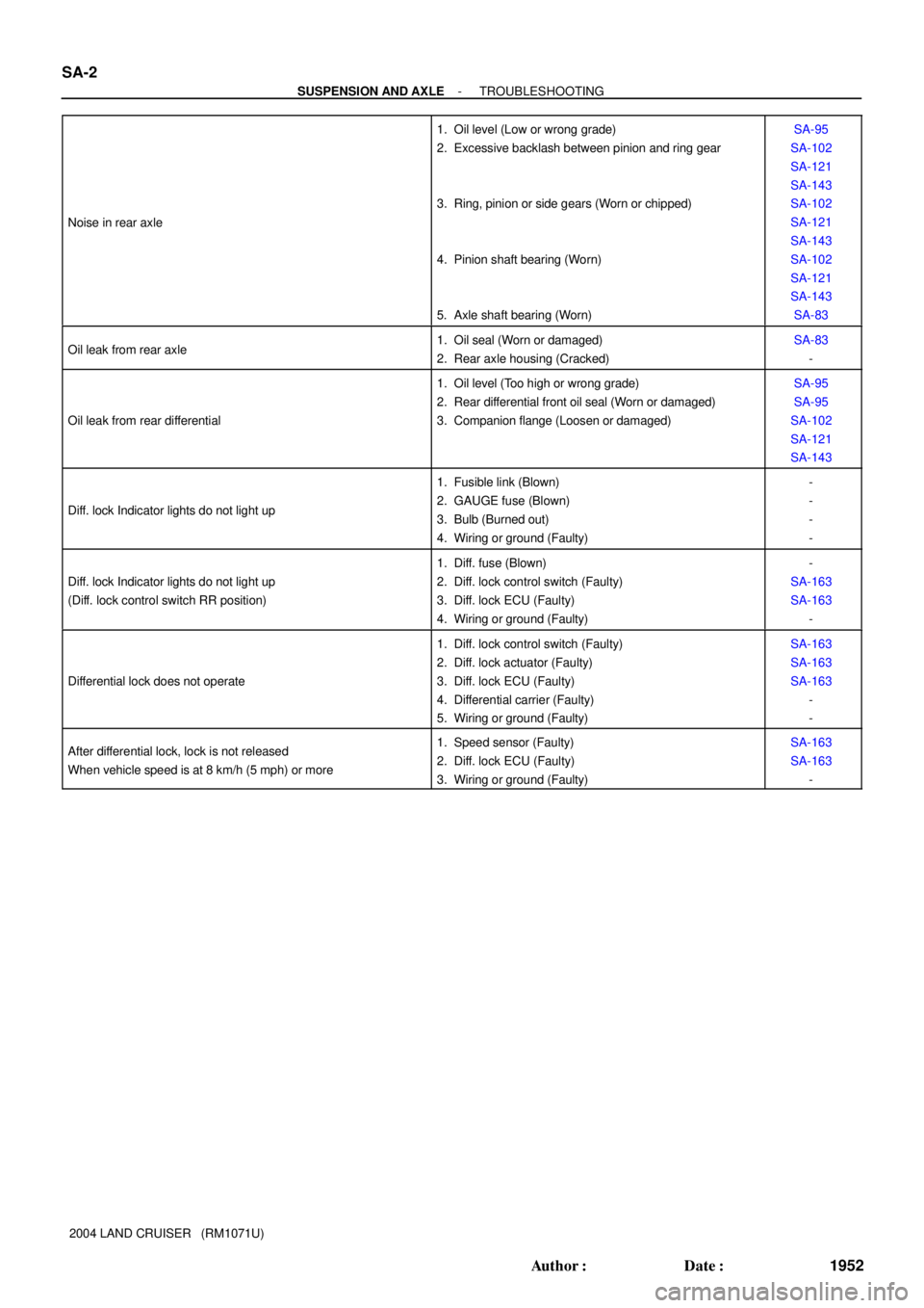
2004 LAND CRUISER (RM1071U) Noise in rear axle
1. Oil level (Low or wrong grade)
2. Excessive backlash between pinion and ring gear
3. Ring, pinion or side gears (Worn or chipped)
4. Pinion shaft bearing (Worn)
5. Axle shaft bearing (Worn)SA-95
SA-102
SA-121
SA-143
SA-102
SA-121
SA-143
SA-102
SA-121
SA-143
SA-83
Oil leak from rear axle1. Oil seal (Worn or damaged)
2. Rear axle housing (Cracked)SA-83
-
Oil leak from rear differential
1. Oil level (Too high or wrong grade)
2. Rear differential front oil seal (Worn or damaged)
3. Companion flange (Loosen or damaged)SA-95
SA-95
SA-102
SA-121
SA-143
Diff. lock Indicator lights do not light up
1. Fusible link (Blown)
2. GAUGE fuse (Blown)
3. Bulb (Burned out)
4. Wiring or ground (Faulty)-
-
-
-
Diff. lock Indicator lights do not light up
(Diff. lock control switch RR position)
1. Diff. fuse (Blown)
2. Diff. lock control switch (Faulty)
3. Diff. lock ECU (Faulty)
4. Wiring or ground (Faulty)-
SA-163
SA-163
-
Differential lock does not operate
1. Diff. lock control switch (Faulty)
2. Diff. lock actuator (Faulty)
3. Diff. lock ECU (Faulty)
4. Differential carrier (Faulty)
5. Wiring or ground (Faulty)SA-163
SA-163
SA-163
-
-
After differential lock, lock is not released
When vehicle speed is at 8 km/h (5 mph) or more1. Speed sensor (Faulty)
2. Diff. lock ECU (Faulty)
3. Wiring or ground (Faulty)SA-163
SA-163
-
Page 3115 of 3115
TR06Z-02
F08168
Transfer Shift Lever Assembly
Transfer Shift Lever Rod
Assembly Plate Washer
Clip Wave Washer
Bushing
Bushing
� Gasket
Snap RingWave Washer
Plate Washer
Transfer Shift Lever
BootWiring Harness Clamp Bracket
Transfer Shift Lever Boot
Transfer Control Shift Lever Retainer
� Gasket
19 (190, 14)
14 (140, 10)
N´m (kgf´cm, ft´lbf) : Specified torque
� Non-reusable part
Apply MP grease
- TRANSFERTRANSFER SHIFT LEVER ASSEMBLY
TR-47
1935 Author�: Date�:
2004 LAND CRUISER (RM1071U)
TRANSFER SHIFT LEVER ASSEMBLY
COMPONENTS