Page 943 of 1659
Oil Pressure Check
WARNING:
lBe careful not to burn yourself, as the engine and oil
may be hot.
lPut gearshift lever in Neutral N position.
1. Check oil level.
2. Remove oil pressure switch.
3. Install pressure gauge.
4. Start engine and warm it up to normal operating temperature.
5. Check oil pressure with engine running under no-load.
Engine speed
rpmApproximate discharge pressure
kPa (bar, kg/cm2, psi)
Idle speed More than 78 (0.78, 0.8, 11)
3,000 412 - 481 (4.12 - 4.81, 4.2 - 4.9, 60 - 70)
lIf difference is extreme, check oil passage and oil pump
for oil leaks.
6. Install oil pressure switch with sealant.
Oil Pump
SLC183A
SLC770A
SLC229B
ENGINE LUBRICATION SYSTEMKA
LC-4
Page 945 of 1659
Cooling Circuit
System Check
WARNING:
Never remove the radiator cap when the engine is hot. Seri-
ous burns could occur from high pressure coolant escaping
from the radiator.
Wrap a thick cloth around the cap. Slowly turn it a quarter
turn to allow built-up pressure to escape. Carefully remove
the cap by turning it all the way.
CHECKING COOLING SYSTEM HOSES
Check hoses for the following:
lImproper attachment
lLeaks
lCracks
lDamage
lChafing
lDeterioration
SLC138B
ENGINE COOLING SYSTEMKA
LC-6
Page 950 of 1659
INSPECTION
Check fan coupling for rough operation, wobbling, oil leakage or
bent bimetal.
After assembly, verify the fan does not wobble or flap while the
engine is running.
WARNING:
lWhen the engine is running, keep hands and clothing
away from moving parts such as drive belts and fan.
Refilling engine coolant
For details on refilling engine coolant, refer to MA section
(``Changing Engine Coolant'', ``ENGINE MAINTENANCE'').
SLC072
SLC151B
ENGINE COOLING SYSTEMKA
Cooling Fan (Crankshaft driven) (Cont'd)
LC-11
Page 952 of 1659
Oil Pressure Check (On-vehicle service)
WARNING:
lBe careful not to burn yourself, as the engine and oil
may be hot.
lOil pressure check should be done in ``Neutral'' gear
position.
1. Check oil level.
2. Disconnect oil pressure switch harness connector.
3. Remove oil pressure switch.
4. Install pressure gauge and hose.
5. Start engine and warm it up to normal operating temperature.
6. Check oil pressure with engine running under no-load.
Engine speed
rpmApproximate discharge pressure
kPa (bar, kg/cm2, psi)
Idle speed More than 78 (0.78, 0.8, 11)
3,000294 - 392
(2.94 - 3.92, 3.0 - 4.0, 43 - 57)
If difference is extreme, check oil passage and oil pump for
oil leaks.
7. Install oil pressure switch with sealant.
Oil pressure switch:
:10-13Nzm (1.0 - 1.3 kg-m, 87 - 113 in-lb)
DLC013
DLC002
ENGINE LUBRICATION SYSTEMTD
LC-13
Page 959 of 1659

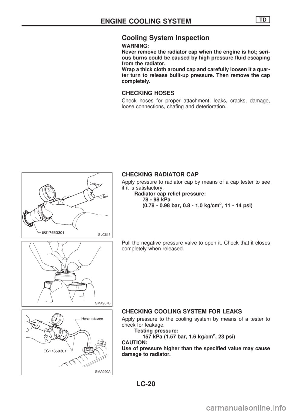
Cooling System Inspection
WARNING:
Never remove the radiator cap when the engine is hot; seri-
ous burns could be caused by high pressure fluid escaping
from the radiator.
Wrap a thick cloth around cap and carefully loosen it a quar-
ter turn to release built-up pressure. Then remove the cap
completely.
CHECKING HOSES
Check hoses for proper attachment, leaks, cracks, damage,
loose connections, chafing and deterioration.
CHECKING RADIATOR CAP
Apply pressure to radiator cap by means of a cap tester to see
if it is satisfactory.
Radiator cap relief pressure:
78-98kPa
(0.78 - 0.98 bar, 0.8 - 1.0 kg/cm
2, 11 - 14 psi)
Pull the negative pressure valve to open it. Check that it closes
completely when released.
CHECKING COOLING SYSTEM FOR LEAKS
Apply pressure to the cooling system by means of a tester to
check for leakage.
Testing pressure:
157 kPa (1.57 bar, 1.6 kg/cm
2, 23 psi)
CAUTION:
Use of pressure higher than the specified value may cause
damage to radiator.
SLC613
SMA967B
SMA990A
ENGINE COOLING SYSTEMTD
LC-20
Page 960 of 1659
Water Pump and Cooling Fan (Camshaft
driven)
REMOVAL AND INSTALLATION
Drain coolant from drain plugs on cylinder block and radiator.
Cylinder block drain plug
(Use proper sealant):
:20-29Nzm (2.0 - 3.0 kg-m, 14 - 22 ft-lb)
CAUTION:
lWhen removing water pump assembly, be careful not to
get coolant on drive belt.
lWater pump cannot be disassembled and should be
replaced as a unit.
lAlways replace with new gasket.
lAfter assembly, verify the fan does not wobble or flap
while the engine is running.
lAfter installing water pump, connect hose and clamp
securely, then check for leaks using radiator cap tester.
WARNING:
When the engine is running, keep hands and clothing away
from moving parts such as drive belts and fan.
SMA617C
SLC978-A
ENGINE COOLING SYSTEMTD
LC-21
Page 969 of 1659
lUse pliers in the locations where Tool cannot be used.
4. Make sure that the rim is completely crimped down.
Standard height ``H'':
8.0 - 8.4 mm (0.315 - 0.331 in)
5. Confirm that there is no leakage.
Refer to Inspection.
INSPECTION
1. Apply pressure with Tool.
Specified pressure value:
157 kPa (1.57 bar, 1.6 kg/cm
2, 23 psi)
WARNING:
To prevent the risk of the hose coming undone while under
pressure, securely fasten it down with a hose clamp.
2. Check for leakage.
SLC896
SLC897
SLC554A
SLC933
SLC934
ENGINE COOLING SYSTEM
Radiator (Aluminum type) (Cont'd)
LC-30
Page 974 of 1659

Supplemental Restraint System (SRS) ``AIR
BAG'' (4WD models)
The Supplemental Restraint System ``AIR BAG'', used along with a seat belt, helps to reduce the risk or
severity of injury to the driver in a frontal collision. The Supplemental Restraint System consists of air bag
module (located in the center of the steering wheel), a diagnosis sensor unit, warning lamp, wiring harness
and spiral cable. Information necessary to service the system safely is included in theRS sectionof this
Service Manual.
WARNING:
lTo avoid rendering the SRS inoperative, which could increase the risk of personal injury or death
in the event of a collision which would result in air bag inflation, all maintenance must be per-
formed by an authorized NISSAN dealer.
lImproper maintenance, including incorrect removal and installation of the SRS, can lead to per-
sonal injury caused by unintentional activation of the system.
lDo not use electrical test equipment on any circuit related to the SRS unless instructed to in this
Service Manual. SRS wiring harnesses are covered with yellow insulation either just before the
harness connectors or for the complete harness, for easy identification.
Supplemental Restraint System (SRS) ``AIR
BAG'' (2WD models)
The Supplemental Restraint System ``AIR BAG'', used along with a seat belt, helps to reduce the risk or
severity of injury to the driver in a frontal collision. The Supplemental Restraint System consists of an air
bag module (located in the center of the steering wheel), a diagnosis sensor unit, warning lamp, wiring har-
ness and spiral cable. Information necessary to service the system safely is included in theRS sectionof
this Service Manual.
WARNING:
lTo avoid rendering the SRS inoperative, which could increase the risk of personal injury or death
in the event of a collision which would result in air bag inflation, all maintenance must be per-
formed by an authorized NISSAN dealer.
lImproper maintenance, including incorrect removal and installation of the SRS, can lead to per-
sonal injury caused by unintentional activation of the system.
lDo not use electrical test equipment on any circuit related to the SRS.
PRECAUTIONS AND PREPARATION
MA-1