1998 NISSAN PICK-UP warning
[x] Cancel search: warningPage 1201 of 1659
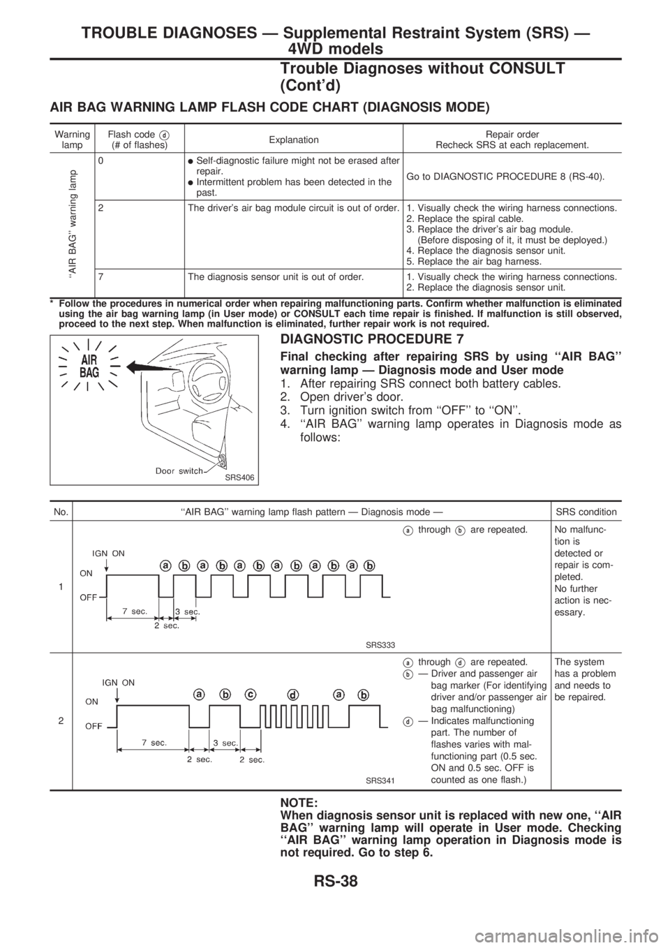
AIR BAG WARNING LAMP FLASH CODE CHART (DIAGNOSIS MODE)
Warning
lampFlash codeVd(# of flashes)ExplanationRepair order
Recheck SRS at each replacement.
``AIR BAG'' warning lamp
0lSelf-diagnostic failure might not be erased after
repair.
lIntermittent problem has been detected in the
past.Go to DIAGNOSTIC PROCEDURE 8 (RS-40).
2 The driver's air bag module circuit is out of order. 1. Visually check the wiring harness connections.
2. Replace the spiral cable.
3. Replace the driver's air bag module.
(Before disposing of it, it must be deployed.)
4. Replace the diagnosis sensor unit.
5. Replace the air bag harness.
7 The diagnosis sensor unit is out of order. 1. Visually check the wiring harness connections.
2. Replace the diagnosis sensor unit.
* Follow the procedures in numerical order when repairing malfunctioning parts. Confirm whether malfunction is eliminated
using the air bag warning lamp (in User mode) or CONSULT each time repair is finished. If malfunction is still observed,
proceed to the next step. When malfunction is eliminated, further repair work is not required.
DIAGNOSTIC PROCEDURE 7
Final checking after repairing SRS by using ``AIR BAG''
warning lamp Ð Diagnosis mode and User mode
1. After repairing SRS connect both battery cables.
2. Open driver's door.
3. Turn ignition switch from ``OFF'' to ``ON''.
4. ``AIR BAG'' warning lamp operates in Diagnosis mode as
follows:
No. ``AIR BAG'' warning lamp flash pattern Ð Diagnosis mode Ð SRS condition
1
SRS333
VathroughVbare repeated. No malfunc-
tion is
detected or
repair is com-
pleted.
No further
action is nec-
essary.
2
SRS341
VathroughVdare repeated.
VbÐ Driver and passenger air
bag marker (For identifying
driver and/or passenger air
bag malfunctioning)
VdÐ Indicates malfunctioning
part. The number of
flashes varies with mal-
functioning part (0.5 sec.
ON and 0.5 sec. OFF is
counted as one flash.)The system
has a problem
and needs to
be repaired.
NOTE:
When diagnosis sensor unit is replaced with new one, ``AIR
BAG'' warning lamp will operate in User mode. Checking
``AIR BAG'' warning lamp operation in Diagnosis mode is
not required. Go to step 6.
SRS406
TROUBLE DIAGNOSES Ð Supplemental Restraint System (SRS) Ð
4WD models
Trouble Diagnoses without CONSULT
(Cont'd)
RS-38
Page 1202 of 1659
5. If ``AIR BAG'' warning lamp operates as shown in No. 1 in
chart above, turn ignition switch ``OFF'' to reset from Diag-
nosis mode to User mode and to erase the memory of the
malfunction. Then go to step 6.
If ``AIR BAG'' warning lamp operates as shown in No. 2 or
No. 3 in chart above, the malfunctioning part is not repaired
completely, or another malfunctioning part is detected. Go to
DIAGNOSTIC PROCEDURE 6, page RS-37, and repair mal-
functioning part completely.
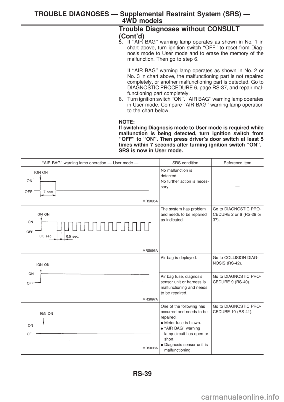
6. Turn ignition switch ``ON''. ``AIR BAG'' warning lamp operates
in User mode. Compare ``AIR BAG'' warning lamp operation
to the chart below.
NOTE:
If switching Diagnosis mode to User mode is required while
malfunction is being detected, turn ignition switch from
``OFF'' to ``ON''. Then press driver's door switch at least 5
times within 7 seconds after turning ignition switch ``ON''.
SRS is now in User mode.
``AIR BAG'' warning lamp operation Ð User mode Ð SRS condition Reference item
MRS095A
No malfunction is
detected.
No further action is neces-
sary.Ð
MRS096A
The system has problem
and needs to be repaired
as indicated.Go to DIAGNOSTIC PRO-
CEDURE 2 or 6 (RS-29 or
37).
MRS097A
Air bag is deployed. Go to COLLISION DIAG-
NOSIS (RS-42).
Air bag fuse, diagnosis
sensor unit or harness is
malfunctioning and needs
to be repaired.Go to DIAGNOSTIC PRO-
CEDURE 9 (RS-40).
MRS098A
One of the following has
occurred and needs to be
repaired.
lMeter fuse is blown.
l``AIR BAG'' warning
lamp circuit has open or
short.
lDiagnosis sensor unit is
malfunctioning.Go to DIAGNOSTIC PRO-
CEDURE 10 (RS-41).
TROUBLE DIAGNOSES Ð Supplemental Restraint System (SRS) Ð
4WD models
Trouble Diagnoses without CONSULT
(Cont'd)
RS-39
Page 1203 of 1659
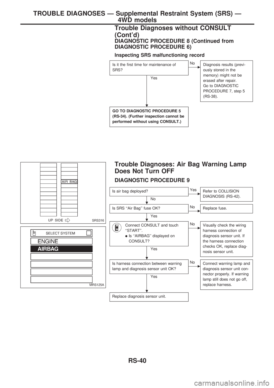
DIAGNOSTIC PROCEDURE 8 (Continued from
DIAGNOSTIC PROCEDURE 6)
Inspecting SRS malfunctioning record
Is it the first time for maintenance of
SRS?
Yes
cNo
Diagnosis results (previ-
ously stored in the
memory) might not be
erased after repair.
Go to DIAGNOSTIC
PROCEDURE 7, step 5
(RS-38).
GO TO DIAGNOSTIC PROCEDURE 5
(RS-34). (Further inspection cannot be
performed without using CONSULT.)
Trouble Diagnoses: Air Bag Warning Lamp
Does Not Turn OFF
DIAGNOSTIC PROCEDURE 9
Is air bag deployed?
No
cYes
Refer to COLLISION
DIAGNOSIS (RS-42).
Is SRS ``Air Bag'' fuse OK?
Yes
cNo
Replace fuse.
Connect CONSULT and touch
``START''.
lIs ``AIRBAG'' displayed on
CONSULT?
Yes
cNo
Visually check the wiring
harness connection of
diagnosis sensor unit. If
the harness connection
checks OK, replace diag-
nosis sensor unit.
Is harness connection between warning
lamp and diagnosis sensor unit OK?
Yes
cNo
Connect warning lamp and
diagnosis sensor unit con-
nector properly. If warning
lamp still does not go off,
replace harness.
Replace diagnosis sensor unit.
SRS316
MRS125A
.
.
.
.
.
TROUBLE DIAGNOSES Ð Supplemental Restraint System (SRS) Ð
4WD models
Trouble Diagnoses without CONSULT
(Cont'd)
RS-40
Page 1204 of 1659
Trouble Diagnoses: Air Bag Warning Lamp
Does Not Turn ON
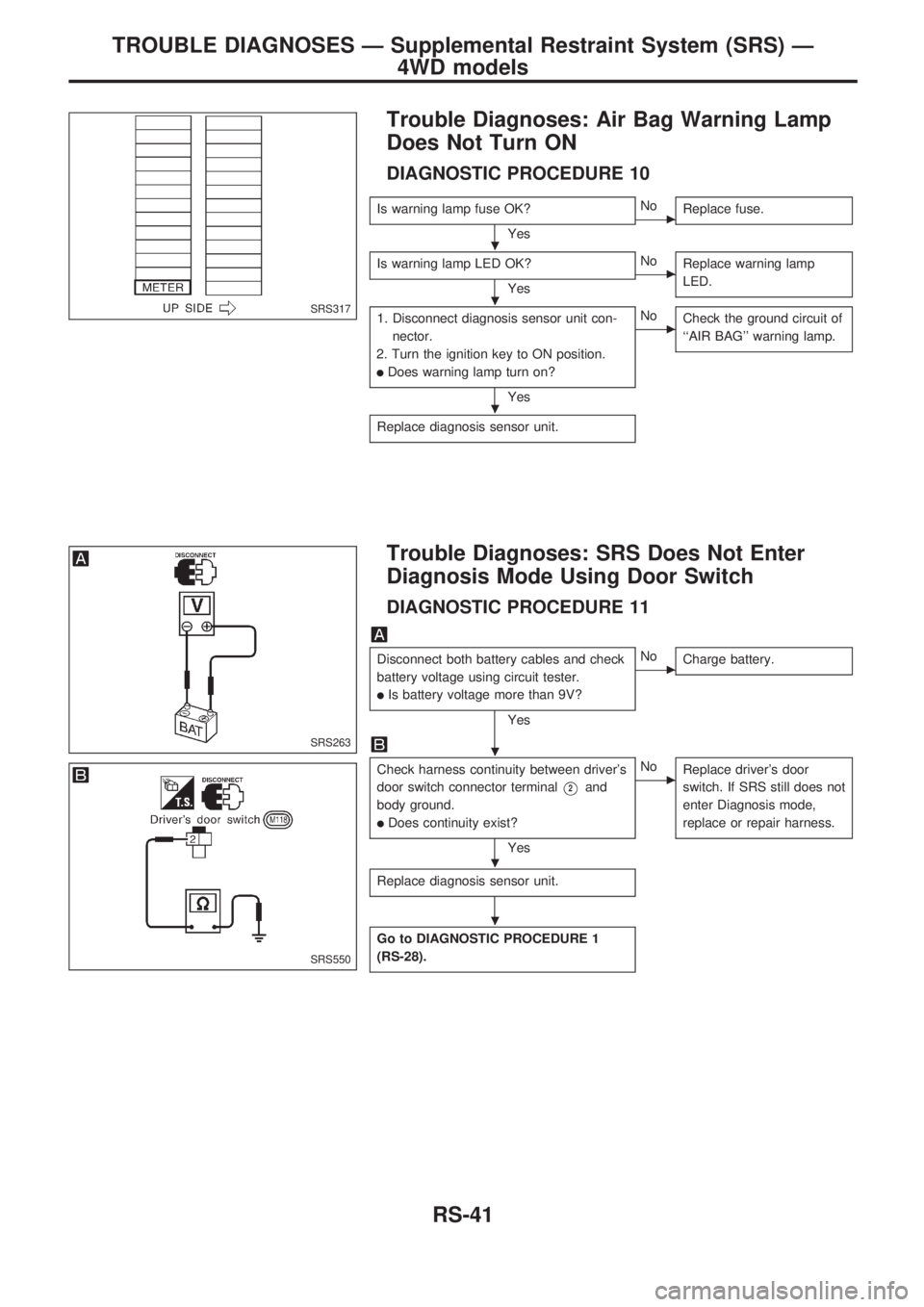
DIAGNOSTIC PROCEDURE 10
Is warning lamp fuse OK?
YescNo
Replace fuse.
Is warning lamp LED OK?
YescNo
Replace warning lamp
LED.
1. Disconnect diagnosis sensor unit con-
nector.
2. Turn the ignition key to ON position.
lDoes warning lamp turn on?
Yes
cNo
Check the ground circuit of
``AIR BAG'' warning lamp.
Replace diagnosis sensor unit.
Trouble Diagnoses: SRS Does Not Enter
Diagnosis Mode Using Door Switch
DIAGNOSTIC PROCEDURE 11
Disconnect both battery cables and check
battery voltage using circuit tester.
lIs battery voltage more than 9V?
Yes
cNo
Charge battery.
Check harness continuity between driver's
door switch connector terminal
V2and
body ground.
lDoes continuity exist?
Yes
cNo
Replace driver's door
switch. If SRS still does not
enter Diagnosis mode,
replace or repair harness.
Replace diagnosis sensor unit.
Go to DIAGNOSTIC PROCEDURE 1
(RS-28).
SRS317
SRS263
SRS550
.
.
.
.
.
.
TROUBLE DIAGNOSES Ð Supplemental Restraint System (SRS) Ð
4WD models
RS-41
Page 1205 of 1659

FOR FRONTAL COLLISION
To repair the SRS for a frontal collision, perform the following steps.
When SRS is activated in a collision:
V1Replace the diagnosis sensor unit.
V2Remove the air bag module.
V3Check the SRS components using the table shown below:
lReplace any SRS components showing visible signs of damage (dents, cracks, deformation).
V4Install new air bag module.
V5Conduct self-diagnosis using CONSULT, and ``AIR BAG'' warning lamp. Refer to ``Self-diagnosis'' for
details (RS-28). Ensure entire SRS operates properly.
When SRS is not activated in a collision:
V1Check the SRS components using the table shown below:
lReplace any SRS components showing visible signs of damage (dents, cracks, deformation).
V2Conduct self-diagnosis using CONSULT, and ``AIR BAG'' warning lamp. Refer to ``Self-diagnosis'' for
details (RS-28). Ensure entire SRS operates properly.
SRS inspection
Part SRS is activated SRS is NOT activated
Air bag module REPLACE
Install air bag mod-
ule with new bolts.1. Remove air bag module. Check harness cover and connectors for damage, ter-
minals for deformities, and harness for binding.
2. Install driver air bag module into the steering wheel to check fit and alignment
with the wheel.
3. No damage found, reinstall with new bolts.
4. If damagedÐREPLACE. Air bag must be deployed before discarding.
Diagnosis sensor
unitREPLACE
Install diagnosis sen-
sor unit with new
bolts.1. Check case and bracket for dents, cracks or deformities.
2. Check connectors for damage, and terminals for deformities.
3. If no damage is found, reinstall with new bolts.
4. If damagedÐREPLACE. Install diagnosis sensor unit with new bolts.
Steering wheel 1. Visually check steering wheel for deformities.
2. Check harness (built into steering wheel) and connectors for damage, and terminals for deformities.
3. Install air bag module to check fit or alignment with steering wheel.
4. Check steering wheel for excessive free play.
5. If no damage is found, reinstall.
6. If damagedÐREPLACE.
Spiral cable 1. Visually check spiral cable and combination switch for damage.
2. Check connectors, lead wires and protective tape for damage.
3. Check steering wheel for noise, binding or heavy operation.
4. If no damage is found, reinstall it.
5. If damagedÐREPLACE.
Harness and Con-
nectors1. Check connectors for poor connection, damage, and terminals for deformities.
2. Check harness for binding, chafing, cuts, or deformities.
3. If no damage is found, reinstall harness and connectors.
4. DamagedÐREPLACE damaged section of harness. Do not attempt to repair, splice or modify any SRS
harness.
COLLISION DIAGNOSIS Ð 4WD models
RS-42
Page 1223 of 1659
Supplemental Restraint System (SRS) ``AIR
BAG'' (4WD models)
The Supplemental Restraint System ``Air Bag'', used along with a seat belt, helps to reduce the risk or
severity of injury to the driver in a frontal collision. The Supplemental Restraint System consists of an air
bag module (located in the center of the steering wheel), a diagnosis sensor unit, warning lamp, wiring har-
ness and spiral cable. Information necessary to service the system safely is included in theRS sectionof
this Service Manual.
WARNING:
lTo avoid rendering the SRS inoperative, which could increase the risk of personal injury or death
in the event of a collision which would result in air bag inflation, all maintenance must be per-
formed by an authorized NISSAN dealer.
lImproper maintenance, including incorrect removal and installation of the SRS, can lead to per-
sonal injury caused by unintentional activation of the system.
lDo not use electrical test equipment on any circuit related to the SRS unless instructed to in this
Service Manual. SRS wiring harnesses are covered with yellow insulation either just before the
harness connectors or for the complete harness, for easy identification.
Supplemental Restraint System (SRS) ``AIR
BAG'' (2WD models)
The Supplemental Restraint System ``Air Bag'', used along with a seat belt, helps to reduce the risk or
severity of injury to the driver in a frontal collision. The Supplemental Restraint System consists of an air
bag module (located in the center of the steering wheel), a diagnosis sensor unit, warning lamp and spiral
cable. Information necessary to service the system safely is included in theRS sectionof this Service
Manual.
WARNING:
lTo avoid rendering the SRS inoperative, which could increase the risk of personal injury or death
in the event of a collision which would result in air bag inflation, all maintenance must be per-
formed by an authorized NISSAN dealer.
lImproper maintenance, including incorrect removal and installation of the SRS, can lead to per-
sonal injury caused by unintentional activation of the system.
lDo not use electrical test equipment on any circuit related to the SRS.
Precautions for Steering System
lBefore disassembly, thoroughly clean the outside of the unit.
lDisassembly should be done in a clean work area. It is important to prevent the internal parts
from becoming contaminated by dirt or other foreign matter.
lFor easier and proper assembly, place disassembled parts in order on a parts rack.
lUse nylon cloths or paper towels to clean the parts; common shop rags can leave lint that might
interfere with their operation.
lBefore inspection or reassembly, carefully clean all parts with a general purpose, non-flammable
solvent.
lBefore assembly, apply a coat of recommended ATF* to hydraulic parts. Petroleum jelly may be
applied to O-rings and seals. Do not use any grease.
lReplace all gaskets, seals and O-rings. Avoid damaging O-rings, seals and gaskets during instal-
lation. Perform functional tests whenever designated.
*: Automatic Transmission Fluid type DEXRON
TMII E, DEXRONTMIII, or equivalent.
PRECAUTIONS AND PREPARATION
ST-1
Page 1229 of 1659
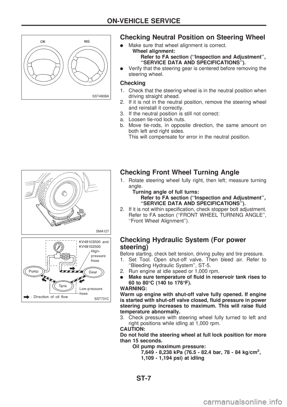
Checking Neutral Position on Steering Wheel
lMake sure that wheel alignment is correct.
Wheel alignment:
Refer to FA section (``Inspection and Adjustment'',
``SERVICE DATA AND SPECIFICATIONS'').
lVerify that the steering gear is centered before removing the
steering wheel.
Checking
1. Check that the steering wheel is in the neutral position when
driving straight ahead.
2. If it is not in the neutral position, remove the steering wheel
and reinstall it correctly.
3. If the neutral position is still not correct:
a. Loosen tie-rod lock nuts.
b. Move tie-rods, in opposite direction, the same amount on
both left and right sides.
This will compensate for error in the neutral position.
Checking Front Wheel Turning Angle
1. Rotate steering wheel fully right, then left; measure turning
angle.
Turning angle of full turns:
Refer to FA section (``Inspection and Adjustment'',
``SERVICE DATA AND SPECIFICATIONS'').
2. If it is not within specification, check stopper bolt adjustment.
Refer to FA section (``FRONT WHEEL TURNING ANGLE'',
``Front Wheel Alignment'').
Checking Hydraulic System (For power
steering)
Before starting, check belt tension, driving pulley and tire pressure.
1. Set Tool. Open shut-off valve. Then bleed air. Refer to
``Bleeding Hydraulic System'', ST-5.
2. Run engine at idle speed or 1,000 rpm.
lMake sure temperature of fluid in reservoir tank rises to
60 to 80ÉC (140 to 176ÉF).
WARNING:
Warm up engine with shut-off valve fully opened. If engine
is started with shut-off valve closed, fluid pressure in power
steering pump increases to maximum. This will raise fluid
temperature abnormally.
3. Check pressure with steering wheel fully turned to left and
right positions while idling at 1,000 rpm.
CAUTION:
Do not hold the steering wheel at full lock position for more
than 15 seconds.
Oil pump maximum pressure:
7,649 - 8,238 kPa (76.5 - 82.4 bar, 78 - 84 kg/cm
2,
1,109 - 1,194 psi) at idling
SST490BA
SMA127
SST731C
ON-VEHICLE SERVICE
ST-7
Page 1271 of 1659
Removal
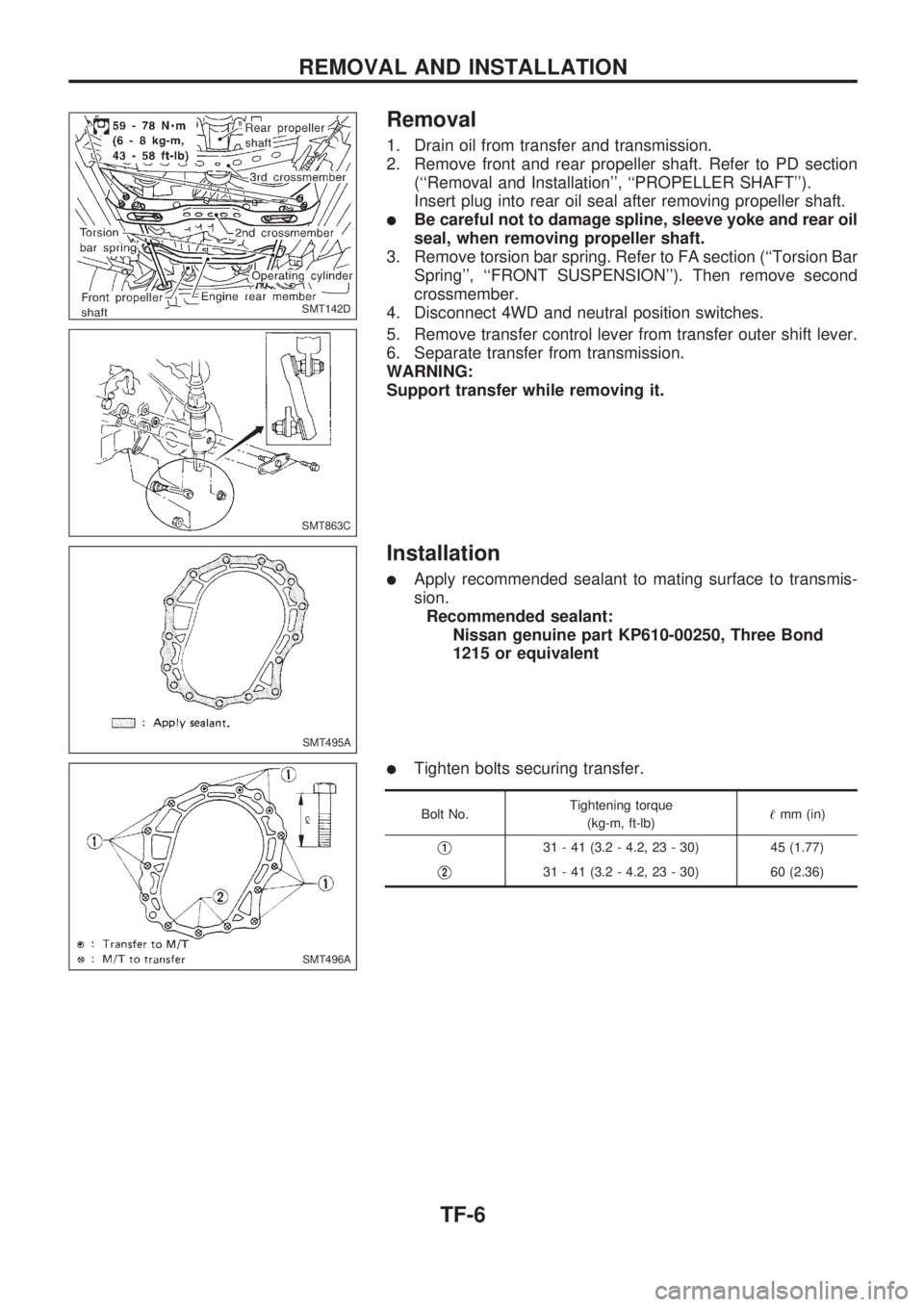
1. Drain oil from transfer and transmission.
2. Remove front and rear propeller shaft. Refer to PD section
(``Removal and Installation'', ``PROPELLER SHAFT'').
Insert plug into rear oil seal after removing propeller shaft.
lBe careful not to damage spline, sleeve yoke and rear oil
seal, when removing propeller shaft.
3. Remove torsion bar spring. Refer to FA section (``Torsion Bar
Spring'', ``FRONT SUSPENSION''). Then remove second
crossmember.
4. Disconnect 4WD and neutral position switches.
5. Remove transfer control lever from transfer outer shift lever.
6. Separate transfer from transmission.
WARNING:
Support transfer while removing it.
Installation
lApply recommended sealant to mating surface to transmis-
sion.
Recommended sealant:
Nissan genuine part KP610-00250, Three Bond
1215 or equivalent
lTighten bolts securing transfer.
Bolt No.Tightening torque
(kg-m, ft-lb)!mm (in)
V131 - 41 (3.2 - 4.2, 23 - 30) 45 (1.77)
V231 - 41 (3.2 - 4.2, 23 - 30) 60 (2.36)
SMT142D
SMT863C
SMT495A
SMT496A
REMOVAL AND INSTALLATION
TF-6