Page 1412 of 1659
HEL368A
WARNING LAMPS
Wiring Diagram Ð WARN Ð/RHD Models
(Cont'd)
EL-114
Page 1413 of 1659
HEL369A
WARNING LAMPS
Wiring Diagram Ð WARN Ð/RHD Models
(Cont'd)
EL-115
Page 1414 of 1659
Electrical Components Inspection
FUEL WARNING LAMP SENSOR CHECK
lIt will take a short time for the bulb to light.
OIL PRESSURE SWITCH CHECK
Oil pressure
kPa (bar, kg/cm2, psi)Continuity
Engine startMore than 10 - 20
(0.10 - 0.20, 0.1 - 0.2,1-3)NO
Engine stopLess than 10 - 20
(0.10 - 0.20, 0.1 - 0.2,1-3)YES
Check the continuity between the terminals of oil pressure switch
and body ground.
DIODE CHECK
lCheck continuity using an ohmmeter.
lDiode is functioning properly if test results are as shown in
the figure at left.
NOTE: Specification may vary depending on the type of
tester. Before performing this inspection, be sure to
refer to the instruction manual for the tester to be
used.
lDiodes for warning lamps are built into the combination meter
printed circuit.
GEL191
MEL425F
SEL901F
GEL192
WARNING LAMPS
EL-116
Page 1415 of 1659
Wiring diagram Ð BUZZER Ð/LHD Models
for Europe
LIGHT WARNING BUZZER
HEL370A
WARNING BUZZER
EL-117
Page 1416 of 1659
Wiring diagram Ð BUZZER Ð/RHD Models
for Europe
LIGHT WARNING BUZZER
HEL371A
WARNING BUZZER
EL-118
Page 1417 of 1659
Electrical Components Inspection
FUEL FILTER WARNING BUZZER CHECK
LIGHT WARNING BUZZER
1. Apply 12V direct current to warning buzzer unit terminalsV10
andV4.
Warning buzzer should sound.
2. Apply 12V direct current to warning buzzer unit terminals
V10,
V11andV4.
Warning buzzer should not sound.
GEL208
SEL644V
SEL645V
WARNING BUZZER
EL-119
Page 1471 of 1659

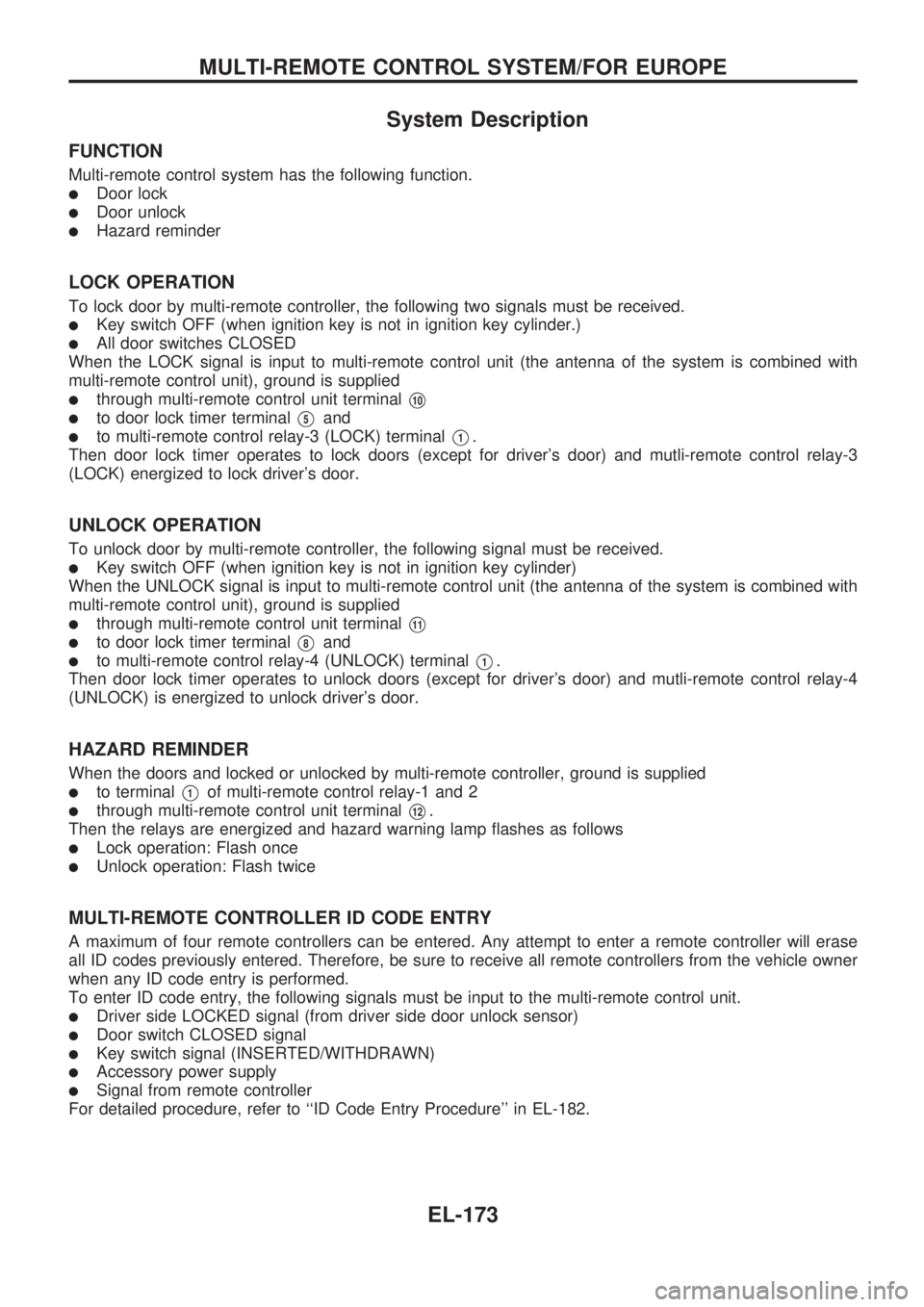
System Description
FUNCTION
Multi-remote control system has the following function.
lDoor lock
lDoor unlock
lHazard reminder
LOCK OPERATION
To lock door by multi-remote controller, the following two signals must be received.
lKey switch OFF (when ignition key is not in ignition key cylinder.)
lAll door switches CLOSED
When the LOCK signal is input to multi-remote control unit (the antenna of the system is combined with
multi-remote control unit), ground is supplied
lthrough multi-remote control unit terminalV10
lto door lock timer terminalV5and
lto multi-remote control relay-3 (LOCK) terminalV1.
Then door lock timer operates to lock doors (except for driver's door) and mutli-remote control relay-3
(LOCK) energized to lock driver's door.
UNLOCK OPERATION
To unlock door by multi-remote controller, the following signal must be received.
lKey switch OFF (when ignition key is not in ignition key cylinder)
When the UNLOCK signal is input to multi-remote control unit (the antenna of the system is combined with
multi-remote control unit), ground is supplied
lthrough multi-remote control unit terminalV11
lto door lock timer terminalV8and
lto multi-remote control relay-4 (UNLOCK) terminalV1.
Then door lock timer operates to unlock doors (except for driver's door) and mutli-remote control relay-4
(UNLOCK) is energized to unlock driver's door.
HAZARD REMINDER
When the doors and locked or unlocked by multi-remote controller, ground is supplied
lto terminalV1of multi-remote control relay-1 and 2
lthrough multi-remote control unit terminalV12.
Then the relays are energized and hazard warning lamp flashes as follows
lLock operation: Flash once
lUnlock operation: Flash twice
MULTI-REMOTE CONTROLLER ID CODE ENTRY
A maximum of four remote controllers can be entered. Any attempt to enter a remote controller will erase
all ID codes previously entered. Therefore, be sure to receive all remote controllers from the vehicle owner
when any ID code entry is performed.
To enter ID code entry, the following signals must be input to the multi-remote control unit.
lDriver side LOCKED signal (from driver side door unlock sensor)
lDoor switch CLOSED signal
lKey switch signal (INSERTED/WITHDRAWN)
lAccessory power supply
lSignal from remote controller
For detailed procedure, refer to ``ID Code Entry Procedure'' in EL-182.
MULTI-REMOTE CONTROL SYSTEM/FOR EUROPE
EL-173
Page 1480 of 1659

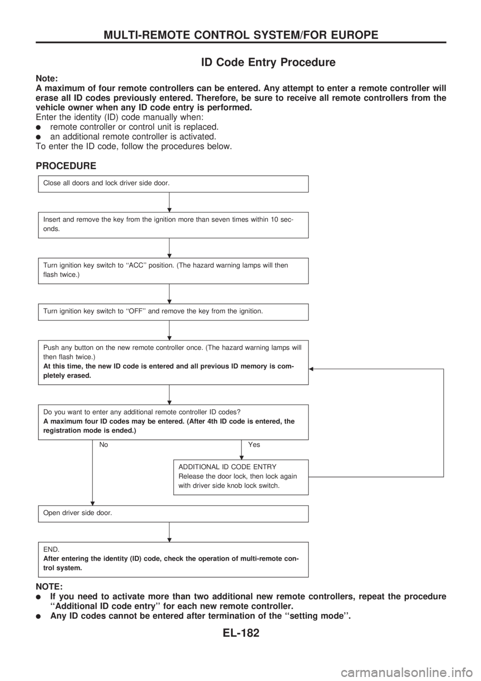
ID Code Entry Procedure
Note:
A maximum of four remote controllers can be entered. Any attempt to enter a remote controller will
erase all ID codes previously entered. Therefore, be sure to receive all remote controllers from the
vehicle owner when any ID code entry is performed.
Enter the identity (ID) code manually when:
lremote controller or control unit is replaced.
lan additional remote controller is activated.
To enter the ID code, follow the procedures below.
PROCEDURE
Close all doors and lock driver side door.
Insert and remove the key from the ignition more than seven times within 10 sec-
onds.
Turn ignition key switch to ``ACC'' position. (The hazard warning lamps will then
flash twice.)
Turn ignition key switch to ``OFF'' and remove the key from the ignition.
Push any button on the new remote controller once. (The hazard warning lamps will
then flash twice.)
At this time, the new ID code is entered and all previous ID memory is com-
pletely erased.
b
Do you want to enter any additional remote controller ID codes?
A maximum four ID codes may be entered. (After 4th ID code is entered, the
registration mode is ended.)
No Yes
ADDITIONAL ID CODE ENTRY
Release the door lock, then lock again
with driver side knob lock switch.
Open driver side door.
END.
After entering the identity (ID) code, check the operation of multi-remote con-
trol system.
NOTE:
lIf you need to activate more than two additional new remote controllers, repeat the procedure
``Additional ID code entry'' for each new remote controller.
lAny ID codes cannot be entered after termination of the ``setting mode''.
.
.
.
.
.
.
.
.
MULTI-REMOTE CONTROL SYSTEM/FOR EUROPE
EL-182