1998 NISSAN PICK-UP warning
[x] Cancel search: warningPage 1028 of 1659
Removal
2WD MODEL
1. Remove battery negative terminal and starter motor. Refer to
EL section (``Removal and Installation'', ``STARTING SYS-
TEM'').
2. Remove transmission shift knob, dust rubber boot, hole
cover and transmission shift lever.
3. Remove propeller shaft. Refer to PD section (``Removal and
Installation'', ``PROPELLER SHAFT'').
4. Remove exhaust tube.
5. Remove back-up lamp switch and neutral position switch
harness connectors.
6. Remove clutch operating cylinder from transmission. Refer to
CL section (``Operating Cylinder'', ``HYDRAULIC CLUTCH
CONTROL'').
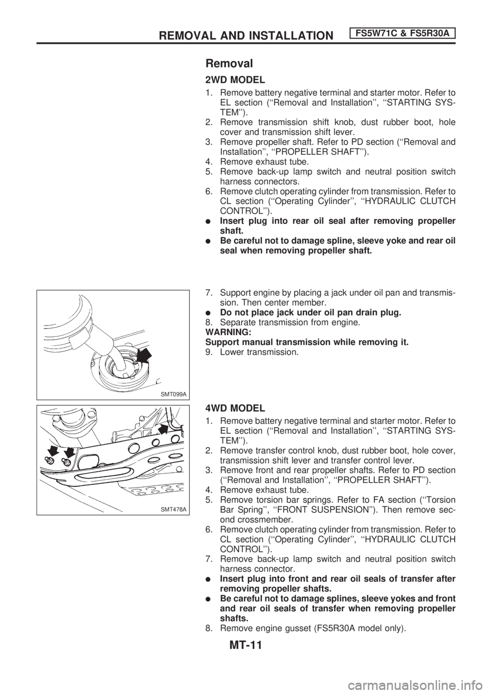
lInsert plug into rear oil seal after removing propeller
shaft.
lBe careful not to damage spline, sleeve yoke and rear oil
seal when removing propeller shaft.
7. Support engine by placing a jack under oil pan and transmis-
sion. Then center member.
lDo not place jack under oil pan drain plug.
8. Separate transmission from engine.
WARNING:
Support manual transmission while removing it.
9. Lower transmission.
4WD MODEL
1. Remove battery negative terminal and starter motor. Refer to
EL section (``Removal and Installation'', ``STARTING SYS-
TEM'').
2. Remove transfer control knob, dust rubber boot, hole cover,
transmission shift lever and transfer control lever.
3. Remove front and rear propeller shafts. Refer to PD section
(``Removal and Installation'', ``PROPELLER SHAFT'').
4. Remove exhaust tube.
5. Remove torsion bar springs. Refer to FA section (``Torsion
Bar Spring'', ``FRONT SUSPENSION''). Then remove sec-
ond crossmember.
6. Remove clutch operating cylinder from transmission. Refer to
CL section (``Operating Cylinder'', ``HYDRAULIC CLUTCH
CONTROL'').
7. Remove back-up lamp switch and neutral position switch
harness connector.
lInsert plug into front and rear oil seals of transfer after
removing propeller shafts.
lBe careful not to damage splines, sleeve yokes and front
and rear oil seals of transfer when removing propeller
shafts.
8. Remove engine gusset (FS5R30A model only).
SMT099A
SMT478A
REMOVAL AND INSTALLATIONFS5W71C & FS5R30A
MT-11
Page 1163 of 1659
RESTRAINT SYSTEM
SECTION
RS
CONTENTS
PRECAUTION............................................................ 1
Supplemental Restraint System (SRS) ``AIR
BAG'' (4WD models).............................................. 1
Supplemental Restraint System (SRS) ``AIR
BAG'' (2WD models).............................................. 1
SEAT BELTS............................................................. 2
Front Seat Belt ....................................................... 3
Rear Seat Belt ....................................................... 4
SUPPLEMENTAL RESTRAINT SYSTEM (SRS)..... 6
Precautions for SRS ``AIR BAG'' Service .............. 6
Special Service Tools ............................................ 6
Description ............................................................. 7
SRS Component Parts Location............................ 8
Maintenance Items................................................. 9
Removal and Installation - Diagnosis Sensor
Unit (4WD models) .............................................. 10
Removal and Installation - Air Bag Module and
Spiral Cable (4WD models) ................................. 11
Removal and Installation - Air Bag Module and
Spiral Cable (2WD models) ................................. 11
Removal - Air Bag Module and Spiral Cable ...... 12
Installation - Air Bag Module and Spiral Cable ... 13
Disposal of Air Bag Module ................................. 14TROUBLE DIAGNOSES - Supplemental
Restraint System (SRS) - 2WD models................ 17
How to Perform Trouble Diagnoses for Quick
and Accurate Repair ............................................ 17
Wiring Diagram - SRS - ....................................... 18
Self-diagnosis....................................................... 19
COLLISION DIAGNOSIS - 2WD models............... 21
TROUBLE DIAGNOSES - Supplemental
Restraint System (SRS) -....................................... 22
Trouble Diagnoses Introduction ........................... 22
How to Perform Trouble Diagnoses for Quick
and Accurate Repair ............................................ 24
Wiring Diagram - SRS - ....................................... 26
SRS Operation Check ......................................... 28
Trouble Diagnoses with CONSULT ..................... 29
Trouble Diagnoses without CONSULT ................ 37
Trouble Diagnoses: Air Bag Warning Lamp
Does Not Turn OFF ............................................. 40
Trouble Diagnoses: Air Bag Warning Lamp
Does Not Turn ON ............................................... 41
Trouble Diagnoses: SRS Does Not Enter
Diagnosis Mode Using Door Switch .................... 41
COLLISION DIAGNOSIS - 4WD models............... 42
When you read wiring diagrams:
lRead GI section, ``HOW TO READ WIRING DIAGRAMS''.
lSee EL section, ``POWER SUPPLY ROUTING'' for power distribution circuit.
When you perform trouble diagnoses, read GI section, ``HOW TO FOLLOW FLOW CHART
IN TROUBLE DIAGNOSES'' and ``HOW TO PERFORM EFFICIENT DIAGNOSIS FOR AN
ELECTRICAL INCIDENT''.
RS
Page 1164 of 1659
Supplemental Restraint System (SRS) ``AIR
BAG'' (4WD models)
The Supplemental Restraint System ``AIR BAG'', used along with a seat belt, helps to reduce the risk or
severity of injury to the driver in a frontal collision. The Supplemental Restraint System consists of air bag
module (located in the center of the steering wheel), diagnosis sensor unit, warning lamp, wiring harness
and spiral cable.
WARNING:
lTo avoid rendering the SRS inoperative, which could increase the risk of personal injury or death
in the event of a collision which would result in air bag inflation, all maintenance must be per-
formed by an authorized NISSAN dealer.
lImproper maintenance, including incorrect removal and installation of the SRS, can lead to per-
sonal injury caused by unintentional activation of the system.
lDo not use electrical test equipment on any circuit related to the SRS unless instructed to in this
Service Manual. SRS wiring harnesses are covered with yellow insulation either just before the
harness connectors or for the complete harness, for easy identification.
Supplemental Restraint System (SRS) ``AIR
BAG'' (2WD models)
The Supplemental Restraint System ``AIR BAG'', used along with a seat belt, helps to reduce the risk or
severity of injury to the driver in a frontal collision. The Supplemental Restraint System consists of air bag
module (located in the center of the steering wheel), diagnosis sensor unit, warning lamp, wiring harness
and spiral cable.
WARNING:
lTo avoid rendering the SRS inoperative, which could increase the risk of personal injury or death
in the event of a collision which would result in air bag inflation, all maintenance must be per-
formed by an authorized NISSAN dealer.
lImproper maintenance, including incorrect removal and installation of the SRS, can lead to per-
sonal injury caused by unintentional activation of the system.
lDo not use electrical test equipment on any circuit related to the SRS unless instructed to in this
Service Manual.
PRECAUTION
RS-1
Page 1172 of 1659
Maintenance Items
CAUTION:
Do not use a circuit tester to check SRS circuit.
1. Check ``AIR BAG'' warning lamp operation.
After turning ignition key to ``ON'' position, ``AIR BAG'' warn-
ing lamp illuminates. The ``AIR BAG'' warning lamp will turn
off after about 7 seconds if no malfunction is detected.
If any of the following air bag warning lamp conditions occur,
immediately check the air bag system. Refer to RS-28 (4WD
models), RS-19 (2WD models) for details.
lThe warning lamp does not illuminate when the ignition
switch is turned ``ON''.
lThe warning lamp does not turn off about 7 seconds after the
ignition switch is turned ``ON''.
lThe warning lamp blinks about 7 seconds after the ignition
switch is turned ``ON''.
2. Visually check SRS components.
(1) Diagnosis sensor unit
lCheck diagnosis sensor unit and bracket for dents, cracks or
deformities.
lCheck connectors for damage, and terminals for deformities.
(2) Air bag module and steering wheel
lRemove air bag module from steering wheel. Check harness
cover and connectors for damage, terminals for deformities,
and harness for binding.
lInstall driver side air bag module to steering wheel to check
fit and alignment with the wheel.
lCheck steering wheel for excessive free play.
(3) Spiral cable
lCheck spiral cable for dents, cracks, or deformities.
lCheck connectors and protective tape for damage.
lCheck steering wheel for noise, binding or heavy operation.
(4) Main harness and air bag harness
lCheck connectors for poor connections, damage, and termi-
nals for deformities.
lCheck harnesses for binding, chafing or cut.
CAUTION:
Replace previously used special bolts and ground bolt with
new ones.
SRS296
SUPPLEMENTAL RESTRAINT SYSTEM (SRS)
RS-9
Page 1177 of 1659

7. Position air bag module and tighten with new special bolts.
8. Connect air bag module connector.
9. Install all lids.
10. Conduct self-diagnosis to ensure entire SRS operates prop-
erly. (Use CONSULT or warning lamp check.)
Before performing self-diagnosis, connect both battery
cables.
11. Turn steering wheel to the left end and then to the right end
fully to make sure that spiral cable is set in the neutral posi-
tion.
If air bag warning lamp blinks or stays ON (at the user mode),
it shows the spiral cable may be snapped due to its improper
position. Perform self-diagnosis again (use CONSULT or
warning lamp). If a malfunction is detected, replace the spi-
ral cable with a new one.
Disposal of Air Bag Module
lBefore disposing of air bag modules or vehicles equipped with such a system, deploy the system. If such
a system has already been deployed due to an accident, dispose of as indicated in ``DISPOSING OF
AIR BAG MODULE'' (RS-16).
lWhen deploying the air bag module, always use the Special Service Tool; Deployment tool KV99106400.
lWhen deploying the air bag module stand at least 5 m (16 ft) away from the deployment component.
lWhen deploying the air bag module, a fairly loud noise is made, followed by smoke being released. The
smoke is not poisonous, however, be careful not to inhale smoke since it irritates throat and can cause
choking.
lAlways activate one air bag module at a time.
lDue to heat, leave air bag module unattended for more than 30 minutes after deployment.
lBe sure to wear gloves when handling a deployed air bag module.
lNever apply water to a deployed air bag module.
lWash your hands clean after finishing work.
lPlace the vehicle outdoors with an open space of at least 6 m (20 ft) on all sides when deploying the
air bag module while mounted in vehicle.
lUse a voltmeter to make sure the vehicle battery is fully charged.
lDo not dispose of the air bag module un-deployed.
CHECKING DEPLOYMENT TOOL
Connecting to battery
CAUTION:
The battery must show voltage of 9.6V or more.
Remove the battery from the vehicle and place it on dry wood
blocks approximately 5 m (16 ft) away from the vehicle.
lWait 10 to 12 minutes after the vehicle battery is discon-
nected before proceeding.
lConnect red clip of deployment tool to battery positive termi-
nal and black clip to negative terminal.
Make sure the polarity is correct. The right side lamp in the
tool, marked ``deployment tool power'', should glow with a
green light. If the right side lamp glows red, reverse the
connections to the battery.
SBF812EA
SRS005-B
SUPPLEMENTAL RESTRAINT SYSTEM (SRS)
Installation Ð Air Bag Module and Spiral
Cable (Cont'd)
RS-14
Page 1180 of 1659
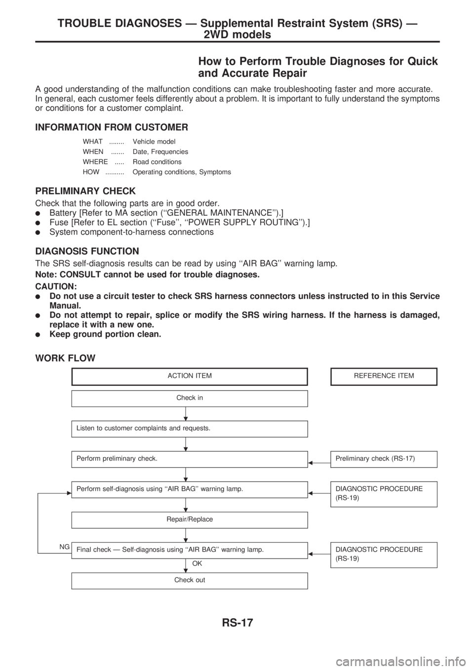
How to Perform Trouble Diagnoses for Quick
and Accurate Repair
A good understanding of the malfunction conditions can make troubleshooting faster and more accurate.
In general, each customer feels differently about a problem. It is important to fully understand the symptoms
or conditions for a customer complaint.
INFORMATION FROM CUSTOMER
WHAT ........ Vehicle model
WHEN ....... Date, Frequencies
WHERE ..... Road conditions
HOW .......... Operating conditions, Symptoms
PRELIMINARY CHECK
Check that the following parts are in good order.
lBattery [Refer to MA section (``GENERAL MAINTENANCE'').]
lFuse [Refer to EL section (``Fuse'', ``POWER SUPPLY ROUTING'').]
lSystem component-to-harness connections
DIAGNOSIS FUNCTION
The SRS self-diagnosis results can be read by using ``AIR BAG'' warning lamp.
Note: CONSULT cannot be used for trouble diagnoses.
CAUTION:
lDo not use a circuit tester to check SRS harness connectors unless instructed to in this Service
Manual.
lDo not attempt to repair, splice or modify the SRS wiring harness. If the harness is damaged,
replace it with a new one.
lKeep ground portion clean.
WORK FLOW
ACTION ITEMREFERENCE ITEM
Check in
Listen to customer complaints and requests.
Perform preliminary check.bPreliminary check (RS-17)
cPerform self-diagnosis using ``AIR BAG'' warning lamp.bDIAGNOSTIC PROCEDURE
(RS-19)
Repair/Replace
NGFinal check Ð Self-diagnosis using ``AIR BAG'' warning lamp.
OK
bDIAGNOSTIC PROCEDURE
(RS-19)
Check out
.
.
.
.
.
.
TROUBLE DIAGNOSES Ð Supplemental Restraint System (SRS) Ð
2WD models
RS-17
Page 1182 of 1659
Self-diagnosis
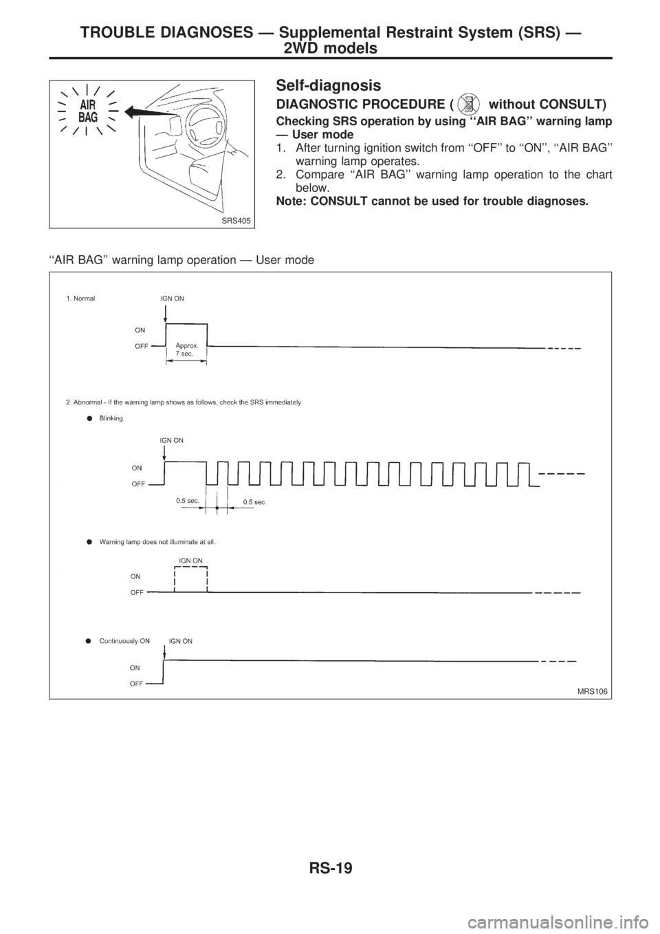
DIAGNOSTIC PROCEDURE (without CONSULT)
Checking SRS operation by using ``AIR BAG'' warning lamp
Ð User mode
1. After turning ignition switch from ``OFF'' to ``ON'', ``AIR BAG''
warning lamp operates.
2. Compare ``AIR BAG'' warning lamp operation to the chart
below.
Note: CONSULT cannot be used for trouble diagnoses.
``AIR BAG'' warning lamp operation Ð User mode
SRS405
MRS106
TROUBLE DIAGNOSES Ð Supplemental Restraint System (SRS) Ð
2WD models
RS-19
Page 1183 of 1659

REPAIR PROCEDURES
CAUTION:
Before servicing air bag, turn the ignition switch off and disconnect both battery cables and wait at
least 3 minutes.
Warning lamp operation Explanation Repair order
Warning lamp blinks.*Open or short in the air bag module cir-
cuit.1. Visually check the wiring harness and connectors.
2. Replace air bag module.
3. Replace steering wheel assembly (including diagnosis
sensor unit). Malfunctioning diagnosis sensor unit
Warning lamp does not illu-
minate at all.Meter fuse is blown.
1. Check meter fuse.
2. Visually check the wiring harnesses and connectors.
3. Check warning lamp LED.
4. Replace spiral cable.
5. Replace steering wheel assembly (including diagnosis
sensor unit).
6. Replace combination meter. Open in the warning lamp power supply
circuit
Short circuit between the warning lamp
and diagnoses sensor unit.
Malfunctioning LED
Malfunctioning combination meter
Malfunctioning diagnosis sensor unit
Warning lamp is continu-
ously ON.SRS air bag fuse is blown.1. Check air bag fuse.
2. Visually check the wiring harnesses and connectors for
combination meter, diagnosis sensor unit and spiral
cable.
3. Replace spiral cable.
4. Replace steering wheel assembly (including diagnosis
sensor unit). Open in circuit between the warning
lamp and diagnoses sensor unit.
Malfunctioning diagnosis sensor unit
*: After air bag is deployed, the warning lamp might blink due to an open circuit in the air bag module.
Follow the procedures in numerical order when repairing malfunctioning parts. Confirm whether malfunction is eliminated
using the air bag warning lamp each time repair is finished. If malfunction is still observed, proceed to the next step. When
malfunction is eliminated, further repair work is not required.
TROUBLE DIAGNOSES Ð Supplemental Restraint System (SRS) Ð
2WD models
Self-diagnosis (Cont'd)
RS-20