1998 NISSAN PICK-UP warning
[x] Cancel search: warningPage 704 of 1659
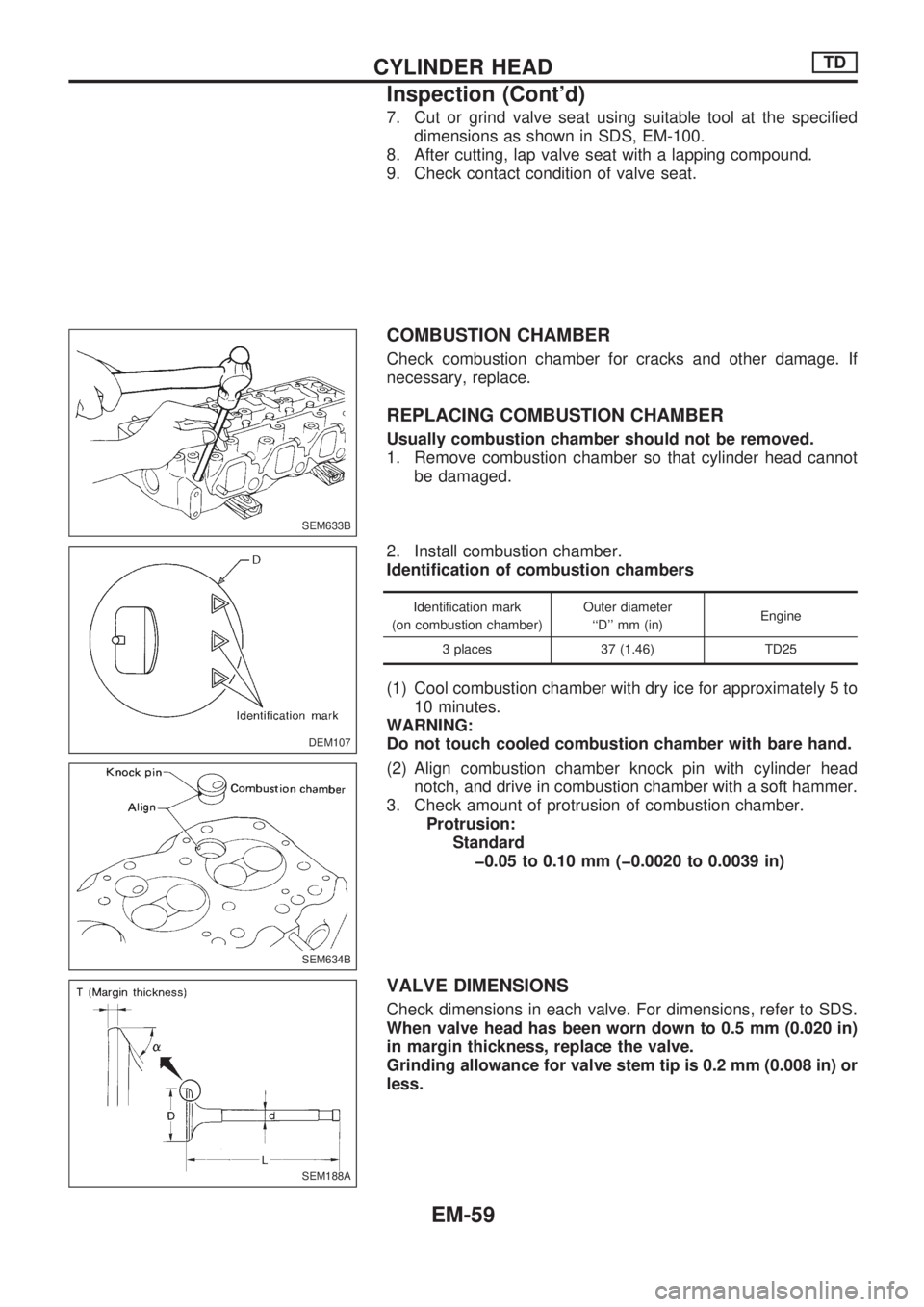
7. Cut or grind valve seat using suitable tool at the specified
dimensions as shown in SDS, EM-100.
8. After cutting, lap valve seat with a lapping compound.
9. Check contact condition of valve seat.
COMBUSTION CHAMBER
Check combustion chamber for cracks and other damage. If
necessary, replace.
REPLACING COMBUSTION CHAMBER
Usually combustion chamber should not be removed.
1. Remove combustion chamber so that cylinder head cannot
be damaged.
2. Install combustion chamber.
Identification of combustion chambers
Identification mark
(on combustion chamber)Outer diameter
``D'' mm (in)Engine
3 places 37 (1.46) TD25
(1) Cool combustion chamber with dry ice for approximately 5 to
10 minutes.
WARNING:
Do not touch cooled combustion chamber with bare hand.
(2) Align combustion chamber knock pin with cylinder head
notch, and drive in combustion chamber with a soft hammer.
3. Check amount of protrusion of combustion chamber.
Protrusion:
Standard
þ0.05 to 0.10 mm (þ0.0020 to 0.0039 in)
VALVE DIMENSIONS
Check dimensions in each valve. For dimensions, refer to SDS.
When valve head has been worn down to 0.5 mm (0.020 in)
in margin thickness, replace the valve.
Grinding allowance for valve stem tip is 0.2 mm (0.008 in) or
less.
SEM633B
DEM107
.
SEM634B
SEM188A
CYLINDER HEADTD
Inspection (Cont'd)
EM-59
Page 714 of 1659
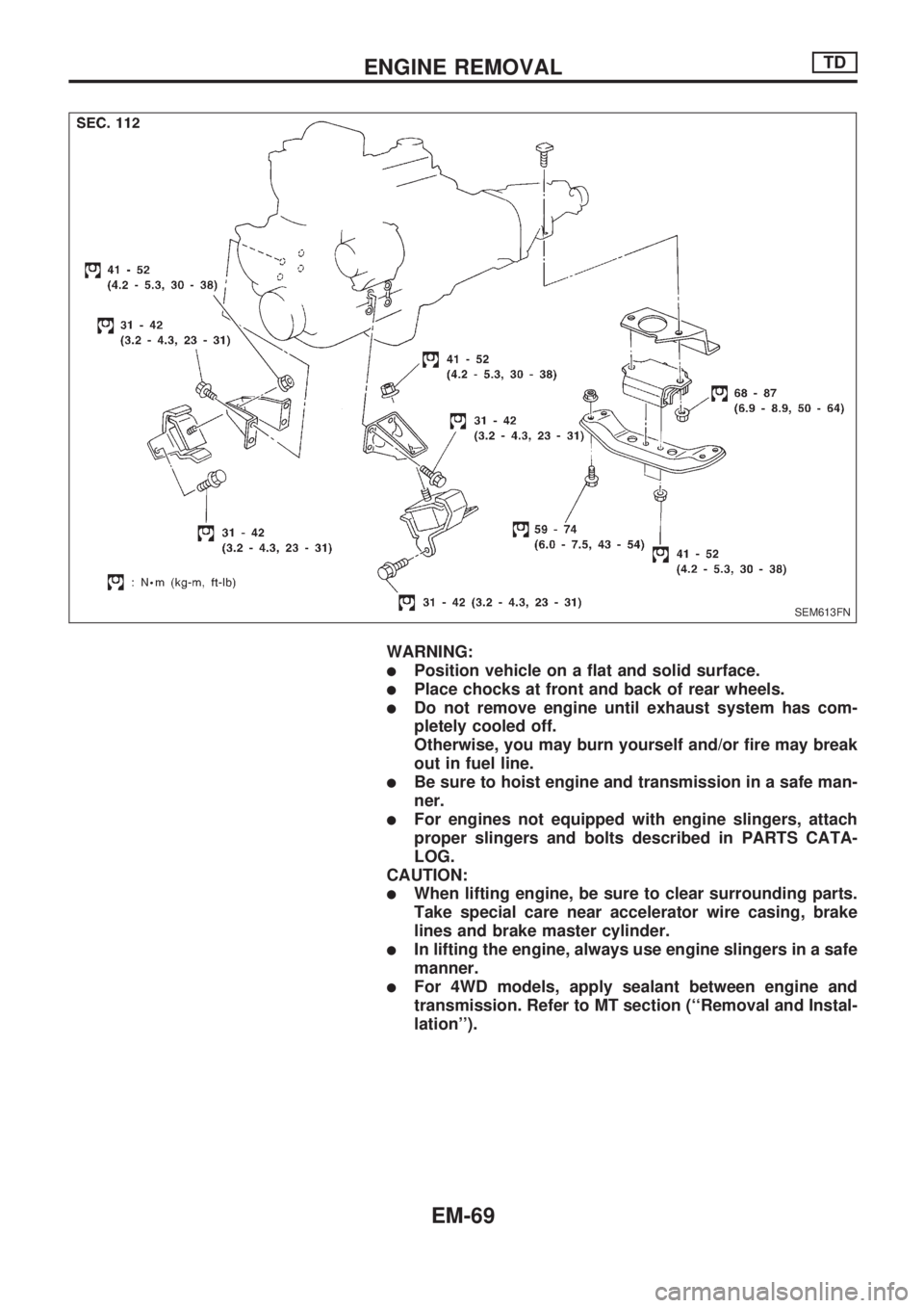
WARNING:
lPosition vehicle on a flat and solid surface.
lPlace chocks at front and back of rear wheels.
lDo not remove engine until exhaust system has com-
pletely cooled off.
Otherwise, you may burn yourself and/or fire may break
out in fuel line.
lBe sure to hoist engine and transmission in a safe man-
ner.
lFor engines not equipped with engine slingers, attach
proper slingers and bolts described in PARTS CATA-
LOG.
CAUTION:
lWhen lifting engine, be sure to clear surrounding parts.
Take special care near accelerator wire casing, brake
lines and brake master cylinder.
lIn lifting the engine, always use engine slingers in a safe
manner.
lFor 4WD models, apply sealant between engine and
transmission. Refer to MT section (``Removal and Instal-
lation'').
SEM613FN
ENGINE REMOVALTD
EM-69
Page 759 of 1659
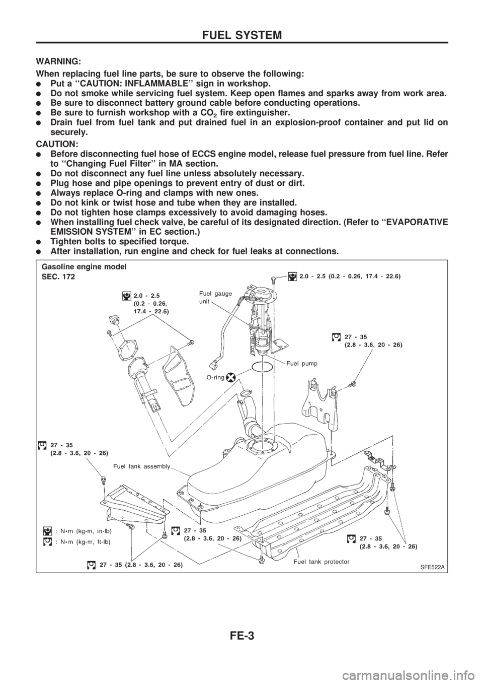
WARNING:
When replacing fuel line parts, be sure to observe the following:
lPut a ``CAUTION: INFLAMMABLE'' sign in workshop.
lDo not smoke while servicing fuel system. Keep open flames and sparks away from work area.
lBe sure to disconnect battery ground cable before conducting operations.
lBe sure to furnish workshop with a CO2fire extinguisher.
lDrain fuel from fuel tank and put drained fuel in an explosion-proof container and put lid on
securely.
CAUTION:
lBefore disconnecting fuel hose of ECCS engine model, release fuel pressure from fuel line. Refer
to ``Changing Fuel Filter'' in MA section.
lDo not disconnect any fuel line unless absolutely necessary.
lPlug hose and pipe openings to prevent entry of dust or dirt.
lAlways replace O-ring and clamps with new ones.
lDo not kink or twist hose and tube when they are installed.
lDo not tighten hose clamps excessively to avoid damaging hoses.
lWhen installing fuel check valve, be careful of its designated direction. (Refer to ``EVAPORATIVE
EMISSION SYSTEM'' in EC section.)
lTighten bolts to specified torque.
lAfter installation, run engine and check for fuel leaks at connections.
SFE522A
FUEL SYSTEM
FE-3
Page 775 of 1659
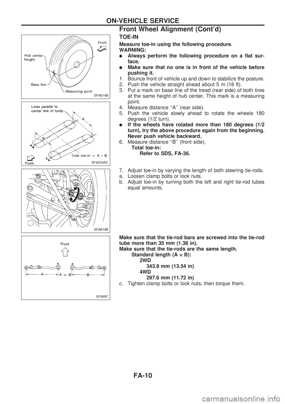
TOE-IN
Measure toe-in using the following procedure.
WARNING:
lAlways perform the following procedure on a flat sur-
face.
lMake sure that no one is in front of the vehicle before
pushing it.
1. Bounce front of vehicle up and down to stabilize the posture.
2. Push the vehicle straight ahead about 5 m (16 ft).
3. Put a mark on base line of the tread (rear side) of both tires
at the same height of hub center. This mark is a measuring
point.
4. Measure distance ``A'' (rear side).
5. Push the vehicle slowly ahead to rotate the wheels 180
degrees (1/2 turn).
lIf the wheels have rotated more than 180 degrees (1/2
turn), try the above procedure again from the beginning.
Never push vehicle backward.
6. Measure distance ``B'' (front side).
Total toe-in:
Refer to SDS, FA-36.
7. Adjust toe-in by varying the length of both steering tie-rods.
a. Loosen clamp bolts or lock nuts.
b. Adjust toe-in by turning both the left and right tie-rod tubes
equal amounts.
Make sure that the tie-rod bars are screwed into the tie-rod
tube more than 35 mm (1.38 in).
Make sure that the tie-rods are the same length.
Standard length (A = B):
2WD
343.9 mm (13.54 in)
4WD
297.6 mm (11.72 in)
c. Tighten clamp bolts or lock nuts, then torque them.
SFA614B
SFA234AC
SFA819B
SFA897
ON-VEHICLE SERVICE
Front Wheel Alignment (Cont'd)
FA-10
Page 805 of 1659
Observe the following precautions to ensure safe and
proper servicing. These precautions are not described in
each individual section.
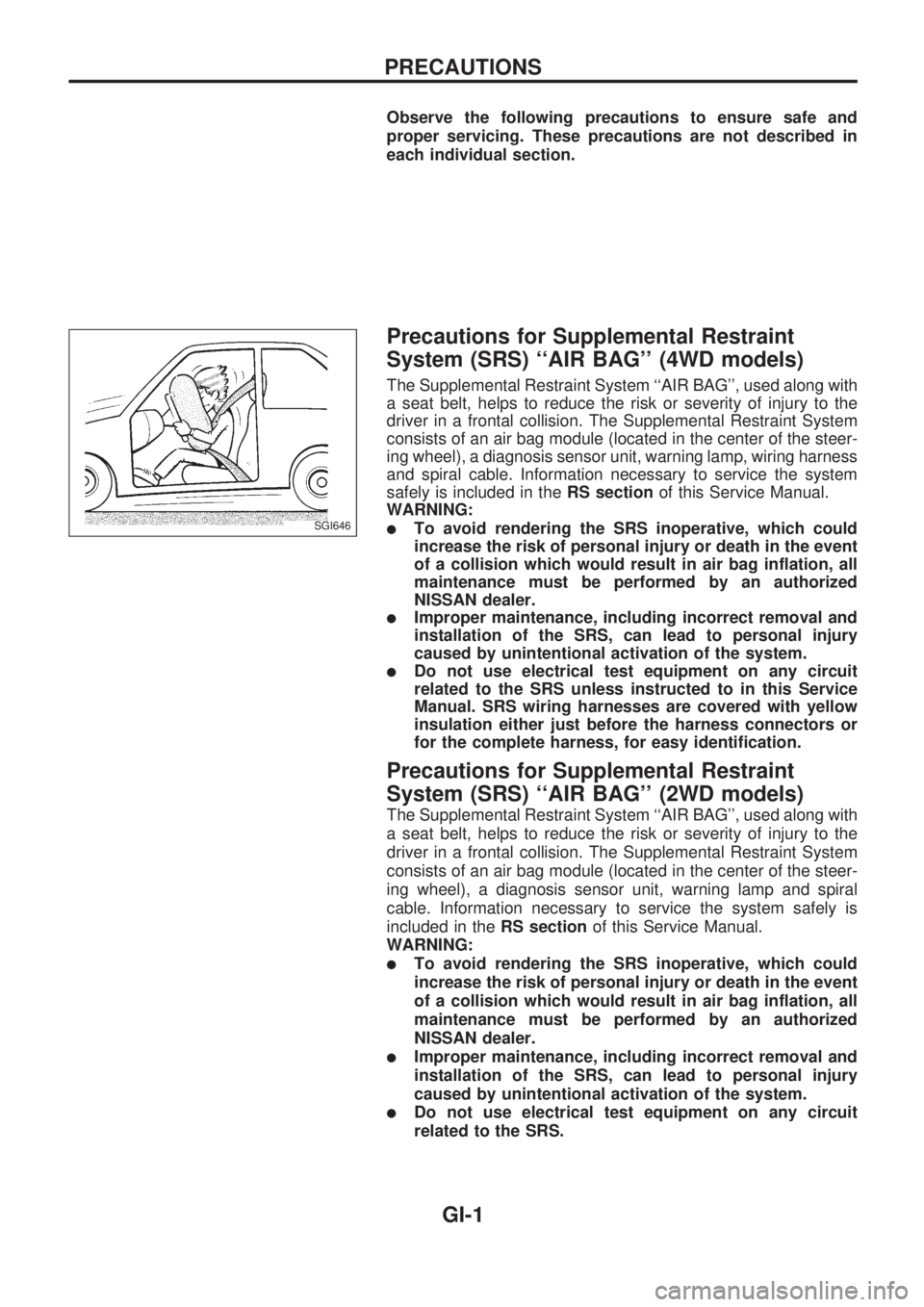
Precautions for Supplemental Restraint
System (SRS) ``AIR BAG'' (4WD models)
The Supplemental Restraint System ``AIR BAG'', used along with
a seat belt, helps to reduce the risk or severity of injury to the
driver in a frontal collision. The Supplemental Restraint System
consists of an air bag module (located in the center of the steer-
ing wheel), a diagnosis sensor unit, warning lamp, wiring harness
and spiral cable. Information necessary to service the system
safely is included in theRS sectionof this Service Manual.
WARNING:
lTo avoid rendering the SRS inoperative, which could
increase the risk of personal injury or death in the event
of a collision which would result in air bag inflation, all
maintenance must be performed by an authorized
NISSAN dealer.
lImproper maintenance, including incorrect removal and
installation of the SRS, can lead to personal injury
caused by unintentional activation of the system.
lDo not use electrical test equipment on any circuit
related to the SRS unless instructed to in this Service
Manual. SRS wiring harnesses are covered with yellow
insulation either just before the harness connectors or
for the complete harness, for easy identification.
Precautions for Supplemental Restraint
System (SRS) ``AIR BAG'' (2WD models)
The Supplemental Restraint System ``AIR BAG'', used along with
a seat belt, helps to reduce the risk or severity of injury to the
driver in a frontal collision. The Supplemental Restraint System
consists of an air bag module (located in the center of the steer-
ing wheel), a diagnosis sensor unit, warning lamp and spiral
cable. Information necessary to service the system safely is
included in theRS sectionof this Service Manual.
WARNING:
lTo avoid rendering the SRS inoperative, which could
increase the risk of personal injury or death in the event
of a collision which would result in air bag inflation, all
maintenance must be performed by an authorized
NISSAN dealer.
lImproper maintenance, including incorrect removal and
installation of the SRS, can lead to personal injury
caused by unintentional activation of the system.
lDo not use electrical test equipment on any circuit
related to the SRS.
SGI646
PRECAUTIONS
GI-1
Page 808 of 1659
lAfter disconnecting vacuum or air hoses, attach a tag to
indicate the proper connection.
lUse only the fluids and lubricants specified in this manual.
lUse approved bonding agent, sealants or their equivalents
when required.
lUse tools and recommended special tools where specified
for safe and efficient service repairs.
lWhen repairing the fuel, oil, water, vacuum or exhaust
systems, check all affected lines for leaks.
lDispose of drained oil or the solvent used for cleaning parts
in an appropriate manner.
WARNING:
To prevent ECM from storing the diagnostic trouble codes,
do not carelessly disconnect the harness connectors which
are related to the ECCS system and TCM (Transmission
Control Module) system. The connectors should be discon-
nected only when working according to the WORK FLOW of
TROUBLE DIAGNOSES in EC section.
Precautions for Multiport Fuel Injection
System or ECCS Engine
lBefore connecting or disconnecting any harness connector
for the multiport fuel injection system or ECM (Engine Con-
trol Module):
Turn ignition switch to ``OFF'' position.
Disconnect negative battery terminal.
Otherwise, there may be damage to ECM.
lBefore disconnecting pressurized fuel line from fuel pump to
injectors, be sure to release fuel pressure.
lBe careful not to jar components such as ECM and mass air
flow sensor.
Precautions for Three Way Catalyst
(If so equipped)
If a large amount of unburned fuel flows into the catalyst, the
catalyst temperature will be excessively high. To prevent this,
follow the instructions below:
lUse unleaded gasoline only. Leaded gasoline will seriously
damage the three way catalyst.
lWhen checking for ignition spark or measuring engine
compression, make tests quickly and only when necessary.
lDo not run engine when the fuel tank level is low, otherwise
the engine may misfire causing damage to the catalyst.
Do not place the vehicle on flammable material. Keep flammable
material off the exhaust pipe and the three way catalyst.
Precautions for Engine Oils
Prolonged and repeated contact with used engine oil may cause
skin cancer. Try to avoid direct skin contact with used oil.
SGI787
PRECAUTIONS
General Precautions (Cont'd)
GI-4
Page 812 of 1659
lThe followingSYMBOLS AND ABBREVIATIONSare used:
,: Tightening torque
: Should be lubricated with grease.
Unless otherwise indicated, use
recommended multi-purpose
grease.
: Should be lubricated with oil.
: Sealing point
: Checking point
: Always replace after every disas-
sembly.
VP: Apply petroleum jelly.
: Apply ATF.
.: Select with proper thickness.
>: Adjustment is required.
SDS : Service Data and Specifications
LH, RH : Left-Hand, Right-Hand
FR, RR : Front, Rear
M/T : Manual Transaxle/Transmission
A/T : Automatic Transaxle/Transmission
,
4WD : 4-Wheel Drive
2WD : 2-Wheel Drive
A/C : Air Conditioner
P/S : Power Steering
SST : Special Service Tools
SAE : Society of Automotive Engineers,
Inc.
ATF : Automatic Transmission Fluid
D
1: Drive range 1st gear
D
2: Drive range 2nd gear
D
3: Drive range 3rd gear
D
4: Drive range 4th gear
OD : Overdrive
2
2: 2nd range 2nd gear
2
1: 2nd range 1st gear
1
2: 1st range 2nd gear
1
1: 1st range 1st gear
lTheUNITSgiven in this manual are primarily expressed as the SI UNIT (International System of Unit),
and alternatively expressed in the metric system and in the yard/pound system.
``Example''
Tightening torque:
59 - 78 N´m (6.0 - 8.0 kg-m, 43 - 58 ft-lb)
lTROUBLE DIAGNOSESare included in sections dealing with complicated components.
lSERVICE DATA AND SPECIFICATIONSare contained at the end of each section for quick reference
of data.
lThe captionsWARNINGandCAUTIONwarn you of steps that must be followed to prevent personal
injury and/or damage to some part of the vehicle.
WARNINGindicates the possibility of personal injury if instructions are not followed.
CAUTIONindicates the possibility of component damage if instructions are not followed.
BOLD TYPED STATEMENTSexceptWARNINGandCAUTIONgive you helpful information.
HOW TO USE THIS MANUAL
GI-8
Page 838 of 1659
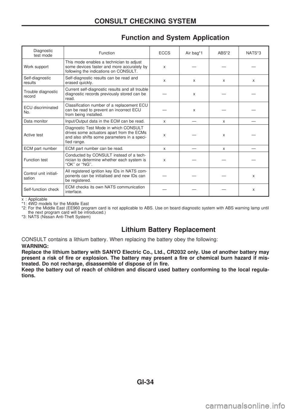
Function and System Application
Diagnostic
test modeFunction ECCS Air bag*1 ABS*2 NATS*3
Work supportThis mode enables a technician to adjust
some devices faster and more accurately by
following the indications on CONSULT.x ÐÐÐ
Self-diagnostic
resultsSelf-diagnostic results can be read and
erased quickly.xxxx
Trouble diagnostic
recordCurrent self-diagnostic results and all trouble
diagnostic records previously stored can be
read.ÐxÐÐ
ECU discriminated
No.Classification number of a replacement ECU
can be read to prevent an incorrect ECU
from being installed.ÐxÐÐ
Data monitor Input/Output data in the ECM can be read.xÐxÐ
Active testDiagnostic Test Mode in which CONSULT
drives some actuators apart from the ECMs
and also shifts some parameters in a speci-
fied range.xÐxÐ
ECM part number ECM part number can be read.xÐxÐ
Function testConducted by CONSULT instead of a tech-
nician to determine whether each system is
``OK'' or ``NG''.x ÐÐÐ
Control unit initiali-
sationAll registered ignition key IDs in NATS com-
ponents can be initialised and new IDs can
be registered.ÐÐÐ x
Self-function checkECM checks its own NATS communication
interface.ÐÐÐ x
x : Applicable
*1: 4WD models for the Middle East
*2: For the Middle East (EE960 program card is not applicable to ABS. Use on board diagnostic system with ABS warning lamp until
the next program card will be introduced.)
*3: NATS (Nissan Anti-Theft System)
Lithium Battery Replacement
CONSULT contains a lithium battery. When replacing the battery obey the following:
WARNING:
Replace the lithium battery with SANYO Electric Co., Ltd., CR2032 only. Use of another battery may
present a risk of fire or explosion. The battery may present a fire or chemical burn hazard if mis-
treated. Do not recharge, disassemble of dispose of in fire.
Keep the battery out of reach of children and discard used battery conforming to the local regula-
tions.
CONSULT CHECKING SYSTEM
GI-34