Page 469 of 1659
HEL343A
TURN SIGNAL AND HAZARD WARNING LAMPS
Wiring Diagram Ð TURN Ð/4WD Models for
Europe (Cont'd)
EL-79
Page 470 of 1659

Trouble Diagnoses
Symptom Possible cause Repair order
Turn signal and hazard warning
lamps do not operate.1. Hazard switch
2. Combination flasher unit
3. Open in combination flasher unit
circuit1. Check hazard switch.
2. Refer to combination flasher unit check.
3. Check wiring to combination flasher unit for open cir-
cuit.
Turn signal lamps do not operate
but hazard warning lamps operate.1. 7.5A fuse
2. Hazard switch
3. Turn signal switch
4. Open in turn signal switch circuit1. Check 7.5A fuse (No.
, located in fuse block).
Turn ignition switch ON and verify battery positive
voltage is present at terminal
V2of hazard switch.
2. Check hazard switch.
3. Check turn signal switch.
4. Check G wire between combination flasher unit and
turn signal switch for open circuit.
Hazard warning lamps do not oper-
ate but turn signal lamps operate.1. 10A fuse
2. Hazard switch
3. Open in hazard switch circuit1. Check 10A fuse (No.
, located in fuse block).
Verify battery positive voltage is present at terminal
V3of hazard switch.
2. Check hazard switch.
3. Check G wire between combination flasher unit and
hazard switch for open circuit.
Front or side turn signal lamp LH
or RH does not operate.1. Bulb
2. Grounds
E6andE39
1. Check bulb.
2. Check grounds
E6andE39.
Rear turn signal lamp LH or RH
does not operate.1. Bulb
2. Grounds
M1andM54
1. Check bulb.
2. Check grounds
M1andM54.
LH and RH turn indicators do not
operate.1. Ground 1. Check grounds
M1andM54.
LH or RH turn indicator does not
operate.1. Bulb 1. Check bulb in combination meter.
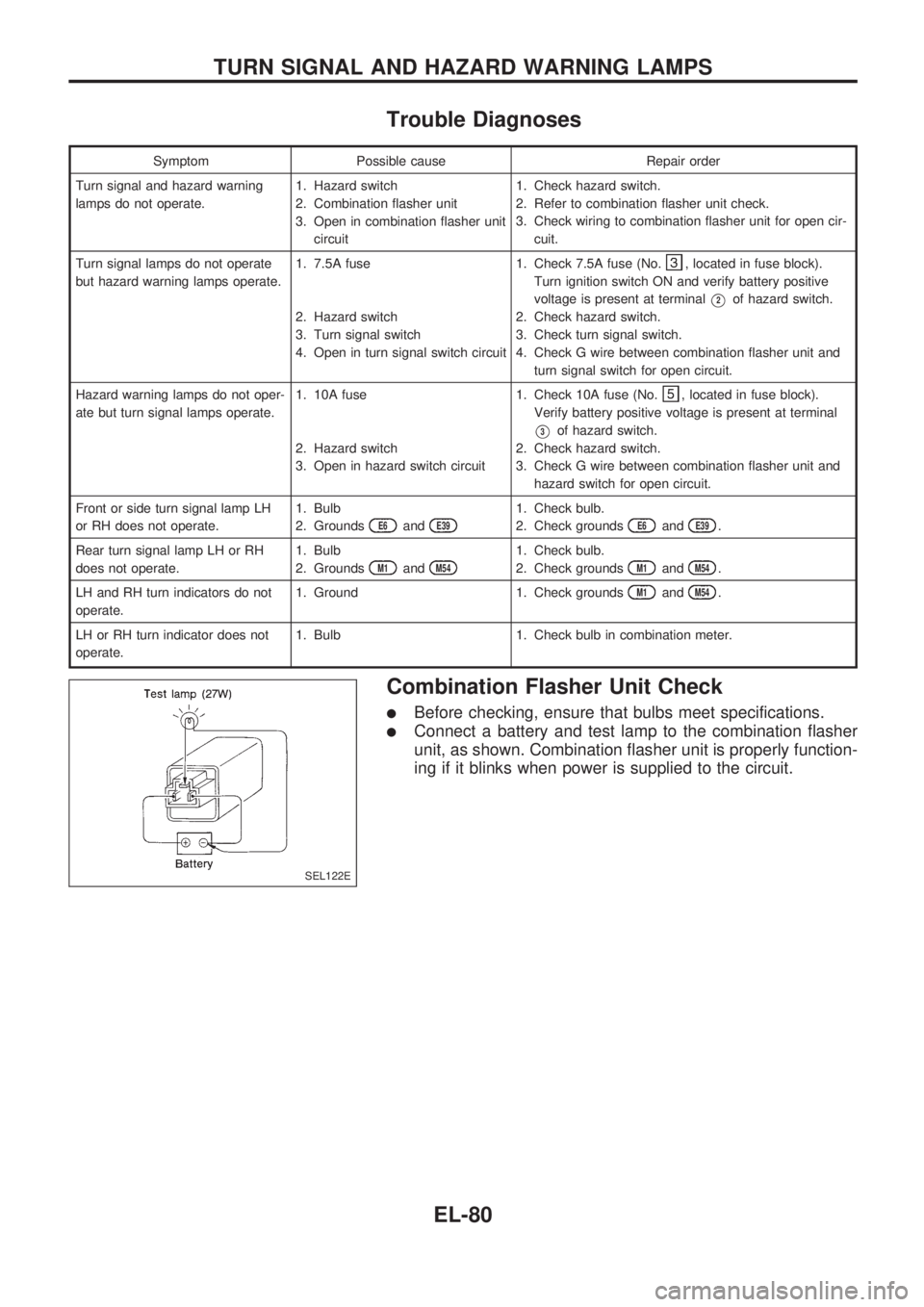
Combination Flasher Unit Check
lBefore checking, ensure that bulbs meet specifications.
lConnect a battery and test lamp to the combination flasher
unit, as shown. Combination flasher unit is properly function-
ing if it blinks when power is supplied to the circuit.
SEL122E
TURN SIGNAL AND HAZARD WARNING LAMPS
EL-80
Page 488 of 1659

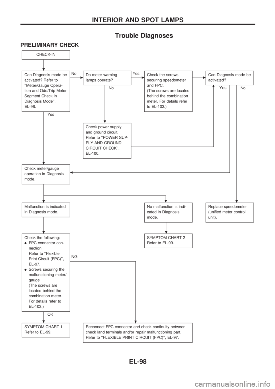
Trouble Diagnoses
PRELIMINARY CHECK
CHECK-IN
Can Diagnosis mode be
activated? Refer to
``Meter/Gauge Opera-
tion and Odo/Trip Meter
Segment Check in
Diagnosis Mode'',
EL-96.
Yes
cNo
Do meter warning
lamps operate?
No
cYes
Check the screws
securing speedometer
and FPC.
(The screws are located
behind the combination
meter. For details refer
to EL-103.)cCan Diagnosis mode be
activated?
Nom
Check power supply
and ground circuit.
Refer to ``POWER SUP-
PLY AND GROUND
CIRCUIT CHECK'',
EL-100.
Check meter/gauge
operation in Diagnosis
mode.b
Yes
.
Malfunction is indicated
in Diagnosis mode.No malfunction is indi-
cated in Diagnosis
mode.Replace speedometer
(unified meter control
unit).
Check the following:
lFPC connector con-
nection
Refer to ``Flexible
Print Circuit (FPC)'',
EL-97.
lScrews securing the
malfunctioning meter/
gauge
(The screws are
located behind the
combination meter.
For details refer to
EL-103.)
OK
.
NG
SYMPTOM CHART 2
Refer to EL-99.
SYMPTOM CHART 1
Refer to EL-99.Reconnect FPC connector and check continuity between
check land terminals and/or repair malfunctioning part.
Refer to ``FLEXIBLE PRINT CIRCUIT (FPC)'', EL-97.
.
.
.
..
..
.
INTERIOR AND SPOT LAMPS
EL-98
Page 495 of 1659
Schematic
HEL359A
WARNING LAMPS
EL-105
Page 496 of 1659
Wiring Diagram Ð WARN Ð/LHD Models
HEL360A
WARNING LAMPS
EL-106
Page 497 of 1659
HEL361A
WARNING LAMPS
Wiring Diagram Ð WARN Ð/LHD Models
(Cont'd)
EL-107
Page 498 of 1659
HEL362A
WARNING LAMPS
Wiring Diagram Ð WARN Ð/LHD Models
(Cont'd)
EL-108
Page 499 of 1659
HEL363A
WARNING LAMPS
Wiring Diagram Ð WARN Ð/LHD Models
(Cont'd)
EL-109