1998 NISSAN PICK-UP warning
[x] Cancel search: warningPage 74 of 1659
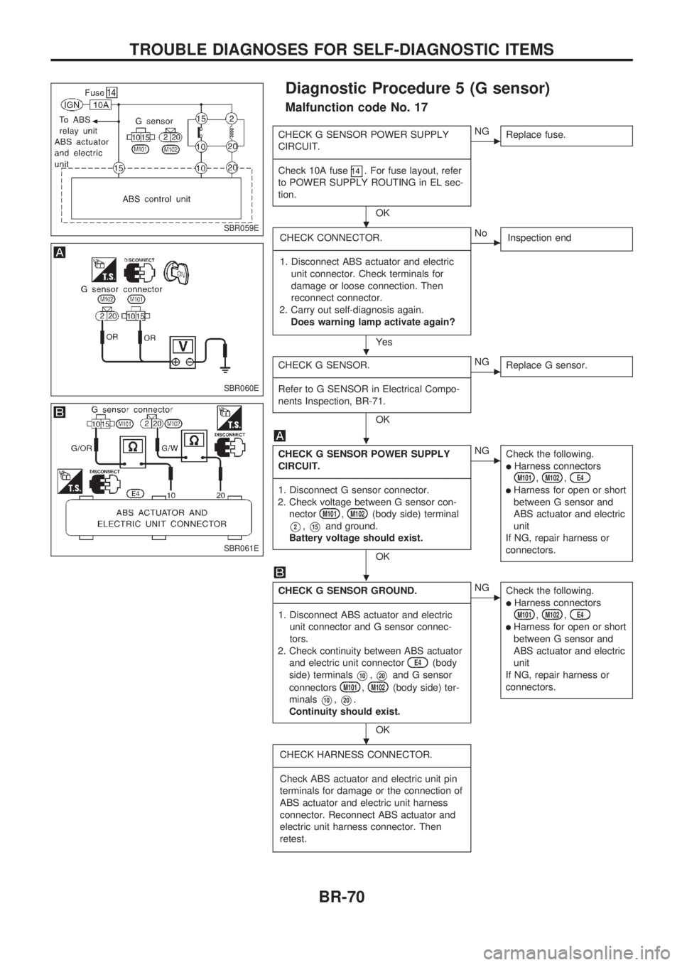
Diagnostic Procedure 5 (G sensor)
Malfunction code No. 17
CHECK G SENSOR POWER SUPPLY
CIRCUIT.
-------------------------------------------------------------------------------------------------------------------------------------------------------------------------------------------------------------------------------------------------------------------------------------------------------------
Check 10A fuse
14. For fuse layout, refer
to POWER SUPPLY ROUTING in EL sec-
tion.
OK
cNG
Replace fuse.
CHECK CONNECTOR.
-------------------------------------------------------------------------------------------------------------------------------------------------------------------------------------------------------------------------------------------------------------------------------------------------------------
1. Disconnect ABS actuator and electric
unit connector. Check terminals for
damage or loose connection. Then
reconnect connector.
2. Carry out self-diagnosis again.
Does warning lamp activate again?
Yes
cNo
Inspection end
CHECK G SENSOR.
-------------------------------------------------------------------------------------------------------------------------------------------------------------------------------------------------------------------------------------------------------------------------------------------------------------
Refer to G SENSOR in Electrical Compo-
nents Inspection, BR-71.
OK
cNG
Replace G sensor.
CHECK G SENSOR POWER SUPPLY
CIRCUIT.
-------------------------------------------------------------------------------------------------------------------------------------------------------------------------------------------------------------------------------------------------------------------------------------------------------------
1. Disconnect G sensor connector.
2. Check voltage between G sensor con-
nector
M101,M102(body side) terminal
V2,V15and ground.
Battery voltage should exist.
OK
cNG
Check the following.
lHarness connectorsM101,M102,E4
lHarness for open or short
between G sensor and
ABS actuator and electric
unit
If NG, repair harness or
connectors.
CHECK G SENSOR GROUND.
-------------------------------------------------------------------------------------------------------------------------------------------------------------------------------------------------------------------------------------------------------------------------------------------------------------
1. Disconnect ABS actuator and electric
unit connector and G sensor connec-
tors.
2. Check continuity between ABS actuator
and electric unit connector
E4(body
side) terminals
V10,V20and G sensor
connectors
M101,M102(body side) ter-
minals
V10,V20.
Continuity should exist.
OK
cNG
Check the following.
lHarness connectorsM101,M102,E4
lHarness for open or short
between G sensor and
ABS actuator and electric
unit
If NG, repair harness or
connectors.
CHECK HARNESS CONNECTOR.
-------------------------------------------------------------------------------------------------------------------------------------------------------------------------------------------------------------------------------------------------------------------------------------------------------------
Check ABS actuator and electric unit pin
terminals for damage or the connection of
ABS actuator and electric unit harness
connector. Reconnect ABS actuator and
electric unit harness connector. Then
retest.
SBR059E
SBR060E
SBR061E
.
.
.
.
.
TROUBLE DIAGNOSES FOR SELF-DIAGNOSTIC ITEMS
BR-70
Page 75 of 1659
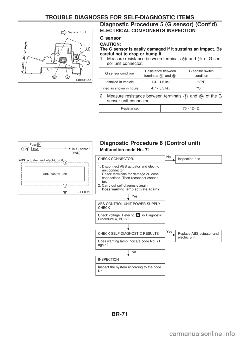
ELECTRICAL COMPONENTS INSPECTION
G sensor
CAUTION:
The G sensor is easily damaged if it sustains an impact. Be
careful not to drop or bump it.
1. Measure resistance between terminals
V10andV15of G sen-
sor unit connector.
G sensor conditionResistance between
terminalsV10andV15
G sensor switch
condition
Installed in vehicle 1.4 - 1.6 kW``ON''
Tilted as shown in figure 4.7 - 5.5 kW``OFF''
2. Measure resistance between terminalsV2andV20of the G
sensor unit connector.
Resistance: 70 - 124W
Diagnostic Procedure 6 (Control unit)
Malfunction code No. 71
CHECK CONNECTOR.
-------------------------------------------------------------------------------------------------------------------------------------------------------------------------------------------------------------------------------------------------------------------------------------------------------------
1. Disconnect ABS actuator and electric
unit connector.
Check terminals for damage or loose
connections. Then reconnect connec-
tor.
2. Carry out self-diagnosis again.
Does warning lamp activate again?
Yes
cNo
Inspection end
ABS CONTROL UNIT POWER SUPPLY
CHECK
-------------------------------------------------------------------------------------------------------------------------------------------------------------------------------------------------------------------------------------------------------------------------------------------------------------
Check voltage. Refer to
in Diagnostic
Procedure 4, BR-69.
CHECK SELF-DIAGNOSTIC RESULTS
-------------------------------------------------------------------------------------------------------------------------------------------------------------------------------------------------------------------------------------------------------------------------------------------------------------
Does warning lamp indicate code No. 71
again?
No
cYes
Replace ABS actuator and
electric unit.
INSPECTION
-------------------------------------------------------------------------------------------------------------------------------------------------------------------------------------------------------------------------------------------------------------------------------------------------------------
Inspect the system according to the code
No.
SBR844DD
SBR062E
.
.
.
TROUBLE DIAGNOSES FOR SELF-DIAGNOSTIC ITEMS
Diagnostic Procedure 5 (G sensor) (Cont'd)
BR-71
Page 77 of 1659
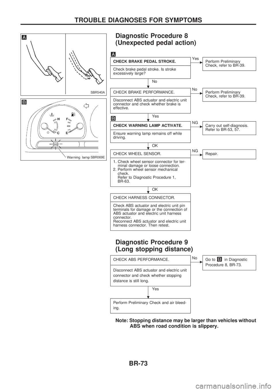
Diagnostic Procedure 8
(Unexpected pedal action)
CHECK BRAKE PEDAL STROKE.
-------------------------------------------------------------------------------------------------------------------------------------------------------------------------------------------------------------------------------------------------------------------------------------------------------------
Check brake pedal stroke. Is stroke
excessively large?
No
cYes
Perform Preliminary
Check, refer to BR-39.
CHECK BRAKE PERFORMANCE.
-------------------------------------------------------------------------------------------------------------------------------------------------------------------------------------------------------------------------------------------------------------------------------------------------------------
Disconnect ABS actuator and electric unit
connector and check whether brake is
effective.
Yes
cNo
Perform Preliminary
Check, refer to BR-39.
CHECK WARNING LAMP ACTIVATE.
-------------------------------------------------------------------------------------------------------------------------------------------------------------------------------------------------------------------------------------------------------------------------------------------------------------
Ensure warning lamp remains off while
driving.
OK
cNG
Carry out self-diagnosis.
Refer to BR-53, 57.
CHECK WHEEL SENSOR.
-------------------------------------------------------------------------------------------------------------------------------------------------------------------------------------------------------------------------------------------------------------------------------------------------------------
1. Check wheel sensor connector for ter-
minal damage or loose connection.
2. Perform wheel sensor mechanical
check.
Refer to Diagnostic Procedure 1,
BR-63.
OK
cNG
Repair.
CHECK HARNESS CONNECTOR.
-------------------------------------------------------------------------------------------------------------------------------------------------------------------------------------------------------------------------------------------------------------------------------------------------------------
Check ABS actuator and electric unit pin
terminals for damage or the connection of
ABS actuator and electric unit harness
connector.
Reconnect ABS actuator and electric unit
harness connector. Then retest.
Diagnostic Procedure 9
(Long stopping distance)
CHECK ABS PERFORMANCE.
-------------------------------------------------------------------------------------------------------------------------------------------------------------------------------------------------------------------------------------------------------------------------------------------------------------
Disconnect ABS actuator and electric unit
connector and check whether stopping
distance is still long.
Yes
cNo
Go toin Diagnostic
Procedure 8, BR-73.
Perform Preliminary Check and air bleed-
ing.
Note: Stopping distance may be larger than vehicles without
ABS when road condition is slippery.
SBR540A
SBR069E
.
.
.
.
.
TROUBLE DIAGNOSES FOR SYMPTOMS
BR-73
Page 78 of 1659
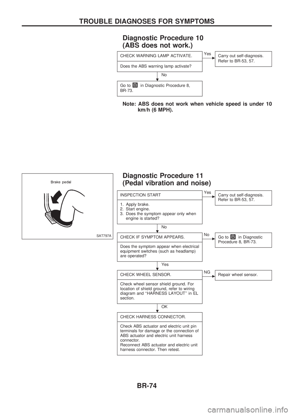
Diagnostic Procedure 10
(ABS does not work.)
CHECK WARNING LAMP ACTIVATE.
-------------------------------------------------------------------------------------------------------------------------------------------------------------------------------------------------------------------------------------------------------------------------------------------------------------
Does the ABS warning lamp activate?
No
cYes
Carry out self-diagnosis.
Refer to BR-53, 57.
Go toin Diagnostic Procedure 8,
BR-73.
Note: ABS does not work when vehicle speed is under 10
km/h (6 MPH).
Diagnostic Procedure 11
(Pedal vibration and noise)
INSPECTION START
-------------------------------------------------------------------------------------------------------------------------------------------------------------------------------------------------------------------------------------------------------------------------------------------------------------
1. Apply brake.
2. Start engine.
3. Does the symptom appear only when
engine is started?
No
cYes
Carry out self-diagnosis.
Refer to BR-53, 57.
CHECK IF SYMPTOM APPEARS.
-------------------------------------------------------------------------------------------------------------------------------------------------------------------------------------------------------------------------------------------------------------------------------------------------------------
Does the symptom appear when electrical
equipment switches (such as headlamp)
are operated?
Yes
cNo
Go toin Diagnostic
Procedure 8, BR-73.
CHECK WHEEL SENSOR.
-------------------------------------------------------------------------------------------------------------------------------------------------------------------------------------------------------------------------------------------------------------------------------------------------------------
Check wheel sensor shield ground. For
location of shield ground, refer to wiring
diagram and ``HARNESS LAYOUT'' in EL
section.
OK
cNG
Repair wheel sensor.
CHECK HARNESS CONNECTOR.
-------------------------------------------------------------------------------------------------------------------------------------------------------------------------------------------------------------------------------------------------------------------------------------------------------------
Check ABS actuator and electric unit pin
terminals for damage or the connection of
ABS actuator and electric unit harness
connector.
Reconnect ABS actuator and electric unit
harness connector. Then retest.
SAT797A
.
.
.
.
TROUBLE DIAGNOSES FOR SYMPTOMS
BR-74
Page 79 of 1659
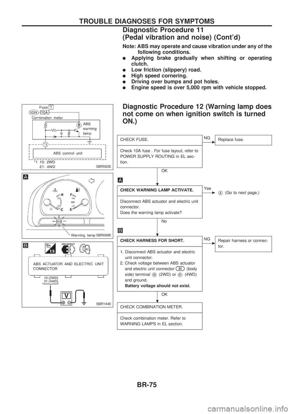
Note: ABS may operate and cause vibration under any of the
following conditions.
lApplying brake gradually when shifting or operating
clutch.
lLow friction (slippery) road.
lHigh speed cornering.
lDriving over bumps and pot holes.
lEngine speed is over 5,000 rpm with vehicle stopped.
Diagnostic Procedure 12 (Warning lamp does
not come on when ignition switch is turned
ON.)
CHECK FUSE.
-------------------------------------------------------------------------------------------------------------------------------------------------------------------------------------------------------------------------------------------------------------------------------------------------------------
Check 10A fuse . For fuse layout, refer to
POWER SUPPLY ROUTING in EL sec-
tion.
OK
cNG
Replace fuse.
CHECK WARNING LAMP ACTIVATE.
-------------------------------------------------------------------------------------------------------------------------------------------------------------------------------------------------------------------------------------------------------------------------------------------------------------
Disconnect ABS actuator and electric unit
connector.
Does the warning lamp activate?
No
cYes
VA(Go to next page.)
CHECK HARNESS FOR SHORT.
-------------------------------------------------------------------------------------------------------------------------------------------------------------------------------------------------------------------------------------------------------------------------------------------------------------
1. Disconnect ABS actuator and electric
unit connector.
2. Check voltage between ABS actuator
and electric unit connector
E4(body
side) terminal
V10(2WD) orV21(4WD)
and ground.
Battery voltage should not exist.
OK
cNG
Repair harness or connec-
tor.
CHECK COMBINATION METER.
-------------------------------------------------------------------------------------------------------------------------------------------------------------------------------------------------------------------------------------------------------------------------------------------------------------
Check combination meter. Refer to
WARNING LAMPS in EL section.
SBR063E
SBR069E
SBR144E
.
.
.
TROUBLE DIAGNOSES FOR SYMPTOMS
Diagnostic Procedure 11
(Pedal vibration and noise) (Cont'd)
BR-75
Page 80 of 1659
VA
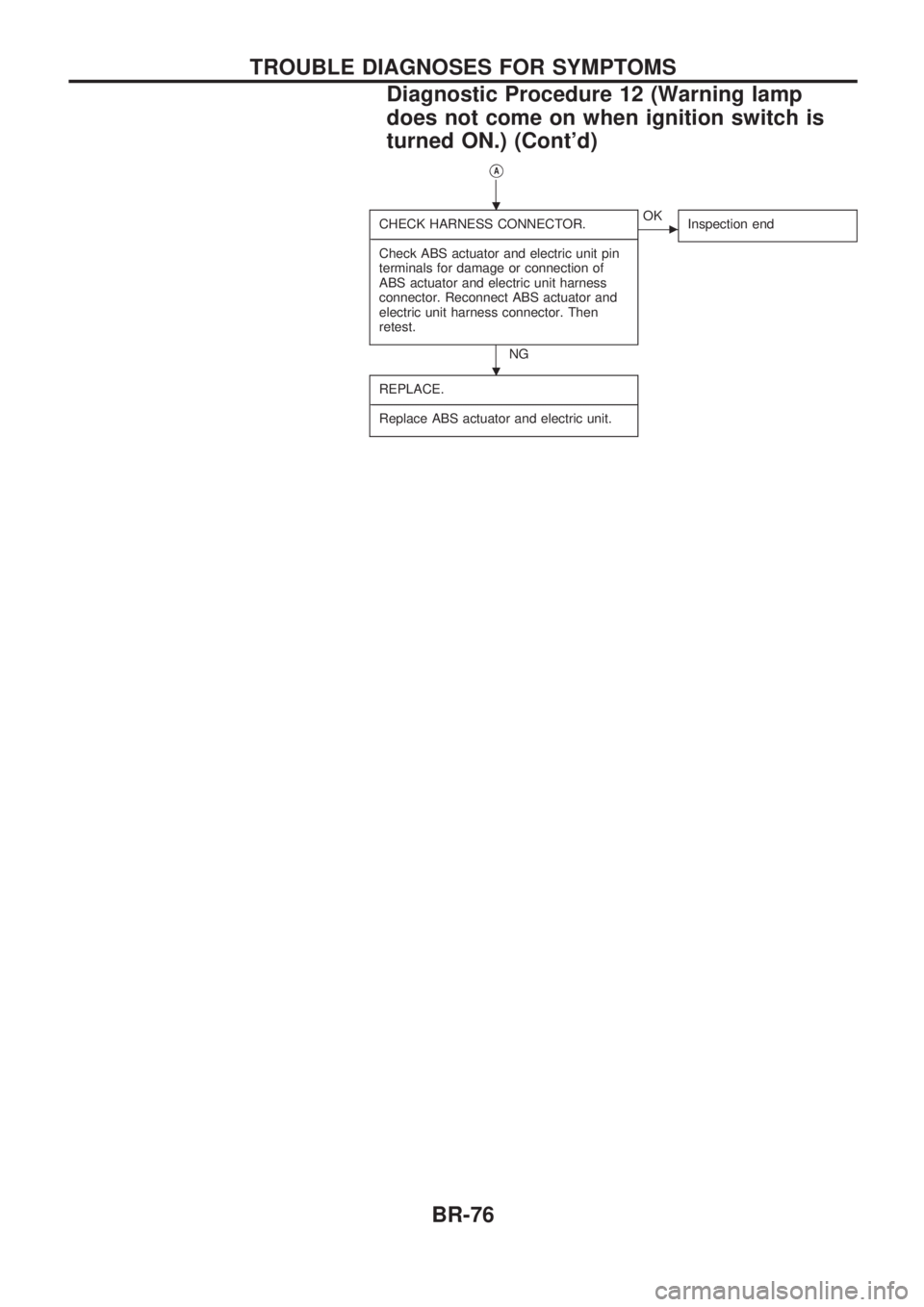
CHECK HARNESS CONNECTOR.
-------------------------------------------------------------------------------------------------------------------------------------------------------------------------------------------------------------------------------------------------------------------------------------------------------------
Check ABS actuator and electric unit pin
terminals for damage or connection of
ABS actuator and electric unit harness
connector. Reconnect ABS actuator and
electric unit harness connector. Then
retest.
NG
cOK
Inspection end
REPLACE.
-------------------------------------------------------------------------------------------------------------------------------------------------------------------------------------------------------------------------------------------------------------------------------------------------------------
Replace ABS actuator and electric unit.
.
.
TROUBLE DIAGNOSES FOR SYMPTOMS
Diagnostic Procedure 12 (Warning lamp
does not come on when ignition switch is
turned ON.) (Cont'd)
BR-76
Page 81 of 1659
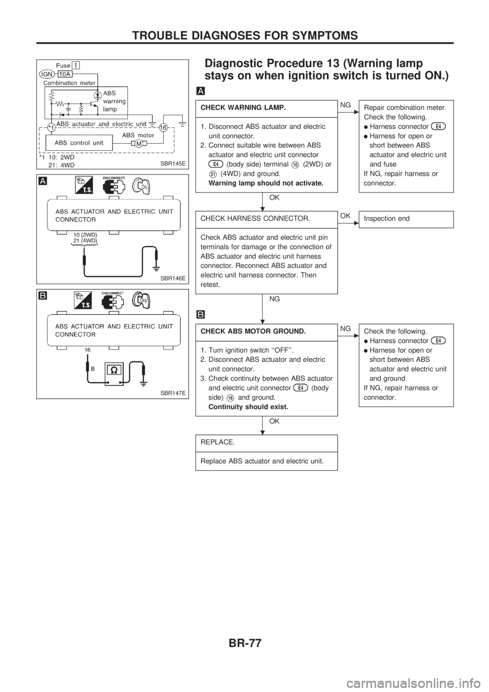
Diagnostic Procedure 13 (Warning lamp
stays on when ignition switch is turned ON.)
CHECK WARNING LAMP.
-------------------------------------------------------------------------------------------------------------------------------------------------------------------------------------------------------------------------------------------------------------------------------------------------------------
1. Disconnect ABS actuator and electric
unit connector.
2. Connect suitable wire between ABS
actuator and electric unit connector
E4(body side) terminalV10(2WD) or
V21(4WD) and ground.
Warning lamp should not activate.
OK
cNG
Repair combination meter.
Check the following.
lHarness connectorE4
lHarness for open or
short between ABS
actuator and electric unit
and fuse
If NG, repair harness or
connector.
CHECK HARNESS CONNECTOR.
-------------------------------------------------------------------------------------------------------------------------------------------------------------------------------------------------------------------------------------------------------------------------------------------------------------
Check ABS actuator and electric unit pin
terminals for damage or the connection of
ABS actuator and electric unit harness
connector. Reconnect ABS actuator and
electric unit harness connector. Then
retest.
NG
cOK
Inspection end
CHECK ABS MOTOR GROUND.
-------------------------------------------------------------------------------------------------------------------------------------------------------------------------------------------------------------------------------------------------------------------------------------------------------------
1. Turn ignition switch ``OFF''.
2. Disconnect ABS actuator and electric
unit connector.
3. Check continuity between ABS actuator
and electric unit connector
E4(body
side)
V16and ground.
Continuity should exist.
OK
cNG
Check the following.
lHarness connectorE4
lHarness for open or
short between ABS
actuator and electric unit
and ground
If NG, repair harness or
connector.
REPLACE.
-------------------------------------------------------------------------------------------------------------------------------------------------------------------------------------------------------------------------------------------------------------------------------------------------------------
Replace ABS actuator and electric unit.
SBR145E
SBR146E
SBR147E
.
.
.
TROUBLE DIAGNOSES FOR SYMPTOMS
BR-77
Page 84 of 1659

Inspection and Adjustment
DISC BRAKEUnit: mm (in)
Brake model CL28VD
Pad wear limit
Minimum thickness 2.0 (0.079)
Rotor repair limit
Minimum thickness 24.0 (0.945)
DRUM BRAKEUnit: mm (in)
Brake model LT26B LT30A
Lining wear limit
Minimum thickness 1.5 (0.059)
Drum repair limit
Maximum inner
diameter261.5 (10.30) 296.5 (11.67)
Out-of-round limit 0.15 (0.0059)
BRAKE PEDALUnit: mm (in)
Free height ``H''*
LHD 209 - 219 (8.23 - 8.62)
RHD 203 - 213 (7.99 - 8.39)
Depressed height ``D''
[under force of 490 N (50
kg, 110 lb) with engine run-
ning]120.0 (4.72)
Clearance ``C'' between
pedal stopper and threaded
end of stop lamp switch0.3 - 1.0 (0.012 - 0.039)
Pedal free play
At clevis 1.0 - 3.0 (0.039 - 0.118)
At pedal pad 4 - 12 (0.16 - 0.47)
*: Measured from surface of melt sheet to pedal pad.
PARKING BRAKE CONTROL
Control type Stick lever Center lever
Lever stroke
[under force of 196 N
(20 kg, 44 lb)]2WD 8 - 10 Ð
4WD 10-12 8-10
Lever stroke when warning
switch comes on1
SERVICE DATA AND SPECIFICATIONS (SDS)
BR-80