Page 35 of 1659
Removal and Installation
lBe careful not to damage cable.
lMake sure there is no free play after installation.
Inspection
1. Check control lever for wear or other damage. Replace if
necessary.
2. Check wires for discontinuity or deterioration. Replace if nec-
essary.
3. Check warning lamp and switch. Correct if necessary.
4. Check part at each connecting portion and, if found deformed
or damaged, replace.
Adjustment
Adjust parking brake as follows:
1. Fully release parking brake lever.
2. Loosen
VAand rotateVBuntil parking brake cable loosen.
3. Depress brake pedal several times until clicking sound does
not occur from rear brakes.
4. Adjust clearance between rear brake shoe and drum.
5. Adjust parking brake lever stroke by rotating
VB.
6. Pull parking brake lever with specified force. Check lever
stroke and ensure smooth operation.
7. Readjust clearance between rear brake shoe and drum.
SBR980D
SBR981D
SBR977D
PARKING BRAKE CONTROL
BR-31
Page 36 of 1659
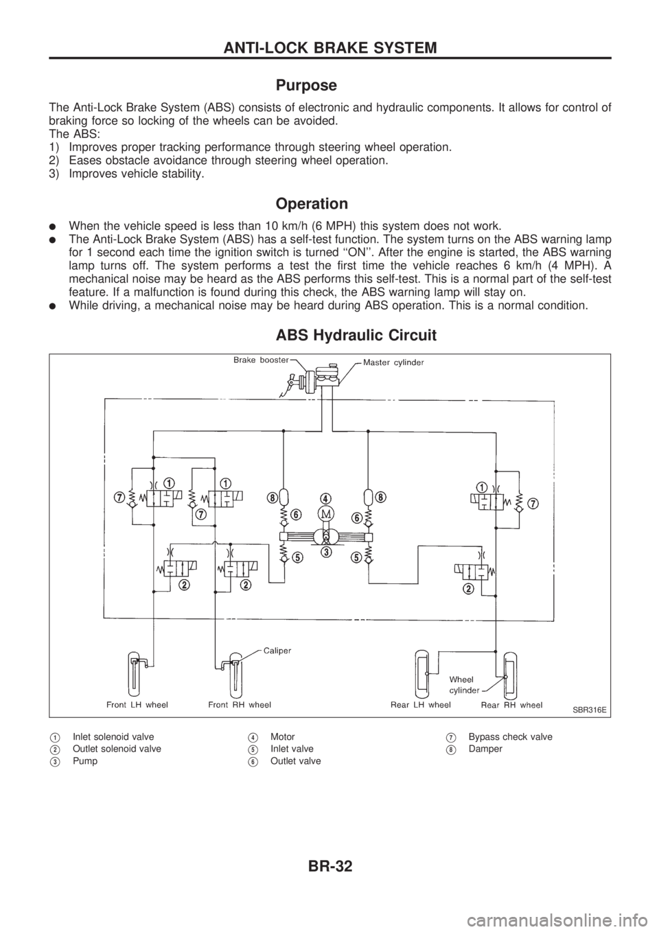
Purpose
The Anti-Lock Brake System (ABS) consists of electronic and hydraulic components. It allows for control of
braking force so locking of the wheels can be avoided.
The ABS:
1) Improves proper tracking performance through steering wheel operation.
2) Eases obstacle avoidance through steering wheel operation.
3) Improves vehicle stability.
Operation
lWhen the vehicle speed is less than 10 km/h (6 MPH) this system does not work.
lThe Anti-Lock Brake System (ABS) has a self-test function. The system turns on the ABS warning lamp
for 1 second each time the ignition switch is turned ``ON''. After the engine is started, the ABS warning
lamp turns off. The system performs a test the first time the vehicle reaches 6 km/h (4 MPH). A
mechanical noise may be heard as the ABS performs this self-test. This is a normal part of the self-test
feature. If a malfunction is found during this check, the ABS warning lamp will stay on.
lWhile driving, a mechanical noise may be heard during ABS operation. This is a normal condition.
ABS Hydraulic Circuit
V1Inlet solenoid valve
V2Outlet solenoid valve
V3Pump
V4Motor
V5Inlet valve
V6Outlet valve
V7Bypass check valve
V8Damper
SBR316E
ANTI-LOCK BRAKE SYSTEM
BR-32
Page 37 of 1659

System Components
System Description
WHEEL SENSOR
The sensor unit consists of a gear-shaped sensor rotor and a
sensor element. The element contains a bar magnet around
which a coil is wound. The sensor is installed on the back of the
brake rotor and the front of the differential (2WD) or the back of
the rear brake drum (4WD). As the wheel rotates, the sensor
generates a sine-wave pattern. The frequency and voltage
increase(s) as the rotating speed increases.
CONTROL UNIT (built in ABS actuator and electric
unit)
The control unit computes the wheel rotating speed by the sig-
nal current sent from the sensor. Then it supplies a DC current
to the actuator solenoid valve. It also controls ON-OFF operation
of the valve relay and motor relay. If any electrical malfunction
should be detected in the system, the control unit causes the
warning lamp to light up. In this condition, the ABS will be deac-
tivated by the control unit, and the vehicle's brake system reverts
to normal operation. (For control unit layout, refer to ABS
ACTUATOR AND ELECTRIC UNIT, BR-34.)
SBR068E
SBR069E
ANTI-LOCK BRAKE SYSTEM
BR-33
Page 43 of 1659
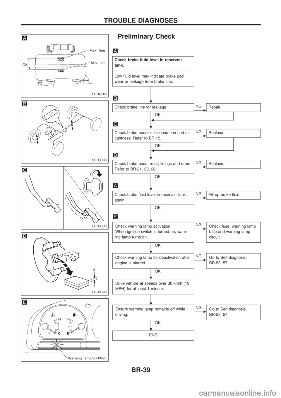
Preliminary Check
Check brake fluid level in reservoir
tank.
-------------------------------------------------------------------------------------------------------------------------------------------------------------------------------------------------------------------------------------------------------------------------------------------------------------
Low fluid level may indicate brake pad
wear or leakage from brake line.
Check brake line for leakage.
OKcNG
Repair.
b
Check brake booster for operation and air
tightness. Refer to BR-15.
OK
cNG
Replace.
b
Check brake pads, rotor, linings and drum.
Refer to BR-21, 23, 28.
OK
cNG
Replace.
Check brake fluid level in reservoir tank
again.
OK
cNG
Fill up brake fluid.
Check warning lamp activation.
When ignition switch is turned on, warn-
ing lamp turns on.
OK
cNG
Check fuse, warning lamp
bulb and warning lamp
circuit.
Check warning lamp for deactivation after
engine is started.
OK
cNG
Go to Self-diagnosis,
BR-53, 57.
Drive vehicle at speeds over 30 km/h (19
MPH) for at least 1 minute.
Ensure warning lamp remains off while
driving.
OK
cNG
Go to Self-diagnosis,
BR-53, 57.
END
SBR451D
SBR389C
SBR058C
SBR059C
SBR069E
.
.
.
.
.
.
.
.
.
TROUBLE DIAGNOSES
BR-39
Page 57 of 1659
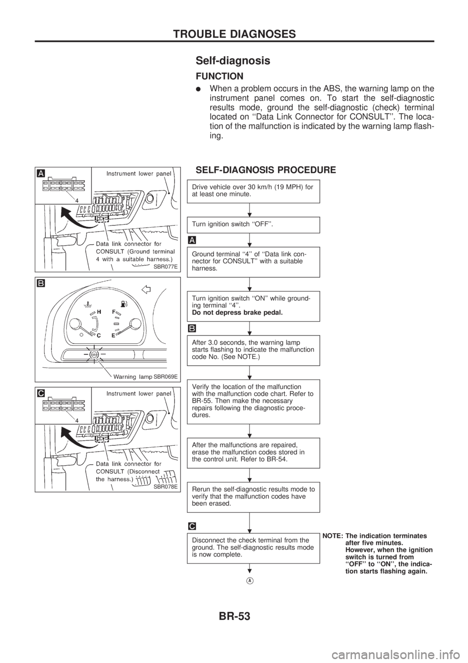
Self-diagnosis
FUNCTION
lWhen a problem occurs in the ABS, the warning lamp on the
instrument panel comes on. To start the self-diagnostic
results mode, ground the self-diagnostic (check) terminal
located on ``Data Link Connector for CONSULT''. The loca-
tion of the malfunction is indicated by the warning lamp flash-
ing.
SELF-DIAGNOSIS PROCEDURE
Drive vehicle over 30 km/h (19 MPH) for
at least one minute.
Turn ignition switch ``OFF''.
Ground terminal ``4'' of ``Data link con-
nector for CONSULT'' with a suitable
harness.
Turn ignition switch ``ON'' while ground-
ing terminal ``4''.
Do not depress brake pedal.
After 3.0 seconds, the warning lamp
starts flashing to indicate the malfunction
code No. (See NOTE.)
Verify the location of the malfunction
with the malfunction code chart. Refer to
BR-55. Then make the necessary
repairs following the diagnostic proce-
dures.
After the malfunctions are repaired,
erase the malfunction codes stored in
the control unit. Refer to BR-54.
Rerun the self-diagnostic results mode to
verify that the malfunction codes have
been erased.
Disconnect the check terminal from the
ground. The self-diagnostic results mode
is now complete.NOTE: The indication terminates
after five minutes.
However, when the ignition
switch is turned from
``OFF'' to ``ON'', the indica-
tion starts flashing again.
VA
SBR077E
SBR069E
SBR078E
.
.
.
.
.
.
.
.
.
TROUBLE DIAGNOSES
BR-53
Page 58 of 1659
VA
Check warning lamp for deactivation
after driving vehicle over 30 km/h (19
MPH) for at least one minute.
After making certain that warning lamp
does not come on, test the ABS in a
safe area to verify that it functions prop-
erly.
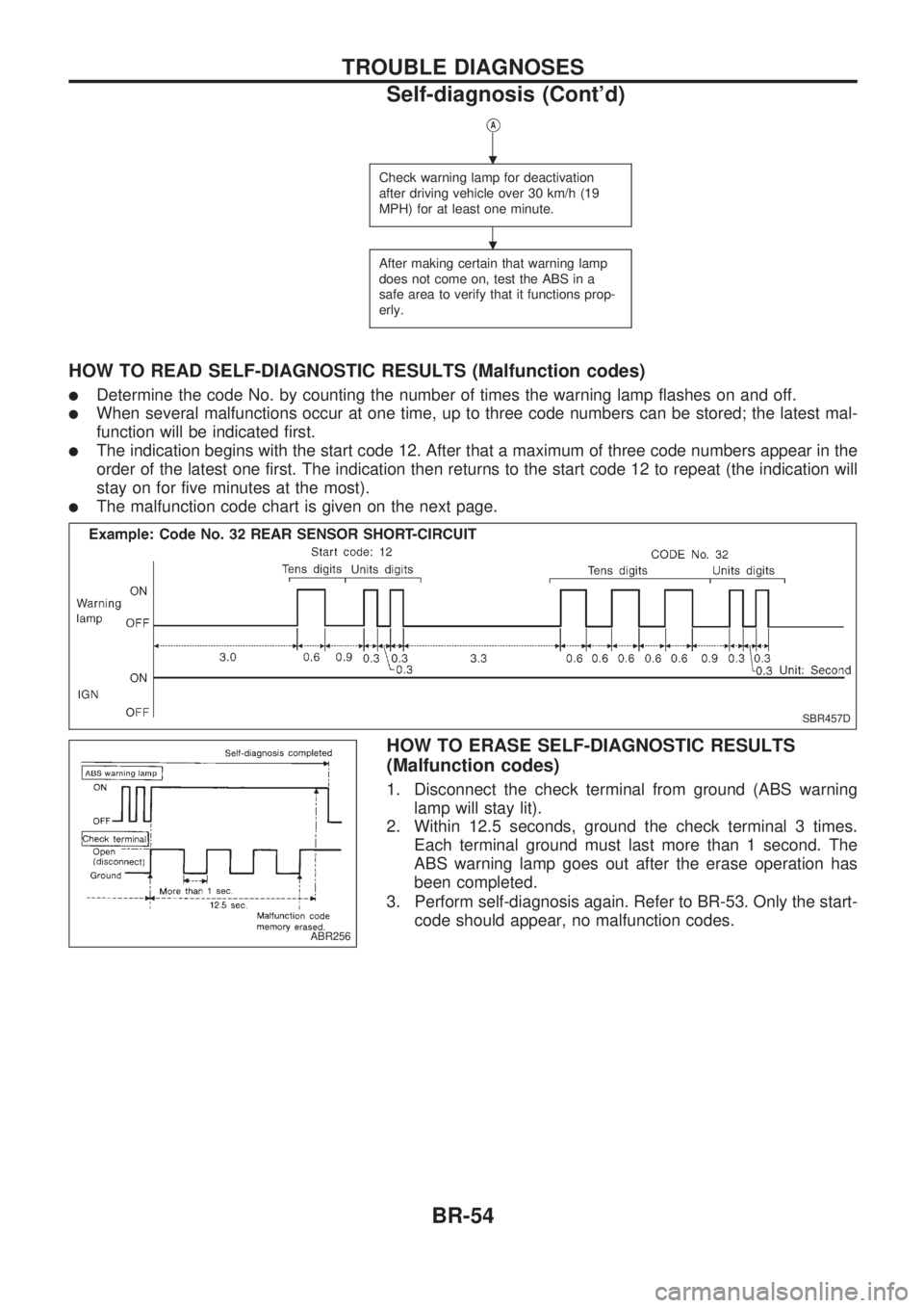
HOW TO READ SELF-DIAGNOSTIC RESULTS (Malfunction codes)
lDetermine the code No. by counting the number of times the warning lamp flashes on and off.
lWhen several malfunctions occur at one time, up to three code numbers can be stored; the latest mal-
function will be indicated first.
lThe indication begins with the start code 12. After that a maximum of three code numbers appear in the
order of the latest one first. The indication then returns to the start code 12 to repeat (the indication will
stay on for five minutes at the most).
lThe malfunction code chart is given on the next page.
HOW TO ERASE SELF-DIAGNOSTIC RESULTS
(Malfunction codes)
1. Disconnect the check terminal from ground (ABS warning
lamp will stay lit).
2. Within 12.5 seconds, ground the check terminal 3 times.
Each terminal ground must last more than 1 second. The
ABS warning lamp goes out after the erase operation has
been completed.
3. Perform self-diagnosis again. Refer to BR-53. Only the start-
code should appear, no malfunction codes.
SBR457D
ABR256
.
.
TROUBLE DIAGNOSES
Self-diagnosis (Cont'd)
BR-54
Page 59 of 1659

MALFUNCTION CODE/SYMPTOM CHART
Code No.
(No. of warning lamp flashes)Malfunctioning part Diagnostic procedure
45 Actuator front left outlet solenoid valve 2
46 Actuator front left inlet solenoid valve 2
41 Actuator front right outlet solenoid valve 2
42 Actuator front right inlet solenoid valve 2
55 Actuator rear outlet solenoid valve 2
56 Actuator rear inlet solenoid valve 2
25.3 Front left sensor (open-circuit) 1
26.3 Front left sensor (short-circuit) 1
21.3 Front right sensor (open-circuit) 1
22.3 Front right sensor (short-circuit) 1
35.1,.3 Rear sensor (open-circuit) 1
36.1,.3 Rear sensor (short-circuit) 1
31.2,.3 Rear right sensor (open-circuit) 1
32.2,.3 Rear right sensor (short-circuit) 1
35.2,.3 Rear left sensor (open-circuit) 1
36.2,.3 Rear left sensor (short-circuit) 1
18.3 Sensor rotor 1
17.2 G sensor and circuit 5
61.5 Actuator motor or motor relay 3
63 Solenoid valve relay 2
57.4 Power supply (Low voltage) 4
71 Control unit 6
Warning lamp stays on when igni-
tion switch is turned onControl unit power supply circuit
Warning lamp bulb circuit
Control unit or control unit connector
Solenoid valve relay stuck
Power supply for solenoid valve relay coil13
Warning lamp does not come on
when ignition switch is turned onFuse, warning lamp bulb or warning lamp circuit
Control unit12
Pedal vibration and noise Ð 11
Long stopping distance Ð 9
Unexpected pedal action Ð 8
ABS does not work Ð 10
ABS works frequently Ð 7
.1: 2WD model only
.2: 4WD model only
.3: If one or more wheels spin on a rough or slippery road for 40 seconds or more, the ABS warning lamp will illuminate. This does
not indicate a malfunction. Only in the case of the short-circuit (Code Nos. 26, 22, 32 and 36), after repair the ABS warning
lamp also illuminates when the ignition switch is turned ``ON''. In this case, drive the vehicle at speeds greater than 30 km/h (19
MPH) for approximately 1 minute as specified in ``SELF-DIAGNOSIS PROCEDURE'', BR-53. Check to ensure that the ABS
warning lamp goes out while the vehicle is being driven.
.4: The trouble code ``57'', which refers to a low power supply voltage, does not indicate that the ABS control unit is malfunctioning.
Do not replace the ABS control unit with a new one.
.5: The trouble code ``61'' can sometimes appear when the ABS motor is not properly grounded. If it appears, be sure to check the
condition of the ABS motor ground circuit connection.
TROUBLE DIAGNOSES
Self-diagnosis (Cont'd)
BR-55
Page 60 of 1659
CONSULT
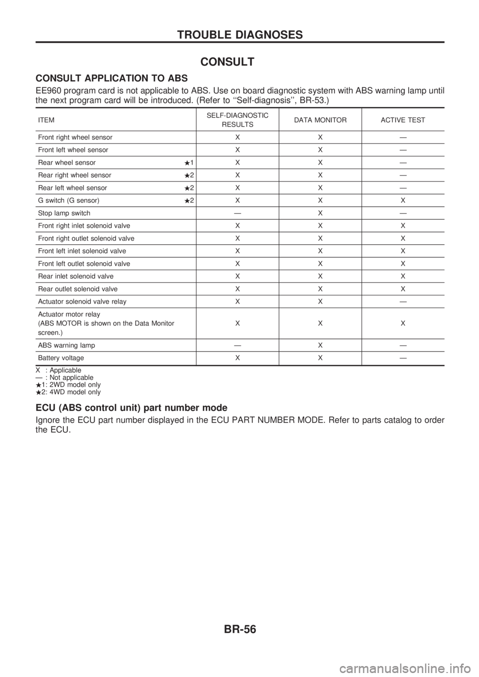
CONSULT APPLICATION TO ABS
EE960 program card is not applicable to ABS. Use on board diagnostic system with ABS warning lamp until
the next program card will be introduced. (Refer to ``Self-diagnosis'', BR-53.)
ITEMSELF-DIAGNOSTIC
RESULTSDATA MONITOR ACTIVE TEST
Front right wheel sensor X X Ð
Front left wheel sensor X X Ð
Rear wheel sensor.1X X Ð
Rear right wheel sensor.2X X Ð
Rear left wheel sensor.2X X Ð
G switch (G sensor).2XXX
Stop lamp switch Ð X Ð
Front right inlet solenoid valve X X X
Front right outlet solenoid valve X X X
Front left inlet solenoid valve X X X
Front left outlet solenoid valve X X X
Rear inlet solenoid valve X X X
Rear outlet solenoid valve X X X
Actuator solenoid valve relay X X Ð
Actuator motor relay
(ABS MOTOR is shown on the Data Monitor
screen.)XXX
ABS warning lamp Ð X Ð
Battery voltage X X Ð
X : Applicable
Ð : Not applicable
.1: 2WD model only
.2: 4WD model only
ECU (ABS control unit) part number mode
Ignore the ECU part number displayed in the ECU PART NUMBER MODE. Refer to parts catalog to order
the ECU.
TROUBLE DIAGNOSES
BR-56