Page 408 of 1659

CAUTION:
If it becomes necessary to start the engine with a booster
battery and jumper cables,
a. Use a 12-volt booster battery.
b. After connecting battery cables, ensure that they are
tightly clamped to battery terminals for good contact.
c. Never add distilled water through the hole used to check
specific gravity.
How to Handle Battery
METHODS OF PREVENTING OVER-DISCHARGE
The following precautions must be taken to prevent over-dis-
charging a battery.
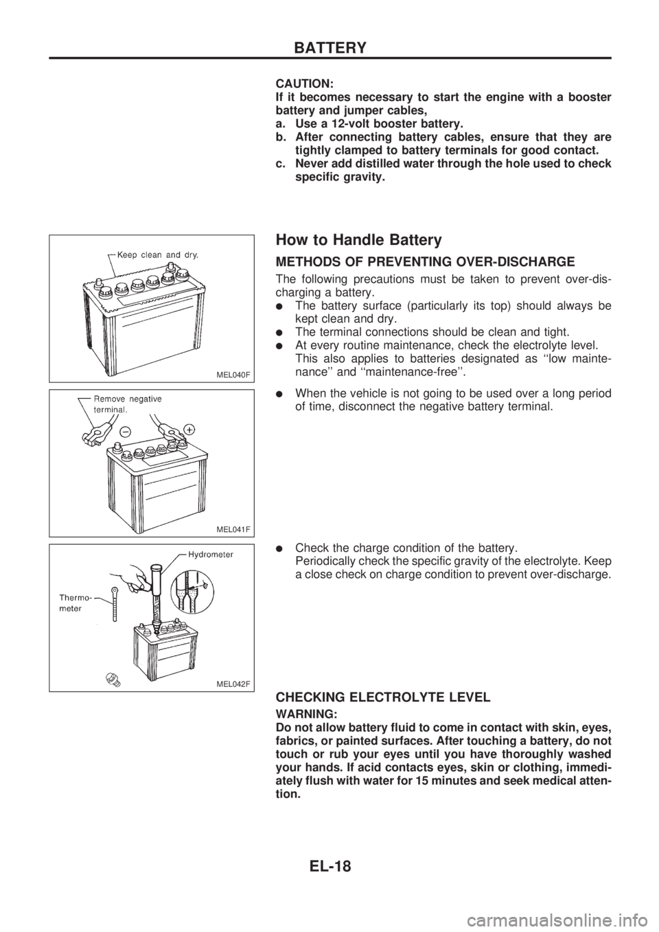
lThe battery surface (particularly its top) should always be
kept clean and dry.
lThe terminal connections should be clean and tight.
lAt every routine maintenance, check the electrolyte level.
This also applies to batteries designated as ``low mainte-
nance'' and ``maintenance-free''.
lWhen the vehicle is not going to be used over a long period
of time, disconnect the negative battery terminal.
lCheck the charge condition of the battery.
Periodically check the specific gravity of the electrolyte. Keep
a close check on charge condition to prevent over-discharge.
CHECKING ELECTROLYTE LEVEL
WARNING:
Do not allow battery fluid to come in contact with skin, eyes,
fabrics, or painted surfaces. After touching a battery, do not
touch or rub your eyes until you have thoroughly washed
your hands. If acid contacts eyes, skin or clothing, immedi-
ately flush with water for 15 minutes and seek medical atten-
tion.
MEL040F
MEL041F
MEL042F
BATTERY
EL-18
Page 426 of 1659

Trouble Diagnoses
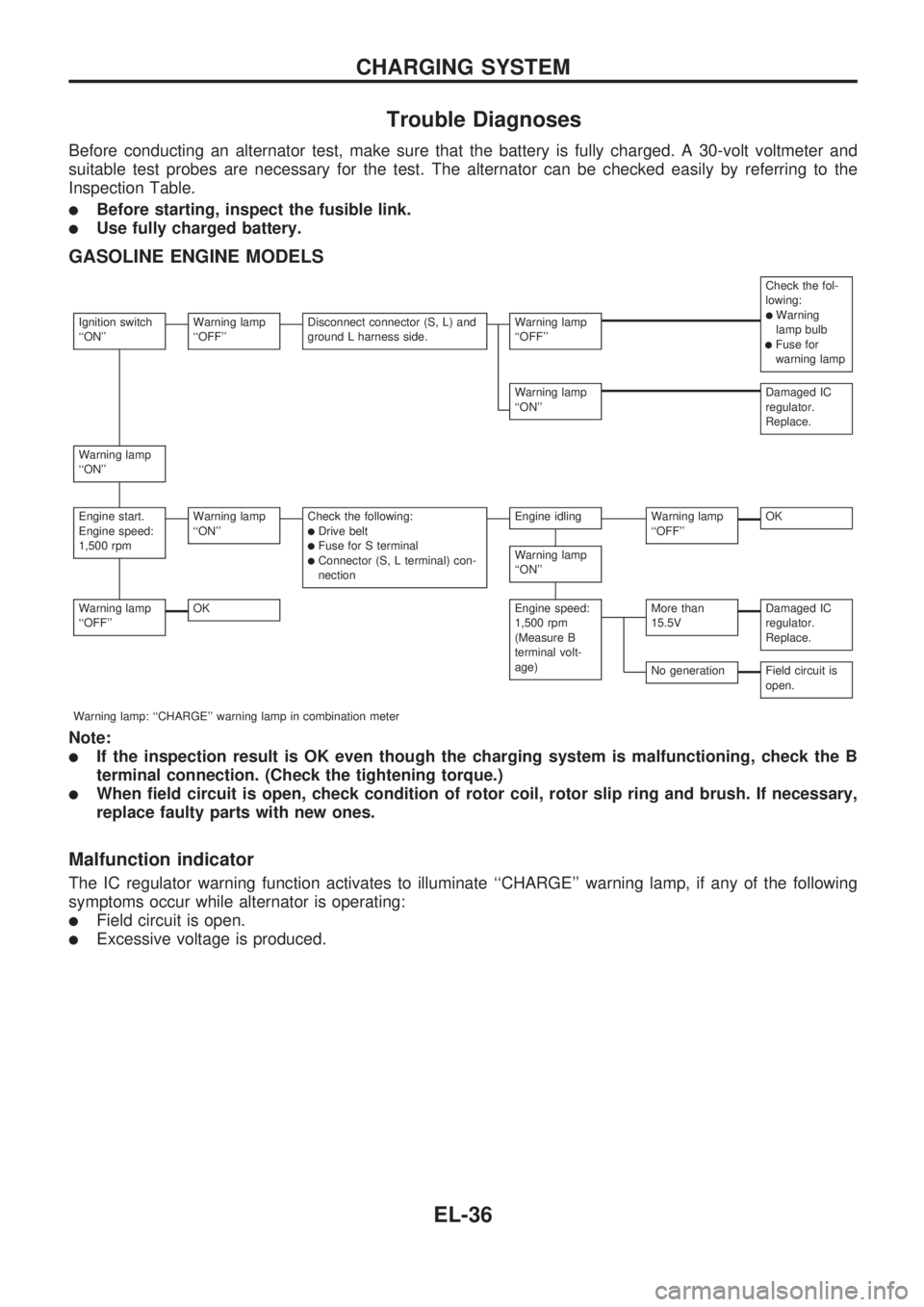
Before conducting an alternator test, make sure that the battery is fully charged. A 30-volt voltmeter and
suitable test probes are necessary for the test. The alternator can be checked easily by referring to the
Inspection Table.
lBefore starting, inspect the fusible link.
lUse fully charged battery.
GASOLINE ENGINE MODELS
Check the fol-
lowing:
lWarning
lamp bulb
lFuse for
warning lamp
Ignition switch
``ON''Warning lamp
``OFF''Disconnect connector (S, L) and
ground L harness side.Warning lamp
``OFF''
Warning lamp
``ON''Damaged IC
regulator.
Replace.
Warning lamp
``ON''
Engine start.
Engine speed:
1,500 rpmWarning lamp
``ON''Check the following:lDrive beltlFuse for S terminallConnector (S, L terminal) con-
nection
Engine idlingWarning lamp
``OFF''OK
Warning lamp
``ON''
Warning lamp
``OFF''OKEngine speed:
1,500 rpm
(Measure B
terminal volt-
age)More than
15.5VDamaged IC
regulator.
Replace.
No generationField circuit is
open.
Warning lamp: ``CHARGE'' warning lamp in combination meter
Note:
lIf the inspection result is OK even though the charging system is malfunctioning, check the B
terminal connection. (Check the tightening torque.)
lWhen field circuit is open, check condition of rotor coil, rotor slip ring and brush. If necessary,
replace faulty parts with new ones.
Malfunction indicator
The IC regulator warning function activates to illuminate ``CHARGE'' warning lamp, if any of the following
symptoms occur while alternator is operating:
lField circuit is open.
lExcessive voltage is produced.
CHARGING SYSTEM
EL-36
Page 427 of 1659
DIESEL ENGINE MODELS
Check the fol-
lowing:
lWarning
lamp bulb
lFuse for
warning lamp
Ignition switch
``ON''Warning lamp
``OFF''Disconnect connector (S, L) and
ground L harness side.Warning lamp
``OFF''
Warning lamp
``ON''Damaged IC
regulator.
Replace.
Warning lamp
``ON''
Engine idlingWarning lamp
``ON''Check the fol-
lowing:
lDrive beltlField circuit
Check the fol-
lowing:
lFuse for S
terminal
lOpen circuit
for S terminal
lIC regulator
Warning lamp
``OFF''Engine speed: 1,500 rpm
(Measure B terminal voltage)More than
15.5V
13 - 15VOK
Warning lamp: ``CHARGE'' warning lamp in combination meter
Note:
lIf the inspection result is OK even though the charging system is malfunctioning, check the B
terminal connection (check the tightening torque).
lWhen field circuit is open, check condition of rotor coil, rotor slip ring and brush. If necessary,
replace faulty parts with new ones.
CHARGING SYSTEM
Trouble Diagnoses (Cont'd)
EL-37
Page 464 of 1659
Schematic
HEL340A
TURN SIGNAL AND HAZARD WARNING LAMPS
EL-74
Page 465 of 1659
Wiring Diagram Ð TURN Ð/Except 4WD
Models for Europe
HEL426A
TURN SIGNAL AND HAZARD WARNING LAMPS
EL-75
Page 466 of 1659
HEL427A
TURN SIGNAL AND HAZARD WARNING LAMPS
Wiring Diagram Ð TURN Ð/Except 4WD
Models for Europe (Cont'd)
EL-76
Page 467 of 1659
Wiring Diagram Ð TURN Ð/4WD Models for
Europe
NOTE: For Single cab models with air bag, refer to ``Wiring Diagram Ð TURN Ð/Except
4WD Models for Europe''.
HEL341A
TURN SIGNAL AND HAZARD WARNING LAMPS
EL-77
Page 468 of 1659
HEL342A
TURN SIGNAL AND HAZARD WARNING LAMPS
Wiring Diagram Ð TURN Ð/4WD Models for
Europe (Cont'd)
EL-78