Page 508 of 1659
Wiring diagram Ð BUZZER Ð/RHD Models
for Europe
LIGHT WARNING BUZZER
HEL371A
WARNING BUZZER
EL-118
Page 509 of 1659
Electrical Components Inspection
FUEL FILTER WARNING BUZZER CHECK
LIGHT WARNING BUZZER
1. Apply 12V direct current to warning buzzer unit terminalsV10
andV4.
Warning buzzer should sound.
2. Apply 12V direct current to warning buzzer unit terminals
V10,
V11andV4.
Warning buzzer should not sound.
GEL208
SEL644V
SEL645V
WARNING BUZZER
EL-119
Page 563 of 1659

System Description
FUNCTION
Multi-remote control system has the following function.
lDoor lock
lDoor unlock
lHazard reminder
LOCK OPERATION
To lock door by multi-remote controller, the following two signals must be received.
lKey switch OFF (when ignition key is not in ignition key cylinder.)
lAll door switches CLOSED
When the LOCK signal is input to multi-remote control unit (the antenna of the system is combined with
multi-remote control unit), ground is supplied
lthrough multi-remote control unit terminalV10
lto door lock timer terminalV5and
lto multi-remote control relay-3 (LOCK) terminalV1.
Then door lock timer operates to lock doors (except for driver's door) and mutli-remote control relay-3
(LOCK) energized to lock driver's door.
UNLOCK OPERATION
To unlock door by multi-remote controller, the following signal must be received.
lKey switch OFF (when ignition key is not in ignition key cylinder)
When the UNLOCK signal is input to multi-remote control unit (the antenna of the system is combined with
multi-remote control unit), ground is supplied
lthrough multi-remote control unit terminalV11
lto door lock timer terminalV8and
lto multi-remote control relay-4 (UNLOCK) terminalV1.
Then door lock timer operates to unlock doors (except for driver's door) and mutli-remote control relay-4
(UNLOCK) is energized to unlock driver's door.
HAZARD REMINDER
When the doors and locked or unlocked by multi-remote controller, ground is supplied
lto terminalV1of multi-remote control relay-1 and 2
lthrough multi-remote control unit terminalV12.
Then the relays are energized and hazard warning lamp flashes as follows
lLock operation: Flash once
lUnlock operation: Flash twice
MULTI-REMOTE CONTROLLER ID CODE ENTRY
A maximum of four remote controllers can be entered. Any attempt to enter a remote controller will erase
all ID codes previously entered. Therefore, be sure to receive all remote controllers from the vehicle owner
when any ID code entry is performed.
To enter ID code entry, the following signals must be input to the multi-remote control unit.
lDriver side LOCKED signal (from driver side door unlock sensor)
lDoor switch CLOSED signal
lKey switch signal (INSERTED/WITHDRAWN)
lAccessory power supply
lSignal from remote controller
For detailed procedure, refer to ``ID Code Entry Procedure'' in EL-182.
MULTI-REMOTE CONTROL SYSTEM/FOR EUROPE
EL-173
Page 572 of 1659

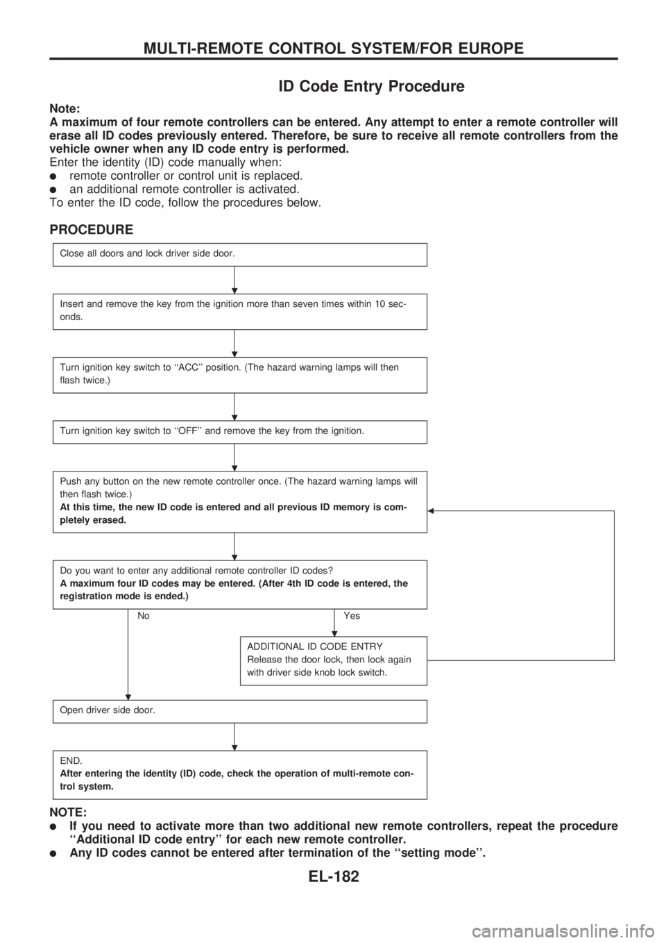
ID Code Entry Procedure
Note:
A maximum of four remote controllers can be entered. Any attempt to enter a remote controller will
erase all ID codes previously entered. Therefore, be sure to receive all remote controllers from the
vehicle owner when any ID code entry is performed.
Enter the identity (ID) code manually when:
lremote controller or control unit is replaced.
lan additional remote controller is activated.
To enter the ID code, follow the procedures below.
PROCEDURE
Close all doors and lock driver side door.
Insert and remove the key from the ignition more than seven times within 10 sec-
onds.
Turn ignition key switch to ``ACC'' position. (The hazard warning lamps will then
flash twice.)
Turn ignition key switch to ``OFF'' and remove the key from the ignition.
Push any button on the new remote controller once. (The hazard warning lamps will
then flash twice.)
At this time, the new ID code is entered and all previous ID memory is com-
pletely erased.
b
Do you want to enter any additional remote controller ID codes?
A maximum four ID codes may be entered. (After 4th ID code is entered, the
registration mode is ended.)
No Yes
ADDITIONAL ID CODE ENTRY
Release the door lock, then lock again
with driver side knob lock switch.
Open driver side door.
END.
After entering the identity (ID) code, check the operation of multi-remote con-
trol system.
NOTE:
lIf you need to activate more than two additional new remote controllers, repeat the procedure
``Additional ID code entry'' for each new remote controller.
lAny ID codes cannot be entered after termination of the ``setting mode''.
.
.
.
.
.
.
.
.
MULTI-REMOTE CONTROL SYSTEM/FOR EUROPE
EL-182
Page 643 of 1659

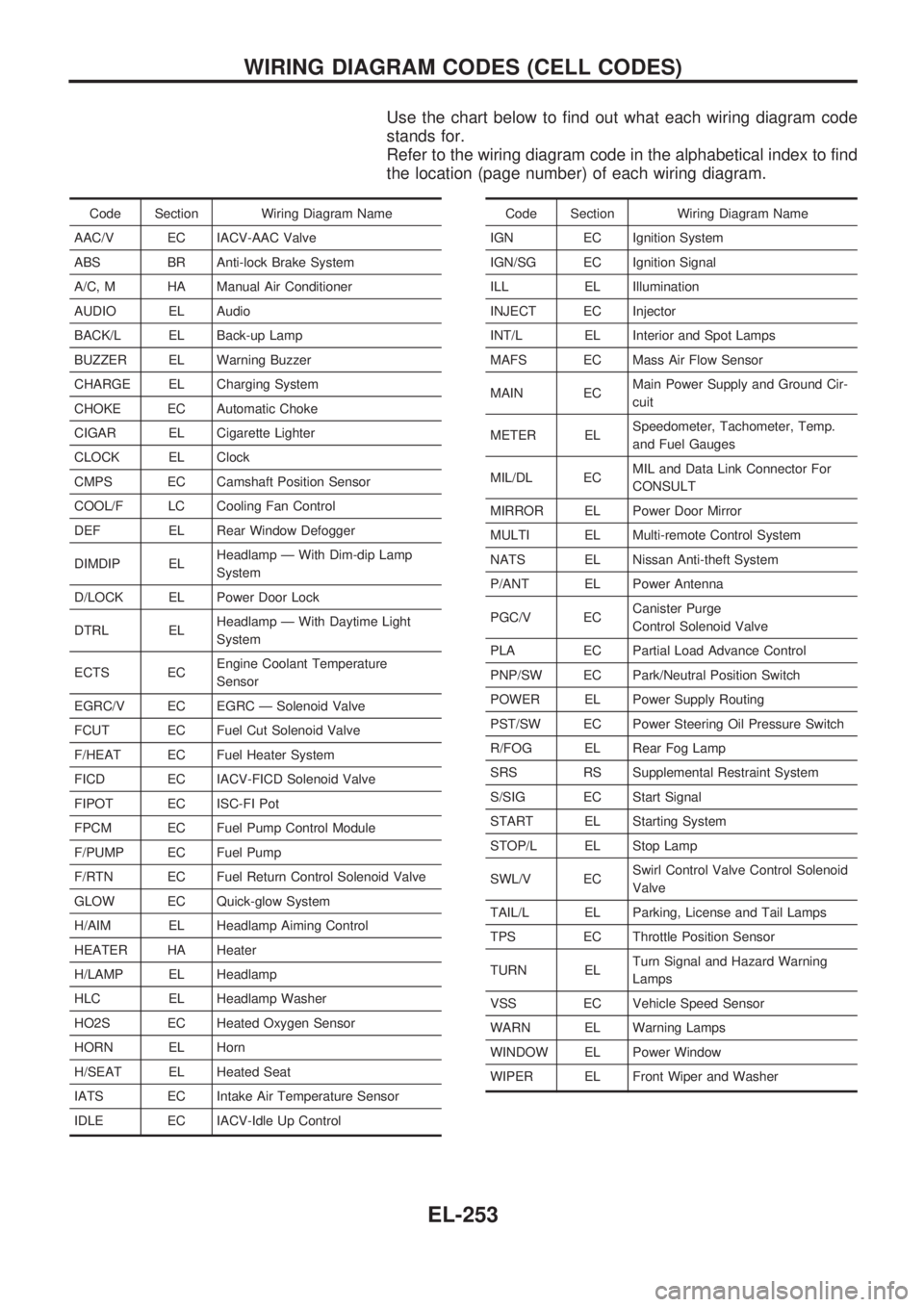
Use the chart below to find out what each wiring diagram code
stands for.
Refer to the wiring diagram code in the alphabetical index to find
the location (page number) of each wiring diagram.
Code Section Wiring Diagram Name
AAC/V EC IACV-AAC Valve
ABS BR Anti-lock Brake System
A/C, M HA Manual Air Conditioner
AUDIO EL Audio
BACK/L EL Back-up Lamp
BUZZER EL Warning Buzzer
CHARGE EL Charging System
CHOKE EC Automatic Choke
CIGAR EL Cigarette Lighter
CLOCK EL Clock
CMPS EC Camshaft Position Sensor
COOL/F LC Cooling Fan Control
DEF EL Rear Window Defogger
DIMDIP ELHeadlamp Ð With Dim-dip Lamp
System
D/LOCK EL Power Door Lock
DTRL ELHeadlamp Ð With Daytime Light
System
ECTS ECEngine Coolant Temperature
Sensor
EGRC/V EC EGRC Ð Solenoid Valve
FCUT EC Fuel Cut Solenoid Valve
F/HEAT EC Fuel Heater System
FICD EC IACV-FICD Solenoid Valve
FIPOT EC ISC-FI Pot
FPCM EC Fuel Pump Control Module
F/PUMP EC Fuel Pump
F/RTN EC Fuel Return Control Solenoid Valve
GLOW EC Quick-glow System
H/AIM EL Headlamp Aiming Control
HEATER HA Heater
H/LAMP EL Headlamp
HLC EL Headlamp Washer
HO2S EC Heated Oxygen Sensor
HORN EL Horn
H/SEAT EL Heated Seat
IATS EC Intake Air Temperature Sensor
IDLE EC IACV-Idle Up ControlCode Section Wiring Diagram Name
IGN EC Ignition System
IGN/SG EC Ignition Signal
ILL EL Illumination
INJECT EC Injector
INT/L EL Interior and Spot Lamps
MAFS EC Mass Air Flow Sensor
MAIN ECMain Power Supply and Ground Cir-
cuit
METER ELSpeedometer, Tachometer, Temp.
and Fuel Gauges
MIL/DL ECMIL and Data Link Connector For
CONSULT
MIRROR EL Power Door Mirror
MULTI EL Multi-remote Control System
NATS EL Nissan Anti-theft System
P/ANT EL Power Antenna
PGC/V ECCanister Purge
Control Solenoid Valve
PLA EC Partial Load Advance Control
PNP/SW EC Park/Neutral Position Switch
POWER EL Power Supply Routing
PST/SW EC Power Steering Oil Pressure Switch
R/FOG EL Rear Fog Lamp
SRS RS Supplemental Restraint System
S/SIG EC Start Signal
START EL Starting System
STOP/L EL Stop Lamp
SWL/V ECSwirl Control Valve Control Solenoid
Valve
TAIL/L EL Parking, License and Tail Lamps
TPS EC Throttle Position Sensor
TURN ELTurn Signal and Hazard Warning
Lamps
VSS EC Vehicle Speed Sensor
WARN EL Warning Lamps
WINDOW EL Power Window
WIPER EL Front Wiper and Washer
WIRING DIAGRAM CODES (CELL CODES)
EL-253
Page 681 of 1659
WARNING:
lPosition vehicle on a flat and solid surface.
lPlace chocks at front and back of rear wheels.
lDo not remove engine until exhaust system has com-
pletely cooled off.
Otherwise, you may burn yourself and/or fire may break
out in fuel line.
lBefore disconnecting fuel hose, release fuel pressure.
Refer to EC section (``Fuel Pressure Release'').
lBe sure to hoist engine and transmission in a safe man-
ner.
lFor engines not equipped with engine slingers, attach
proper slingers and bolts described in PARTS CATA-
LOG.
CAUTION:
lWhen lifting engine, be sure to clear surrounding parts.
Take special care near accelerator wire casing, brake
lines and brake master cylinder.
lIn lifting the engine, always use engine slingers in a safe
manner.
lFor 4WD models, apply sealant between engine and
transmission. Refer to MT section (``Removal and Instal-
lation'').
SEM601FA
ENGINE REMOVALKA
EM-36
Page 697 of 1659

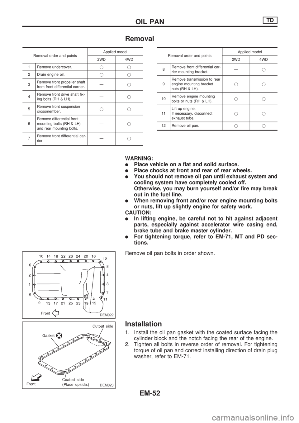
Removal
Removal order and pointsApplied model
2WD 4WD
1 Remove undercover.jj
2 Drain engine oil.jj
3Remove front propeller shaft
from front differential carrier.Ðj
4Remove front drive shaft fix-
ing bolts (RH & LH).Ðj
5Remove front suspension
crossmember.jj
6Remove differential front
mounting bolts (RH & LH)
and rear mounting bolts.Ðj
7Remove front differential car-
rier.ÐjRemoval order and pointsApplied model
2WD 4WD
8Remove front differential car-
rier mounting bracket.Ðj
9Remove transmission to rear
engine mounting bracket
nuts (RH & LH).jj
10Remove engine mounting
bolts or nuts (RH & LH).jj
11Lift up engine.
If necessary, disconnect
exhaust tube.jj
12 Remove oil pan.jj
WARNING:
lPlace vehicle on a flat and solid surface.
lPlace chocks at front and rear of rear wheels.
lYou should not remove oil pan until exhaust system and
cooling system have completely cooled off.
Otherwise, you may burn yourself and/or fire may break
out in the fuel line.
lWhen removing front and/or rear engine mounting bolts
or nuts, lift up slightly engine for safety work.
CAUTION:
lIn lifting engine, be careful not to hit against adjacent
parts, especially against accelerator wire casing end,
brake tube and brake master cylinder.
lFor tightening torque, refer to EM-71, MT and PD sec-
tions.
Remove oil pan bolts in order shown.
Installation
1. Install the oil pan gasket with the coated surface facing the
cylinder block and the notch facing the rear of the engine.
2. Tighten all bolts in reverse order of removal. For tightening
torque of oil pan and correct installing direction of drain plug
washer, refer to EM-71.
DEM022
DEM023
OIL PANTD
EM-52
Page 703 of 1659
REPLACING VALVE SEAT FOR SERVICE PARTS
1. Bore out old seat until it collapses or remove valve seats with
Tool.
Place a copper seat between contact surface of Tool and
cylinder head.
2. If the valve seat for the exhaust side is oversized, machine
its mating area (on the cylinder head side) to the dimensions
indicated in the table below. Refer to the figure at the left for
machining procedures.
Unit: mm (in)
Oversized valve
seatBore diameter ``d''
TD25
0.2 (0.008)38.695 - 38.710
(1.5234 - 1.5240)
0.4 (0.016)38.895 - 38.910
(1.5313 - 1.5319)
3. Place new valve seats on dry ice and allow them to cool for
five minutes.
WARNING:
Do not touch cooled valve seats with bare hand.
4. Heat cylinder head to 80ÉC (176ÉF).
5. Install cooled valve seats on cylinder head with Tool.
6. Stake exhaust valve seat at five places with punch.
When staking valve seat, select different places than those
staked before.
SEM631B
DEM031
SEM632B
SEM087
CYLINDER HEADTD
Inspection (Cont'd)
EM-58