Page 1793 of 1807
TURBOCHARGER
1210 Author�: Date�:
1997 SUPRA (RM502U)
REMOVAL
1. DRAIN ENGINE COOLANT
2.")
TC00E-02
P11430
ClampWire
P11348Arm Bracket Stay
Crossmember
Extension
P12054
TC-10
- TURBOCHARGING (2JZ-GTE)TURBOCHARGER
1210 Author�: Date�:
1997 SUPRA (RM502U)
REMOVAL
1. DRAIN ENGINE COOLANT
2. REMOVE ENGINE UNDER COVER
3. DISCONNECT CRUISE CONTROL ACTUATOR
CABLE FROM THROTTLE BODY
4. REMOVE NO.1 AIR HOSE
5. REMOVE AIR CLEANER DUCT
6. REMOVE AIR CLEANER AND MAF METER
ASSEMBLY
(a) Remove the 3 bolts.
(b) Loosen the hose clamp, disconnect the air hose from the
intake air connector.
(c) Disconnect the MAF meter wire from the clamp on the air
cleaner case.
(d) Disconnect the MAF meter connector, and remove the air
cleaner and MAF meter assembly.
7. DISCONNECT THEFT DETERRENT HORN FROM
BODY
8. REMOVE FRONT LOWER ARM BRACKET STAY
Remove the 2 bolts, nut, plate washer and arm bracket stay.
Torque:
Bolts 44 N´m (450 kgf´cm, 33 ft´lbf)
Nut 59 N´m (600 kgf´cm, 43 ft´lbf)
9. REMOVE UPPER FRONT CROSSMEMBER
EXTENSION
Remove the 2 bolts, 2 nuts and crossmember extension.
Torque:
Bolts 29 N´m (300 kgf´cm, 22 ft´lbf)
Nuts 33 N´m (340 kgf´cm, 25 ft´lbf)
10. REMOVE NO.2 FRONT EXHAUST PIPE
(a) Remove the 2 bolts and nuts holding the front exhaust
pipe to the No.2 front exhaust pipe.
Torque: 58 N´m (590 kgf´cm, 43 ft´lbf)
(b) Remove the 2 bolts and pipe support bracket.
Torque: 43 N´m (440 kgf´cm, 32 ft´lbf)
(c) Disconnect the front exhaust pipe from the No.2 exhaust
pipe. Remove the gasket.
HINT:
At the time of installation, please refer to the following items.
Use a new gasket.
Page 1794 of 1807

(1)
P11403
Engine Wire
(2)(1) Clamp
Clamp
P11402
(2)(1)
Clamp
Clamp
Clamp
- TURBOCHARGING (2JZ-GTE)TURBOCHARGER
TC-1 1
1211 Author�: D")
P12025
P11349
Rear
SideFront
Side
P11444
Engine
Wire
Protector(2)
(1)
P11403
Engine Wire
(2)(1) Clamp
Clamp
P11402
(2)(1)
Clamp
Clamp
Clamp
- TURBOCHARGING (2JZ-GTE)TURBOCHARGER
TC-1 1
1211 Author�: Date�:
1997 SUPRA (RM502U)
(d) Remove the 3 nuts, No.2 front exhaust pipe and gasket.
HINT:
At the time of installation, please refer to the following items.
Use a new gasket and 3 new nuts.
Torque: 62 N´m (630 kgf´cm, 46 ft´lbf)
11. REMOVE HEAT INSULATOR FOR NO.2 FRONT
EXHAUST PIPE
Remove the 2 bolts, 2 nuts and heat insulator.
12. DISCONNECT A/T OIL COOLER TUBES FROM
ENGINE
(a) Remove the bolt and tube clamp, and disconnect the oil
cooler tubes from the bracket (front side) on the genera-
tor.
(b) Remove the bolt and tube clamp, and disconnect the oil
cooler tubes from the bracket (rear side) on the cylinder
block.
(c) Remove the bolt and tube bracket (rear side) from the cyl-
inder block.
13. DISCONNECT ENGINE WIRE PROTECTOR FROM
BODY
Remove the 2 bolts, and disconnect the wire protector from the
body.
14. DISCONNECT HOSES
Disconnect these hoses:
(1) Heater hose from No.3 water bypass pipe
(2) EVAP hose from No.1 vacuum pipe
15. DISCONNECT IAC VALVE PIPE FROM NO.2 AIR
TUBE
(a) Disconnect the engine wire from the clamp.
(b) Disconnect these hoses:
(1) Air hose (from No.1 vacuum pipe) from IAC valve
pipe
(2) Air hose from No.2 air tube
(c) Disconnect the IAC valve pipe from the clamp.
16. DISCONNECT NO.1 VACUUM PIPE FROM AIR
TUBES
(a) Disconnect these connectors:
(1) VSV connector for intake air control valve
(2) VSV connector for exhaust bypass valve
(b) Disconnect the engine wire from the 3 clamps.
Page 1795 of 1807

(3)(1) (8)
(9)
(5)
(4) (6)(7)
P11442
(3)
(1) Clamp
(2)(4)
P11401
(3)
(1) (2)(4)
P11400
No.2 Turbo
Water Pipe TC-12
- TURBOCHARGING (2JZ-GTE)TURBOCHARGER
1212 Author�: Date�:
1997 SUPRA (R")
P11443
(2)
(3)(1) (8)
(9)
(5)
(4) (6)(7)
P11442
(3)
(1) Clamp
(2)(4)
P11401
(3)
(1) (2)(4)
P11400
No.2 Turbo
Water Pipe TC-12
- TURBOCHARGING (2JZ-GTE)TURBOCHARGER
1212 Author�: Date�:
1997 SUPRA (RM502U)
(c) Disconnect these hoses:
(1) Air hose from No.4 air tube
(2) Air hose from No.1 air tube
(3) Air hose (from VSV for waste gate valve) from vacu-
um pipe
(4) Air hose (from VSV for exhaust gas control valve)
from vacuum pipe
(5) Vacuum hose (from air bypass valve) from No.1 air
tube
(6) 2 air hoses (from VSV for exhaust bypass valve)
from vacuum pipe
(7) Air hose (from No.2 air tube) from vacuum pipe
(8) Air hose from VSV for intake air control valve
(9) 2 air hoses (from pressure tank) from vacuum
pipe
(d) Remove the 3 bolts, and disconnect the vacuum pipe
from the air tubes.
17. REMOVE VSV ASSEMBLY
(a) Disconnect these hoses:
(1) Air hose from actuator for waste gate valve
(2) Air hose from actuator for exhaust gas control
valve
(3) Air hose from hose clamp
(4) Engine wire from wire clamp
(b) Remove the 2 bolts.
(c) Disconnect the 2 VSV connectors, and remove the VSV
assembly.
18. REMOVE AIR TUBES AND INTAKE AIR
CONNECTOR
(a) Disconnect the connector and hoses:
(1) Crankshaft position sensor connector from
clamp
(2) Water bypass hose (from water pump) from No.1
turbo water pipe
(3) Water bypass hose (from water outlet) from No.1
turbo water pipe
(4) Water bypass hose (from water outlet) from No.2
turbo water pipe
(b) Remove the bolt, and disconnect the No.2 turbo water
pipe from the No.4 air tube.
Page 1804 of 1807
TC00H-01
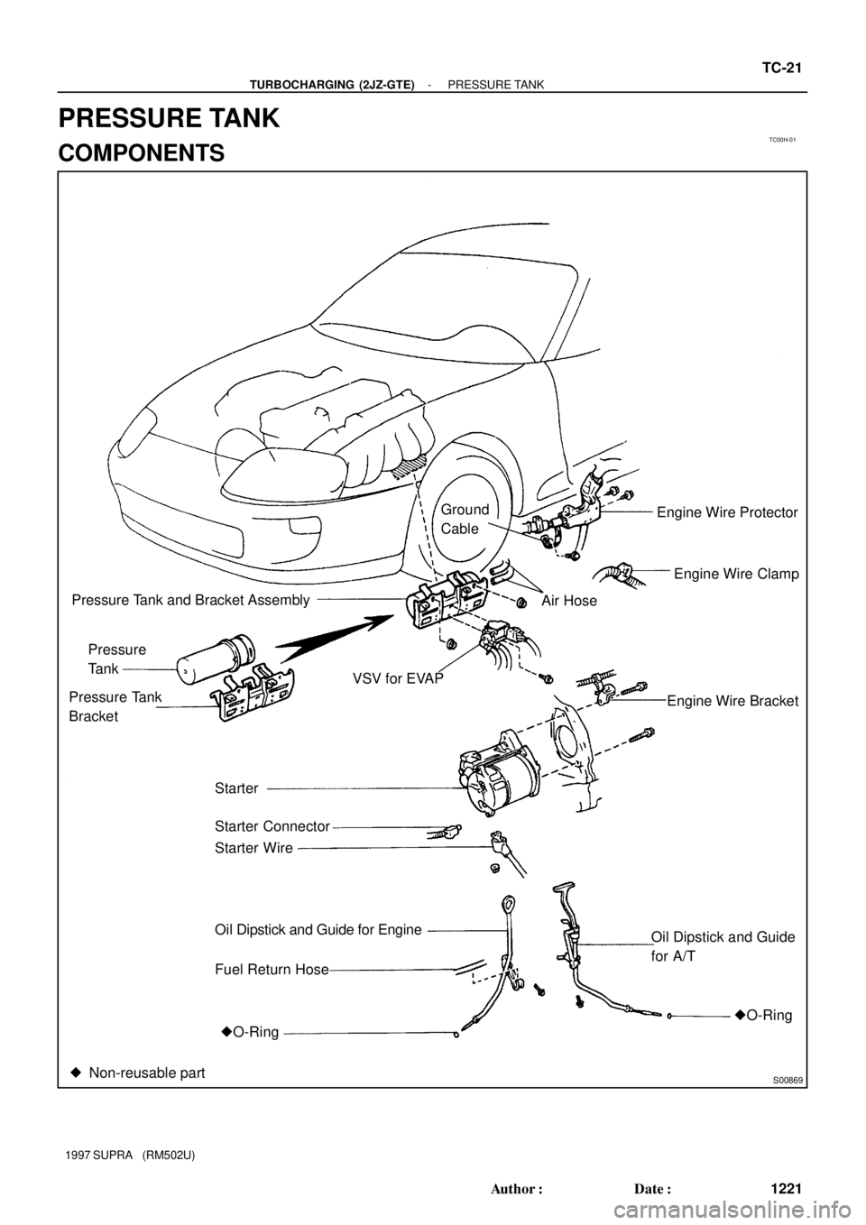
S00869
Engine Wire Protector
Engine Wire Clamp
Engine Wire Bracket VSV for EVAPAir Hose
Oil Dipstick and Guide
for A/T Ground
Cable
�O-Ring Pressure
Tank
Pressure Tank and Bracket Assembly
Starter Pressure Tank
Bracket
Fuel Return Hose Oil Dipstick and Guide for Engine Starter Wire Starter Connector
�O-Ring
� Non-reusable part
- TURBOCHARGING (2JZ-GTE)PRESSURE TANK
TC-21
1221 Author�: Date�:
1997 SUPRA (RM502U)
PRESSURE TANK
COMPONENTS
Page 1806 of 1807
TC00J-01
S00832
No.1 Air Hose
No.2 Air Hose
CAC and Duct Assembly
Engine Under Cover RH Front Fender
Splash Shield Seal
No.2 Engine Under Cover
(W/o Auto Spoiler)x 5 No.2 Air TubeCAC
CAC Duct
No.4 Air Hose
RH Engine Under Cover
(W/ Auto Spoiler)
x16
x 5
x16
x 5 x 6
- TURBOCHARGING (2JZ-GTE)CHARGE AIR COOLER (CAC)
TC-23
1223 Author�: Date�:
1997 SUPRA (RM502U)
CHARGE AIR COOLER (CAC)
COMPONENTS
Page 1807 of 1807

(4)
(3)(1)
P11485
w/o Auto Spoiler
P11996
w/ Auto Spoiler
P13175
w/ Auto Spoiler
Slide TC-24
- TURBOCHARGING (2JZ-GTE)CHARGE AIR COOLER (CAC)
1224 Author�: Date�:
1997 SUPRA (RM5")
TC00K-02
P11995
(2)
(4)
(3)(1)
P11485
w/o Auto Spoiler
P11996
w/ Auto Spoiler
P13175
w/ Auto Spoiler
Slide TC-24
- TURBOCHARGING (2JZ-GTE)CHARGE AIR COOLER (CAC)
1224 Author�: Date�:
1997 SUPRA (RM502U)
REMOVAL
1. REMOVE NO.1 AIR HOSE
2. REMOVE ENGINE UNDER COVER
3. w/o Auto Spoiler:
REMOVE NO.2 ENGINE UNDER COVER
4. REMOVE RH FRONT FENDER SPLASH SHIELD
SEAL
5. w/ Auto Spoiler:
REMOVE RH ENGINE UNDER COVER
6. DISCONNECT AIR HOSE FROM CAC
(a) Remove the 2 bolts holding the No.2 air tube (4) to the
body.
(b) Disconnect these hoses:
(1) No.2 air hose from CAC
(2) No.4 air hose from No.2 air tube
(3) No.3 air hose from CAC
(c) Remove the No.2 air tube (4).
7. w/o Auto Spoiler:
REMOVE CAC AND CAC DUCT ASSEMBLY
Remove the nut, 2 bolts and CAC.
Torque: 13 N´m (135 kgf´cm, 10 ft´lbf)
8. w/ Auto Spoiler:
(a) Fully turn the tire in the illustration direction.
(b) Remove the nut, 2 bolts and CAC.
Torque: 13 N´m (135 kgf´cm, 10 ft´lbf)
HINT:
Remove the CAC between the suspension and body at the il-
lustrated angle of the CAC.
9. REMOVE CAC DUCT FROM CAC
Remove the 4 bolts and CAC duct.
Torque: 4.9 N´m (50 kgf´cm, 43 in.´lbf)
x 5 No.2 Air TubeCAC
CAC Duct
No.4 Air")