Page 1628 of 1807
SA3213
AB
D
Front
C
R06928
R06930
R06914
SA-4
- SUSPENSION AND AXLEFRONT WHEEL ALIGNMENT
1694 Author�: Date�:
1997 SUPRA (RM502U)
4. INSPECT TOE-IN
Toe-in
(Total)A + B: 0° ± 12' (0° ± 0.2°)
C - D: 0 ± 2 mm (0 ± 0.08 in.)
If toe-in is not within specification, adjust by the tie rod end.
5. ADJUST CAMBER AND CASTER
(a) Remove the engine under cover.
(b) Remove the nut, 2 bolts and lower arm bracket stay.
(c) Loosen the front and/or rear adjusting cam nuts.
(d) Adjust the camber and caster by front and/or rear adjust-
ing cams (See adjustment chart).
HINT:
Try to adjust the camber and caster to the center value.
(e) Torque the front and/or rear adjusting cam nuts.
Torque: 226 N´m (2,300 kgf´cm, 166 ft´lbf)
(f) Install the lower arm bracket stay.
Torque:
Bolt: 44 N´m (450 kgf´cm, 32 ft´lbf)
Nut: 59 N´m (600 kgf´cm, 43 ft´lbf)
(g) Install the engine under cover.
6. ADJUST TOE-IN
(a) Remove the boot clamps.
(b) Loosen the tie rod end lock nuts.
Page 1653 of 1807
SA0PC-02
W02908
ABS Speed Sensor
Brake Caliper
Adjusting Cam Plate
Rear Adjusting Cam
Lower Suspension Arm
Engine Under Cover
Non-reusable partFront Adjusting Cam Adjusting Cam Plate
Lower Suspension
Arm Bracket StayStabilizer Bar
Clip Shock Absorber
Bracket
SA-32
- SUSPENSION AND AXLEFRONT LOWER SUSPENSION ARM
1722 Author�: Date�:
1997 SUPRA (RM502U)
FRONT LOWER SUSPENSION ARM
COMPONENTS
Page 1654 of 1807

SA0PD-01
R00159
R07240
SST
R06928
- SUSPENSION AND AXLEFRONT LOWER SUSPENSION ARM
SA-33
1723 Author�: Date�:
1997 SUPRA (RM502U)
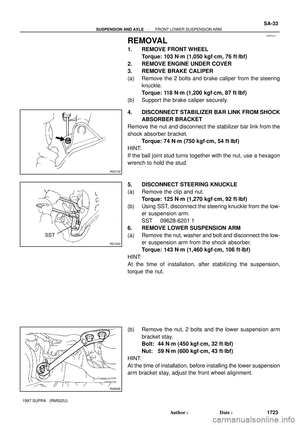
REMOVAL
1. REMOVE FRONT WHEEL
Torque: 103 N´m (1,050 kgf´cm, 76 ft´lbf)
2. REMOVE ENGINE UNDER COVER
3. REMOVE BRAKE CALIPER
(a) Remove the 2 bolts and brake caliper from the steering
knuckle.
Torque: 118 N´m (1,200 kgf´cm, 87 ft´lbf)
(b) Support the brake caliper securely.
4. DISCONNECT STABILIZER BAR LINK FROM SHOCK
ABSORBER BRACKET
Remove the nut and disconnect the stabilizer bar link from the
shock absorber bracket.
Torque: 74 N´m (750 kgf´cm, 54 ft´lbf)
HINT:
If the ball joint stud turns together with the nut, use a hexagon
wrench to hold the stud.
5. DISCONNECT STEERING KNUCKLE
(a) Remove the clip and nut.
Torque: 125 N´m (1,270 kgf´cm, 92 ft´lbf)
(b) Using SST, disconnect the steering knuckle from the low-
er suspension arm.
SST 09628-6201 1
6. REMOVE LOWER SUSPENSION ARM
(a) Remove the nut, washer and bolt and disconnect the low-
er suspension arm from the shock absorber.
Torque: 143 N´m (1,460 kgf´cm, 106 ft´lbf)
HINT:
At the time of installation, after stabilizing the suspension,
torque the nut.
(b) Remove the nut, 2 bolts and the lower suspension arm
bracket stay.
Bolt: 44 N´m (450 kgf´cm, 32 ft´lbf)
Nut: 59 N´m (600 kgf´cm, 43 ft´lbf)
HINT:
At the time of installation, before installing the lower suspension
arm bracket stay, adjust the front wheel alignment.
Page 1657 of 1807
SA0PG-02
R11042
Stabilizer
Bar Link
Stabilizer Bar
Front Fender
Splash Shield
Apron Seal
Engine Under Cover
Apron Seal
Front Fender
Splash Shield Stabilizer Bar Link Bushing
Bracket Bushing
Bracket
- SUSPENSION AND AXLEFRONT STABILIZER BAR
SA-37
1727 Author�: Date�:
1997 SUPRA (RM502U)
FRONT STABILIZER BAR
COMPONENTS
Page 1658 of 1807
SA0PH-01
R07309
R07310
Z18434
Paint Line SA-38
- SUSPENSION AND AXLEFRONT STABILIZER BAR
1728 Author�: Date�:
1997 SUPRA (RM502U)
REMOVAL
1. REMOVE FRONT WHEELS
Torque: 103 N´m (1,050 kgf´cm, 76 ft´lbf)
2. REMOVE ENGINE UNDER COVER
3. REMOVE LEFT AND RIGHT FRONT FENDER SPLASH
SHIELDS
4. REMOVE BOTH STABILIZER BAR LINKS
(a) Remove the 2 nuts and stabilizer bar link from the stabiliz-
er bar and the lower suspension arm.
Torque: 74 N´m (750 kgf´cm, 54 ft´lbf)
HINT:
If the ball joint stud turns together with the nut, use a hexagon
wrench to hold the stud.
(b) Employ the same manner described above to the other
side.
5. REMOVE STABILIZER BAR
(a) Remove the left and right apron seal set bolts.
(b) Remove the 4 bracket bolts and the stabilizer bar with the
2 bushings and brackets.
Torque: 18 N´m (180 kgf´cm, 13 ft´lbf)
6. REMOVE CUSHIONS AND BRACKETS
HINT:
At the time of installation, install the cushion to the outside of the
paint line.
Page 1682 of 1807

SA0PY-02
R06615
Matchmarks
R06904
R06905
- SUSPENSION AND AXLEREAR DIFFERENTIAL CARRIER
SA-65
1755 Author�: Date�:
1997 SUPRA (RM502U)
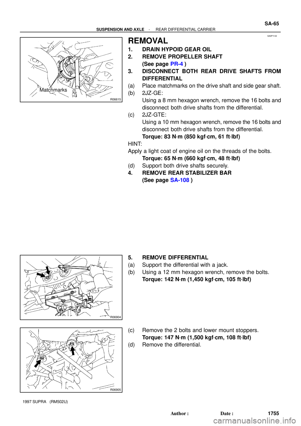
REMOVAL
1. DRAIN HYPOID GEAR OIL
2. REMOVE PROPELLER SHAFT
(See page PR-4)
3. DISCONNECT BOTH REAR DRIVE SHAFTS FROM
DIFFERENTIAL
(a) Place matchmarks on the drive shaft and side gear shaft.
(b) 2JZ-GE:
Using a 8 mm hexagon wrench, remove the 16 bolts and
disconnect both drive shafts from the differential.
(c) 2JZ-GTE:
Using a 10 mm hexagon wrench, remove the 16 bolts and
disconnect both drive shafts from the differential.
Torque: 83 N´m (850 kgf´cm, 61 ft´lbf)
HINT:
Apply a light coat of engine oil on the threads of the bolts.
Torque: 65 N´m (660 kgf´cm, 48 ft´lbf)
(d) Support both drive shafts securely.
4. REMOVE REAR STABILIZER BAR
(See page SA-108)
5. REMOVE DIFFERENTIAL
(a) Support the differential with a jack.
(b) Using a 12 mm hexagon wrench, remove the bolts.
Torque: 142 N´m (1,450 kgf´cm, 105 ft´lbf)
(c) Remove the 2 bolts and lower mount stoppers.
Torque: 147 N´m (1,500 kgf´cm, 108 ft´lbf)
(d) Remove the differential.
Page 1727 of 1807

SS0DK-02
SS-4
- SERVICE SPECIFICATIONSENGINE MECHANICAL (2JZ-GE)
161 Author�: Date�:
1997 SUPRA (RM502U)
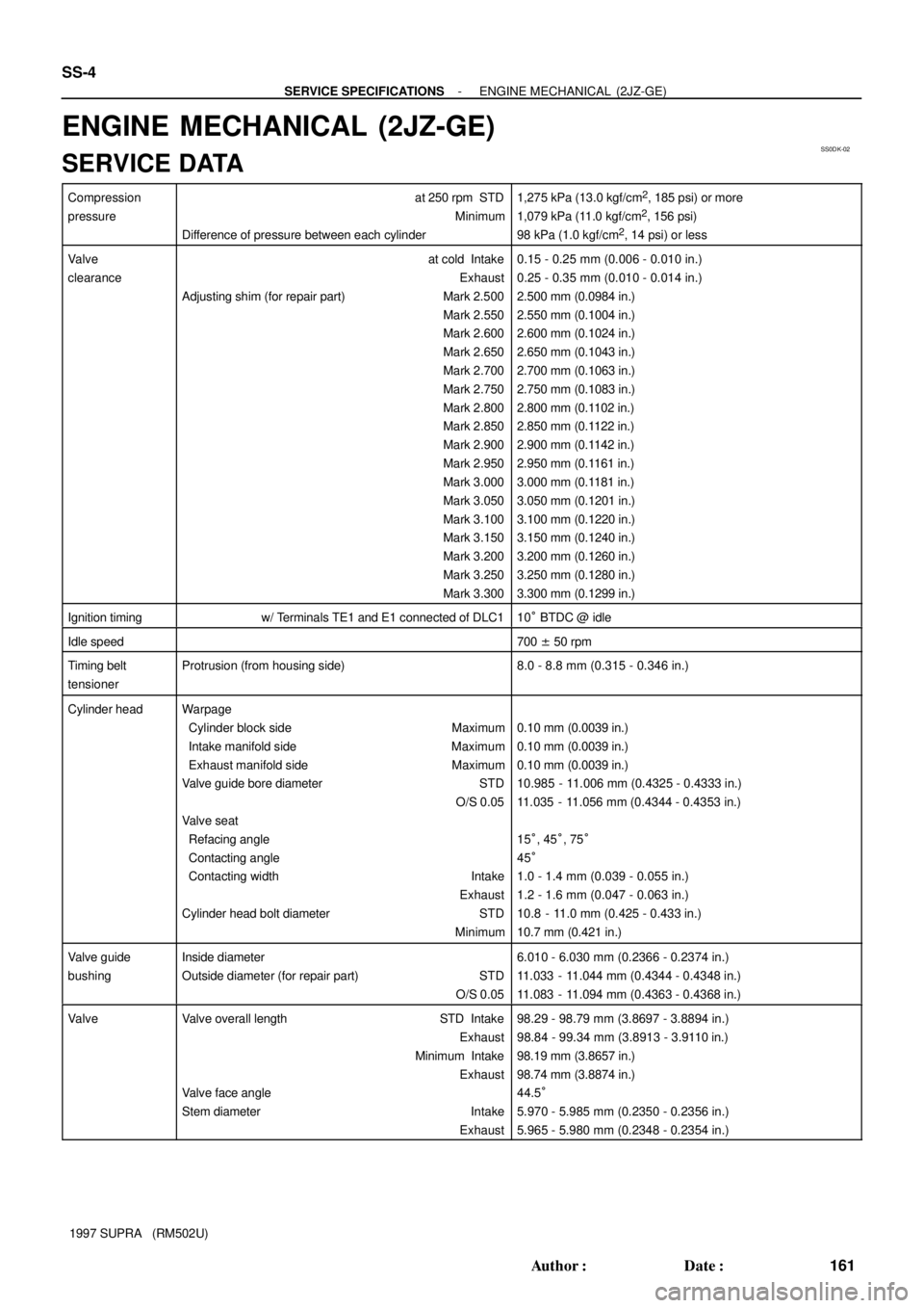
ENGINE MECHANICAL (2JZ-GE)
SERVICE DATA
Compression
pressureat 250 rpm STD
Minimum
Difference of pressure between each cylinder1,275 kPa (13.0 kgf/cm2, 185 psi) or more
1,079 kPa (11.0 kgf/cm2, 156 psi)
98 kPa (1.0 kgf/cm2, 14 psi) or less
Valve
clearanceat cold Intake
Exhaust
Adjusting shim (for repair part) Mark 2.500
Mark 2.550
Mark 2.600
Mark 2.650
Mark 2.700
Mark 2.750
Mark 2.800
Mark 2.850
Mark 2.900
Mark 2.950
Mark 3.000
Mark 3.050
Mark 3.100
Mark 3.150
Mark 3.200
Mark 3.250
Mark 3.3000.15 - 0.25 mm (0.006 - 0.010 in.)
0.25 - 0.35 mm (0.010 - 0.014 in.)
2.500 mm (0.0984 in.)
2.550 mm (0.1004 in.)
2.600 mm (0.1024 in.)
2.650 mm (0.1043 in.)
2.700 mm (0.1063 in.)
2.750 mm (0.1083 in.)
2.800 mm (0.1102 in.)
2.850 mm (0.1122 in.)
2.900 mm (0.1142 in.)
2.950 mm (0.1161 in.)
3.000 mm (0.1181 in.)
3.050 mm (0.1201 in.)
3.100 mm (0.1220 in.)
3.150 mm (0.1240 in.)
3.200 mm (0.1260 in.)
3.250 mm (0.1280 in.)
3.300 mm (0.1299 in.)
Ignition timingw/ Terminals TE1 and E1 connected of DLC110° BTDC @ idle
Idle speed700 ± 50 rpm
Timing belt
tensionerProtrusion (from housing side)8.0 - 8.8 mm (0.315 - 0.346 in.)
Cylinder headWarpage
Cylinder block side Maximum
Intake manifold sideMaximum
Exhaust manifold side Maximum
Valve guide bore diameter STD
O/S 0.05
Valve seat
Refacing angle
Contacting angle
Contacting width Intake
Exhaust
Cylinder head bolt diameter STD
Minimum
0.10 mm (0.0039 in.)
0.10 mm (0.0039 in.)
0.10 mm (0.0039 in.)
10.985 - 11.006 mm (0.4325 - 0.4333 in.)
11.035 - 11.056 mm (0.4344 - 0.4353 in.)
15°, 45°, 75°
45°
1.0 - 1.4 mm (0.039 - 0.055 in.)
1.2 - 1.6 mm (0.047 - 0.063 in.)
10.8 - 11.0 mm (0.425 - 0.433 in.)
10.7 mm (0.421 in.)
Valve guide
bushingInside diameter
Outside diameter (for repair part) STD
O/S 0.056.010 - 6.030 mm (0.2366 - 0.2374 in.)
11.033 - 11.044 mm (0.4344 - 0.4348 in.)
11.083 - 11.094 mm (0.4363 - 0.4368 in.)
ValveValve overall length STD Intake
Exhaust
Minimum Intake
Exhaust
Valve face angle
Stem diameterIntake
Exhaust98.29 - 98.79 mm (3.8697 - 3.8894 in.)
98.84 - 99.34 mm (3.8913 - 3.9110 in.)
98.19 mm (3.8657 in.)
98.74 mm (3.8874 in.)
44.5°
5.970 - 5.985 mm (0.2350 - 0.2356 in.)
5.965 - 5.980 mm (0.2348 - 0.2354 in.)
Page 1728 of 1807

- SERVICE SPECIFICATIONSENGINE MECHANICAL (2JZ-GE)
SS-5
162 Author�: Date�:
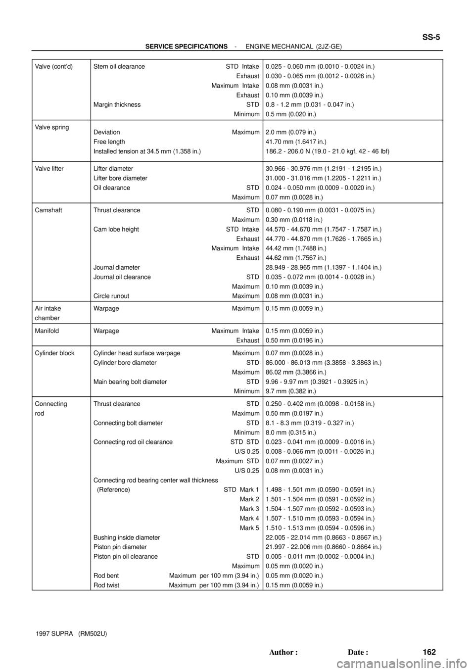
1997 SUPRA (RM502U) Valve (cont'd)
Stem oil clearance STD Intake
Exhaust
Maximum Intake
Exhaust
Margin thickness STD
Minimum0.025 - 0.060 mm (0.0010 - 0.0024 in.)
0.030 - 0.065 mm (0.0012 - 0.0026 in.)
0.08 mm (0.0031 in.)
0.10 mm (0.0039 in.)
0.8 - 1.2 mm (0.031 - 0.047 in.)
0.5 mm (0.020 in.)
Valve springDeviation Maximum
Free length
Installed tension at 34.5 mm (1.358 in.)2.0 mm (0.079 in.)
41.70 mm (1.6417 in.)
186.2 - 206.0 N (19.0 - 21.0 kgf, 42 - 46 lbf)
Valve lifterLifter diameter
Lifter bore diameter
Oil clearance STD
Maximum30.966 - 30.976 mm (1.2191 - 1.2195 in.)
31.000 - 31.016 mm (1.2205 - 1.2211 in.)
0.024 - 0.050 mm (0.0009 - 0.0020 in.)
0.07 mm (0.0028 in.)
CamshaftThrust clearance STD
Maximum
Cam lobe height STD Intake
Exhaust
Maximum Intake
Exhaust
Journal diameter
Journal oil clearance STD
Maximum
Circle runout Maximum0.080 - 0.190 mm (0.0031 - 0.0075 in.)
0.30 mm (0.0118 in.)
44.570 - 44.670 mm (1.7547 - 1.7587 in.)
44.770 - 44.870 mm (1.7626 - 1.7665 in.)
44.42 mm (1.7488 in.)
44.62 mm (1.7567 in.)
28.949 - 28.965 mm (1.1397 - 1.1404 in.)
0.035 - 0.072 mm (0.0014 - 0.0028 in.)
0.10 mm (0.0039 in.)
0.08 mm (0.0031 in.)
Air intake
chamberWarpage Maximum0.15 mm (0.0059 in.)
ManifoldWarpageMaximum Intake
Exhaust0.15 mm (0.0059 in.)
0.50 mm (0.0196 in.)
Cylinder blockCylinder head surface warpage Maximum
Cylinder bore diameter STD
Maximum
Main bearing bolt diameter STD
Minimum0.07 mm (0.0028 in.)
86.000 - 86.013 mm (3.3858 - 3.3863 in.)
86.02 mm (3.3866 in.)
9.96 - 9.97 mm (0.3921 - 0.3925 in.)
9.7 mm (0.382 in.)
Connecting
rodThrust clearance STD
Maximum
Connecting bolt diameter STD
Minimum
Connecting rod oil clearance STD STD
U/S 0.25
Maximum STD
U/S 0.25
Connecting rod bearing center wall thickness
(Reference) STD Mark 1
Mark 2
Mark 3
Mark 4
Mark 5
Bushing inside diameter
Piston pin diameter
Piston pin oil clearance STD
Maximum
Rod bent Maximum per 100 mm (3.94 in.)
Rod twist Maximum per 100 mm (3.94 in.)0.250 - 0.402 mm (0.0098 - 0.0158 in.)
0.50 mm (0.0197 in.)
8.1 - 8.3 mm (0.319 - 0.327 in.)
8.0 mm (0.315 in.)
0.023 - 0.041 mm (0.0009 - 0.0016 in.)
0.008 - 0.066 mm (0.0011 - 0.0026 in.)
0.07 mm (0.0027 in.)
0.08 mm (0.0031 in.)
1.498 - 1.501 mm (0.0590 - 0.0591 in.)
1.501 - 1.504 mm (0.0591 - 0.0592 in.)
1.504 - 1.507 mm (0.0592 - 0.0593 in.)
1.507 - 1.510 mm (0.0593 - 0.0594 in.)
1.510 - 1.513 mm (0.0594 - 0.0596 in.)
22.005 - 22.014 mm (0.8663 - 0.8667 in.)
21.997 - 22.006 mm (0.8660 - 0.8664 in.)
0.005 - 0.011 mm (0.0002 - 0.0004 in.)
0.05 mm (0.0020 in.)
0.05 mm (0.0020 in.)
0.15 mm (0.0059 in.)