Page 1592 of 1807
SR143-01
Z18268
2JZ-GE:
PS Vane Pump
AssemblyOil ReservoirReturn Tube
Battery Clamp
Battery Cover
� Terminal
� Terminal Pressure Feed Tube Air Control Valve
� Gasket
Union Bolt
Drive Belt
Battery
Battery Carrier
Engine Under Cover
x10
� Non-reusable part
- STEERINGPOWER STEERING VANE PUMP
SR-23
1907 Author�: Date�:
1997 SUPRA (RM502U)
POWER STEERING VANE PUMP
COMPONENTS
Page 1593 of 1807
Z18269
2JZ-GTE:
Battery Clamp
Battery Cover
� Terminal
� Terminal
Battery Pressure Feed Tube
� GasketUnion Bolt Drive Belt
Battery Carrier Air Hose No.5
Oil Reservoir to
Pump Hose
PS Vane Pump Assembly
Vane Pump Pulley
Engine Under Cover
x10
� Non-reusable part SR-24
- STEERINGPOWER STEERING VANE PUMP
1908 Author�: Date�:
1997 SUPRA (RM502U)
Page 1595 of 1807

REMOVAL
1. REMOVE ENGINE UNDER COVER
Remove the 10 screws.
2. REMOVE BATTERY
(a) Disco")
SR144-01
R06091
R07429
R07432
SR-26
- STEERINGPOWER STEERING VANE PUMP
1910 Author�: Date�:
1997 SUPRA (RM502U)
REMOVAL
1. REMOVE ENGINE UNDER COVER
Remove the 10 screws.
2. REMOVE BATTERY
(a) Disconnect the 2 terminals.
(b) Remove the bolt, nut and battery clamp.
(c) Remove the battery cover.
(d) Remove the battery and battery carrier.
3. 2JZ-GTE:
REMOVE AIR HOSE No.5
4. REMOVE DRIVE BELT
Loosen the drive belt tension by turning the drive belt tensioner
clockwise, and remove the drive belt.
5. 2JZ-GTE:
DISCONNECT OIL RESERVOIR TO PUMP HOSE
Remove the clip and disconnect the hose.
NOTICE:
Take care not to spill fluid on the A/C compressor rotor.
6. 2JZ-GE:
DISCONNECT RETURN TUBE
NOTICE:
Take care not to spill fluid on the A/C compressor rotor.
7. 2JZ-GTE:
REMOVE VANE PUMP PULLEY
Using SST to stop the pulley rotating, remove the nut.
SST 09960-10010 (09962-01000, 09963-01000)
8. REMOVE PRESSURE FEED TUBE
Using a spanner (24 mm) to hold the pressure port union, re-
move the union bolt and gasket.
9. REMOVE PS VANE PUMP ASSEMBLY
Remove the 2 pump assembly set bolts.
Page 1603 of 1807

INSTALLATION
1. INSTALL PS VANE PUMP ASSEMBLY
Torque the 2 bolts.
Torque:
RH s")
SR148-01
Z09176
Stopper
R07429
R06091
SR-34
- STEERINGPOWER STEERING VANE PUMP
1918 Author�: Date�:
1997 SUPRA (RM502U)
INSTALLATION
1. INSTALL PS VANE PUMP ASSEMBLY
Torque the 2 bolts.
Torque:
RH side bolt: 39 N´m (400 kgf´cm, 29 ft´lbf)
LH side bolt: 58 N´m (590 kgf´cm, 42 ft´lbf)
2. CONNECT PRESSURE FEED TUBE
Using a spanner (24 mm) to hold the pressure port union,
torque the union bolt with a new gasket.
HINT:
Make sure that the stopper of the tube is touching the PS vane
pump assembly as shown, before torquing the union bolt.
Torque: 49 N´m (500 kgf´cm, 36 ft´lbf)
3. 2JZ-GTE:
INSTALL VANE PUMP PULLEY
Using SST to stop the pulley rotating, torque the nut.
SST 09960-10010 (09962-01000, 09663-01000)
Torque: 43 N´m (440 kgf´cm, 32 ft´lbf)
4. 2JZ-GE:
CONNECT RETURN TUBE
5. 2JZ-GTE:
CONNECT OIL RESERVOIR TO PUMP HOSE
Connect the hose and install the clip.
6. INSTALL DRIVE BELT
Loosen the drive belt tension by turning the drive belt tensioner
clockwise, and install the drive belt.
7. 2JZ-GTE:
INSTALL AIR HOSE No.5
8. INSTALL BATTERY
(a) Install the battery carrier and battery.
(b) Install the battery cover.
(c) Install the battery clamp with bolt and nut.
(d) Connect the 2 terminals.
9. INSTALL ENGINE UNDER COVER
Install the 10 screws.
10. BLEED POWER STEERING SYSTEM
(See page SR-3)
Page 1604 of 1807
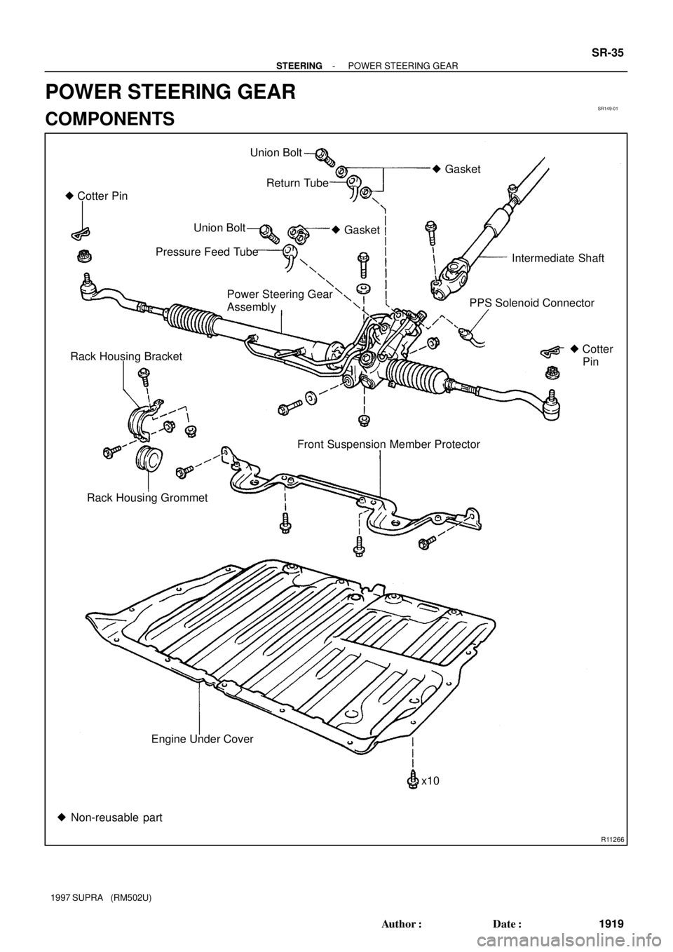
SR149-01
R11266
� Cotter PinUnion Bolt
� Gasket
Return Tube
Union Bolt
Intermediate Shaft � Gasket
Pressure Feed Tube
Power Steering Gear
AssemblyPPS Solenoid Connector
Rack Housing Bracket
Rack Housing Grommet
� Cotter
Pin
Front Suspension Member Protector
Engine Under Cover
x10
� Non-reusable part
- STEERINGPOWER STEERING GEAR
SR-35
1919 Author�: Date�:
1997 SUPRA (RM502U)
POWER STEERING GEAR
COMPONENTS
Page 1607 of 1807
SR14A-01
SR-38
- STEERINGPOWER STEERING GEAR
1922 Author�: Date�:
1997 SUPRA (RM502U)
REMOVAL
1. PLACE FRONT WHEELS FACING STRAIGHT AHEAD
2. REMOVE STEERING WHEEL PAD
(See page SR-1 1)
3. REMOVE STEERING WHEEL
(See page SR-1 1)
4. REMOVE ENGINE UNDER COVER
Remove the 10 bolts.
5. REMOVE FR SUSPENSION MEMBER PROTECTOR
Remove the 4 bolts.
6. DISCONNECT INTERMEDIATE SHAFT
(See page SR-1 1)
7. DISCONNECT RH AND LH TIE ROD ENDS
(See page SA-12)
8. DISCONNECT PRESSURE FEED TUBE
Remove the union bolt and gasket.
9. DISCONNECT RETURN TUBE
Remove the union bolt and 2 gaskets.
10. DISCONNECT PPS SOLENOID CONNECTOR
11. REMOVE RACK HOUSING BRACKET AND GROMMET
Remove the 2 bolts and nuts.
12. REMOVE PS GEAR ASSEMBLY
Remove the 2 bolts and nuts.
Page 1621 of 1807

INSTALLATION
1. INSTALL PS GEAR ASSEMBLY
(a) Temporarily install the 2 bolts and nuts.
(b) After installing the")
SR14E-01
SR-52
- STEERINGPOWER STEERING GEAR
1936 Author�: Date�:
1997 SUPRA (RM502U)
INSTALLATION
1. INSTALL PS GEAR ASSEMBLY
(a) Temporarily install the 2 bolts and nuts.
(b) After installing the rack housing bracket and grommet, torque the 2 bolts and nuts.
Torque: 75 N´m (770 kgf´cm, 55 ft´lbf)
2. INSTALL RACK HOUSING BRACKET AND GROMMET
Torque the 2 bolts and nuts.
Torque: 75 N´m (770 kgf´cm, 55 ft´lbf)
3. CONNECT PPS SOLENOID CONNECTOR
4. CONNECT PRESSURE FEED TUBE
Torque the union bolt over a new gasket.
Torque: 49 N´m (500 kgf´cm, 36 ft´lbf)
5. CONNECT RETURN TUBE
Torque the union bolt over 2 new gaskets.
Torque: 49 N´m (500 kgf´cm, 36 ft´lbf)
6. CONNECT RH AND LH TIE ROD ENDS (See page SA-17)
7. CONNECT INTERMEDIATE SHAFT (See page SR-21)
8. INSTALL FR SUSPENSION MEMBER PROTECTOR
Tighten the 4 bolts.
9. INSTALL ENGINE UNDER COVER
Install the 10 bolts.
10. POSITION FRONT WHEELS FACING STRAIGHT AHEAD
HINT:
Do it with the front of the vehicle jacked up.
11. CENTER SPIRAL CABLE (See page SR-21)
12. INSTALL STEERING WHEEL
(a) Align the matchmarks on the wheel and steering column main shaft.
(b) Temporarily tighten the wheel set nut.
(c) Connect the connector.
13. BLEED POWER STEERING SYSTEM (See page SR-3)
14. CHECK STEERING WHEEL CENTER POINT
15. TORQUE STEERING WHEEL SET NUT
Torque: 35 N´m (360 kgf´cm, 26 ft´lbf)
16. INSTALL STEERING WHEEL PAD (See page SR-21)
17. CHECK FRONT WHEEL ALIGNMENT (See page SA-2)
Page 1624 of 1807

62
- STEERINGPROGRESSIVE POWER STEERING (PPS)
SR-55
1939 Author�: Date�:
1997 SUPRA (RM502U)
(e) Inspect the PPS solenoid valve circuit.
(")
F03098
Wire Harness Side:
R07587
62
R07587
37 mph (60 km/h)
62
- STEERINGPROGRESSIVE POWER STEERING (PPS)
SR-55
1939 Author�: Date�:
1997 SUPRA (RM502U)
(e) Inspect the PPS solenoid valve circuit.
(1) Disconnect the PPS ECU connector.
(2) Check continuity between the terminals of the con-
nector on wire harness side, as shown in the illustra-
tion.
Tester connectionSpecified condition
1 - 6No continuity
2 - 6No continuity
If it is not as specified, repair or replace wire harness or connec-
tor.
(3) Connect the PPS ECU connector.
4. INSPECT PPS ECU
(a) Jack up the vehicle and support it on stands.
(b) Start the engine.
(c) Measure the voltage of ECU.
(1) Using a voltmeter, measure the voltage between
ECU terminals 2 and 6 while the engine is idling.
Standard voltage: 0.15 - 0.20 V
(2) Place the transmission in gear and while running at
about 62 mph (100 km/h), measure the voltage be-
tween ECU terminals 2 and 6.
Standard voltage:
2JZ-GE: 0.06 - 0.17 v
2JZ-GTE: 0.07 - 0.17 v
If no voltage, try another ECU for SUPRA.
(d) Lower the vehicle.