Page 1478 of 1807

SF0GR-01
S04780
Engine Wire
Protector
Air Intake Chamber Stay
IAC Valve Connector
VSV Connector for EGR
Turbo Pressure Sensor Connector
VSV Connector for Fuel Pressure Control
Water Bypass HoseControl Cable Bracket and Cable
Vacuum HoseIAC Valve Pipe
EVAP Hose
� Gasket
EGR Pipe
Brake Booster
Vacuum Hose
Engine
Wire
Protector
Engine Wire Bracket
Engine Wire ClampGround
Cable
EGR Gas Temperature
Sensor Connector
Manifold Stay
No.4 Water Bypass Pipe
Water Bypass Hose Air Intake
Chamber
PS Air Hose Injector Connector
Engine Wire
Clamp
� InsulatorInjector � O - Ring
Vacuum Sensing Hose
Spacer
Delivery Pipe
Fuel Return Pipe
Sub-Throttle Position
Sensor ConnectorInjector Holder
x3
Fuel Inlet Pipe
PCV Hose
Oil Dipstick and Guide for A/T � Gasket
� Gasket
Air Hose
PS Air Hose
Water Bypass Hose
Sub - Throttle Actuator
Connector
Engine Under Cover � Gasket � Insulator
Spacer
Fuel Return Hose Throttle Body
Throttle Position
Sensor ConnectorOil Dipstick and Guide
for Engine� O - Ring
� O - Ring � Gasket
� Gasket
� Non - reusable part
- SFI (2JZ-GTE)INJECTOR
SF-19
1345 Author�: Date�:
1997 SUPRA (RM502U)
COMPONENTS
Page 1479 of 1807
 (2) (3)(4) SF-20
- SFI (2JZ-GTE)INJECTOR
1346 Author�: Date�:
1997 SUPRA")
SF0GS-02
P12565
Pull
O-Ring
S00910
Engine Wire Clamp
O-Ring
Pull
Fuel
Return
Hose
P11322
Chamber
StagCable
Bracket
P11321(1) (2) (3)(4) SF-20
- SFI (2JZ-GTE)INJECTOR
1346 Author�: Date�:
1997 SUPRA (RM502U)
REMOVAL
1. REMOVE ENGINE UNDER COVER
2. REMOVE THROTTLE BODY
(See page SF-43)
3. REMOVE OIL DIPSTICK AND GUIDE FOR A/T
(a) Remove the bolt.
(b) Pull out the dipstick guide together with the dipstick.
HINT:
At the time of installation, please refer to the following items.
Apply clean transmission oil to the O-ring, and push in the dip-
stick guide.
(c) Remove the O-ring from the dipstick guide.
HINT:
At the time of installation, please refer to the following items.
Use a new O-ring.
4. REMOVE OIL DIPSTICK AND GUIDE FOR ENGINE
(a) Disconnect the fuel return hose from the clamp of the dip-
stick guide.
(b) Remove the bolt.
(c) Pull out the dipstick guide together with the dipstick.
HINT:
At the time of installation, please refer to the following items.
Apply clean engine oil to the O-ring, and push in the dipstick
guide.
(d) Remove the O-ring from the dipstick guide.
HINT:
At the time of installation, please refer to the following items.
Use a new O-ring.
5. REMOVE AIR INTAKE CHAMBER STAY
Remove the bolt, nut and chamber stay.
Torque: 19 N´m (195 kgf´cm, 14 ft´lbf)
6. DISCONNECT CONTROL CABLE BRACKET FROM
AIR INTAKE CHAMBER
Remove the 2 bolts, and disconnect the cable bracket from the
air intake chamber.
Torque: 19 N´m (195 kgf´cm, 14 ft´lbf)
7. DISCONNECT CONNECTORS AND HOSES
(a) Disconnect these connectors:
(1) IAC valve connector
(2) Turbo pressure sensor connector
(3) VSV connector for fuel pressure control
(4) VSV connector for EGR
Page 1480 of 1807

(2)
(3) Clamp
P11318(4)
(5)
S04464
(10)
(8)
(6)(7)(9) (11)
S04463
EGR Gas
Temperature
Sensor
Connector
EGR Pipe
- SFI (2JZ-GTE)INJECTOR
SF-21
1347 Author�: Date�:
1997 SUPRA (RM502")
P11991
P11317
(1)
(2)
(3) Clamp
P11318(4)
(5)
S04464
(10)
(8)
(6)(7)(9) (11)
S04463
EGR Gas
Temperature
Sensor
Connector
EGR Pipe
- SFI (2JZ-GTE)INJECTOR
SF-21
1347 Author�: Date�:
1997 SUPRA (RM502U)
(b) Remove the bolt, and disconnect the engine wire protec-
tor from the body.
(c) Disconnect these hoses:
(1) Air hose from IAC valve
Disconnect the IAC valve pipe from the clamp on
the cylinder head cover, and disconnect the air hose
from the IAC valve.
(2) Air hose (from air intake chamber) from
vacuum pipe on IAC valve pipe
(3) Air hose for EGR from valve pipe
(4) PCV hose from PCV valve
(5) Vacuum sensing hose from fuel pressure
regulator
(6) Water bypass hose (from IAC valve) from No.4 wa-
ter bypass pipe
(7) EVAP hose (from air intake chamber) from
vacuum pipe on manifold stay
(8) EVAP hose (from vacuum pipe on No.4 water
bypass pipe) from No.2 vacuum pipe
(9) EVAP hose (from charcoal canister) from No.2
vacuum pipe
(10) PS air hose from air intake chamber
(11) Brake booster vacuum hose from union on air in-
take chamber
8. DISCONNECT EGR GAS TEMPERATURE SENSOR
CONNECTOR
(a) Disconnect the connector from the No.2 vacuum pipe.
(b) Disconnect the sensor connector from the wiring connec-
tor.
9. REMOVE EGR PIPE
(a) Remove the union bolt holding the EGR pipe to the EGR
valve.
Torque: 64 N´m (650 kgf´cm, 47 ft´lbf)
Page 1481 of 1807
 GrayDark
(1)(2)
Gray
(1)Gray
(1)Dark
Gray
(1)(2)
Gray
(1)
Dark
Gray
(1) SF-22
- SFI (2JZ")
P11315
No.4 Water
Bypass Pipe
Manifold Stay
P11314
Clamp
Ground
Cable
S04462
P11312
Water
Hose Bypass
Z09317(3) GrayDark
(1)(2)
Gray
(1)Gray
(1)Dark
Gray
(1)(2)
Gray
(1)
Dark
Gray
(1) SF-22
- SFI (2JZ-GTE)INJECTOR
1348 Author�: Date�:
1997 SUPRA (RM502U)
(b) Remove the 2 bolts, EGR pipe and gasket.
HINT:
At the time of installation, please refer to the following items.
Use a new gasket.
Torque: 27 N´m (280 kgf´cm, 20 ft´lbf)
10. REMOVE NO.4 WATER BYPASS PIPE
Remove the 2 bolts and water bypass pipe.
11. REMOVE MANIFOLD STAY
Remove the 2 bolts and manifold stay.
Torque: 39 N´m (400 kgf´cm, 29 ft´lbf)
12. REMOVE AIR INTAKE CHAMBER ASSEMBLY
(a) Remove the bolt, and disconnect the ground cable from
the intake manifold.
(b) Remove the 2 bolts holding the engine wire protector to
the intake manifold.
(c) Disconnect the 2 clamps of the engine wire protector from
the brackets.
(d) Remove the 5 bolts, 2 nuts and engine wire bracket, and
disconnect the air intake chamber assembly from the in-
take manifold.
HINT:
At the time of installation, please refer to the following items.
Uniformly tighten the bolts and nuts in several passes.
Torque: 27 N´m (280 kgf´cm, 20 ft´lbf)
(e) Disconnect the water bypass hose from the IAC valve.
(f) Remove the gasket.
HINT:
At the time of installation, please refer to the following items.
Use a new gasket.
13. DISCONNECT WIRE CLAMPS AND CONNECTORS
Disconnect these connectors and clamps:
(1) 6 injectors connectors
HINT:
At the time of installation, please refer to the following items.
The No.1, No.3 and No.5 injector connectors are dark gray, and
the No.2, No.4 and No.6 injector connectors are gray.
(2) 2 camshaft position sensor connectors
(3) 3 engine wire clamps from injector holders
Page 1486 of 1807

Connect
P12549
- SFI (2JZ-GTE)INJECTOR
SF-27
1353 Author�: Date�:
1997 SUPRA (RM502U)
(i) Connect the TOYOTA hand-held tester to the DLC3.
(j)")
Q08242
TOYOTA Hand-Held Tester
DLC3
P12548
SST (Wire)
Connect
P12549
- SFI (2JZ-GTE)INJECTOR
SF-27
1353 Author�: Date�:
1997 SUPRA (RM502U)
(i) Connect the TOYOTA hand-held tester to the DLC3.
(j) Turn the ignition switch ON and TOYOTA hand-held tes-
ter main switch ON.
NOTICE:
Do not start the engine.
(k) Select the active test mode on the TOYOTA hand-held
tester.
(l) Please refer to the TOYOTA hand-held tester operator's
manual for further details.
(m) If you have no TOYOTA hand-held tester, connect the
positive (+) and negative (-) leads from the battery to the
fuel pump connector.
(n) Connect SST (wire) to the injector and battery for 15 se-
conds, and measure the injection volume with a gra-
duated cylinder. Test each injector 2 or 3 times.
SST 09842-30060
Injection volume:
111 - 141 cm
3 (6.8 - 8.6 cu in.) per 15 sec.
Difference between each injector:
10 cm
3 (0.6 cu in.) or less
If the injection volume is not as specified, replace the injector.
2. INSPECT LEAKAGE
(a) In the condition above, disconnect the tester probes of
SST (wire) from the battery and check the fuel leakage
from the injector.
SST 09842-30060
Fuel drop:
One drop or less per minutes
(b) Turn the ignition switch to LOCK.
(c) Disconnect the negative (-) terminal cable from the bat-
tery.
(d) Remove the SST.
SST 09268-41046
(e) Reconnect the fuel inlet hose to the fuel filter with 2 new
gaskets and the union bolt.
Torque: 29 N´m (300 kgf´cm, 22 ft´lbf)
(f) Reconnect the fuel return hose to the fuel return pipe.
(g) Remove the 6 bolts, 3 injector holders and 6 insulators.
(h) Disconnect the TOYOTA hand- held tester from the
DLC3.
Page 1488 of 1807
SF0GW-01
P18730
Fuel Pressure Pulsation
Dumper
� Gasket
Starter
Starter ConnectorEngine Wire Bracket
Starter Wire � Gasket
� Non-reusable part SF-30
- SFI (2JZ-GTE)FUEL PRESSURE PULSATION DAMPER
1356 Author�: Date�:
1997 SUPRA (RM502U)
FUEL PRESSURE PULSATION DAMPER
COMPONENTS
Page 1496 of 1807
THROTTLE BODY
1366 Author�: Date�:
1997 SUPRA (RM502U)
THROTTLE BODY
ON-VEHICLE INSPECTION
1. INSPECT THROTT")
P11325
SF0H6-01
P12079
P12560
Turn
Dashpot
Adjusting Screw
Push Rod SF-40
- SFI (2JZ-GTE)THROTTLE BODY
1366 Author�: Date�:
1997 SUPRA (RM502U)
THROTTLE BODY
ON-VEHICLE INSPECTION
1. INSPECT THROTTLE BODY
(a) Check that the throttle linkage moves smoothly.
(b) Check the vacuum at the purge port.
�Start the engine.
�Check the vacuum with your finger.
Port nameAt idleAt 3,000 rpm
PurgeNo vacuumVacuum
2. INSPECT DASHPOT
(a) Warm up engine.
Allow the engine to warm up to normal operating tempera-
ture.
(b) Check idle speed.
Idle speed (Transmission in neutral position):
650 ± 50 rpm
(c) Check and adjust dashpot setting speed.
(1) Disconnect the control cables from the throttle
body.
(2) Turn the throttle linkage until the dashpot adjusting
screw starts to separate from the push rod. Then
keep the throttle linkage at that position.
(3) Check that the dashpot is set.
Dashpot setting speed: 2,300 ± 400 rpm
(4) Reconnect the control cables to the throttle body.
(d) Check VTV operation
(1) Maintain the engine speed at 3,500 rpm.
(2) Release the throttle valve, and check that the en-
gine returns to idle in a few seconds.
Page 1497 of 1807
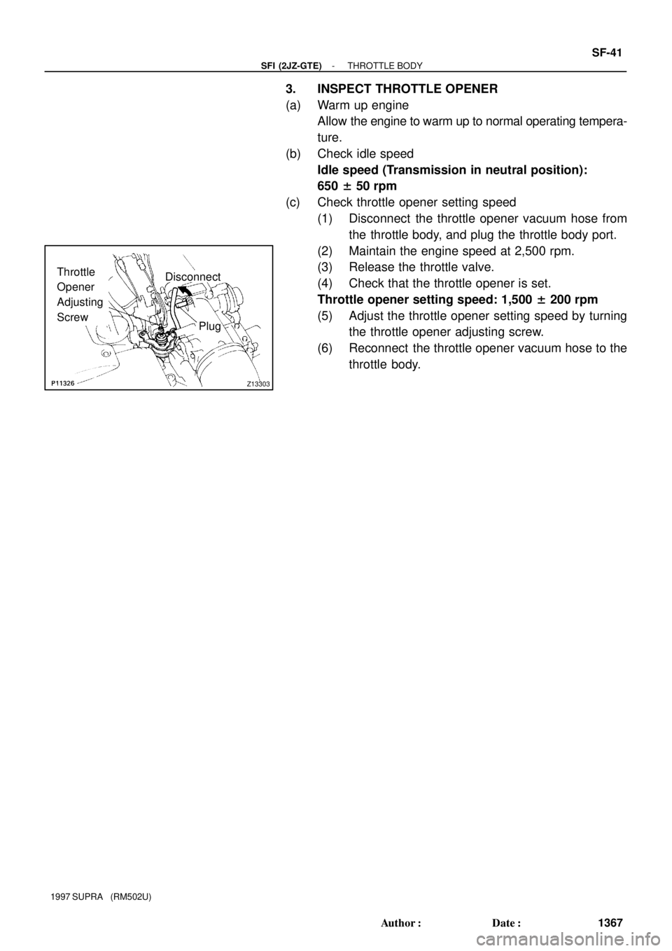
Z13303
Disconnect
PlugThrottle
Opener
Adjusting
Screw
- SFI (2JZ-GTE)THROTTLE BODY
SF-41
1367 Author�: Date�:
1997 SUPRA (RM502U)
3. INSPECT THROTTLE OPENER
(a) Warm up engine
Allow the engine to warm up to normal operating tempera-
ture.
(b) Check idle speed
Idle speed (Transmission in neutral position):
650 ± 50 rpm
(c) Check throttle opener setting speed
(1) Disconnect the throttle opener vacuum hose from
the throttle body, and plug the throttle body port.
(2) Maintain the engine speed at 2,500 rpm.
(3) Release the throttle valve.
(4) Check that the throttle opener is set.
Throttle opener setting speed: 1,500 ± 200 rpm
(5) Adjust the throttle opener setting speed by turning
the throttle opener adjusting screw.
(6) Reconnect the throttle opener vacuum hose to the
throttle body.