Page 1778 of 1807
700
630 - 770
1,000915 - 1,115
2,0001,920 - 2,220
3,0002,890 - 3,350
4,0003,940 - 4,400
5,0005,025 - 5,425
6,5006")
SS-66
- SERVICE SPECIFICATIONSBODY ELECTRICAL
223 Author�: Date�:
1997 SUPRA (RM502U)700
630 - 770
1,000915 - 1,115
2,0001,920 - 2,220
3,0002,890 - 3,350
4,0003,940 - 4,400
5,0005,025 - 5,425
6,5006,650 - 6,950
7,0007,025 - 7,625
OD/TRIP METER
(Connector Connected)
1 - Ground (Ignition switch position ON)Battery positive voltage
4 - Ground (Light Control switch position TAIL or HEAD)Battery positive voltage
5 - 7 (Ignition switch ON and drive the vehicle slowly)0V e Battery positive voltage
6 - 7 (Ignition switch ON and drive the vehicle slowly)0V e more than 5V
8 - Ground (Constant)Battery positive voltage
10 - Ground (Ignition SW ON, Light Control SW TAIL or
HEAD and turn the Light Control Rheostat knob to clockwise)6V " 0V
FUEL RECEIVER GAUGE
Between terminalsResistance (W)
A - BApprox. 269.7
A - CApprox. 123.5
B - CApprox. 146.2
FUEL SENDER GAUGE
Float position: mm (in.)Resistance (W)
F: Approx. 33.8 (1.331)Approx. 4.0
1/2: Approx. 44.8 (1.764)Approx. 55.0
E: Approx. 141.1 (5.555)Approx. 107.0
ENGINE COOLANT TEMPERATURE RECEIVER GAUGE
Between terminalsResistance (W)
A - BApprox. 229.7
A - CApprox. 54.0
B - CApprox. 175.7
ENGINE COOLANT TEMPERATURE SENDER GAUGE
Temperature °C (°F)Resistance (W)
50 (122.0)160 - 240
120 (248.0)17.1 - 21.2
LIGHT FAILURE SENSOR
3 - Ground (Light Control SW position OFF)No voltage
3 - Ground (Light Control SW position TAIL or HEAD)Battery positive voltage
4 - Ground (Ignition SW position LOCK or ACC)No voltage
4 - Ground (Ignition SW position ON)Battery positive voltage
7 - Ground (Stop Light SW position OFF)No voltage
7 - Ground (Stop Light SW position ON)Battery positive voltage
8 - Ground (Engine stop)No voltage
8 - Ground (Engine running)Battery positive voltage
INTEGRATION RELAY
Page 1783 of 1807
SS0CX-01
- SERVICE SPECIFICATIONSAIR CONDITIONING
SS-71
228 Author�: Date�:
1997 SUPRA (RM502U)
TORQUE SPECIFICATION
Part tightnedN´mkgf´cmft´lbf
Compressor x Suction hose101007
Compressor x Discharge hose101007
Compressor x Engine
Stud bolt2626519.2
Other bolts and nut5253038.3
Receiver x Liquid tube5.45548 in.´lbf
Condenser x Liquid tube101007
Condenser x Discharge hose101007
Expansion valve x Evaporator5.45548 in.´lbf
A/C unit x Liquid and suction tube101007
Pressue switch x Liquid tube101007
Condenser upper mounting x Body4.14236 in.´lbf
Pressure plate x Compressor1414010
ECT switch x radiator7.47565 in.´lbf
PS vane pump set bolt5859042
Liquid lines101007
Discharge lines101007
Suction lines101007
Page 1784 of 1807

(Check Procedure and Correction Method)
Check intake air system, and repair or replace parts
as necessary. (See page TC-5)
Check intake air system, and repair or replace part")
TC037-01
(Possible Cause)
(Check Procedure and Correction Method)
Check intake air system, and repair or replace parts
as necessary. (See page TC-5)
Check intake air system, and repair or replace parts
as necessary. (See page TC-5)
Check exhaust system, and repair or replace parts
as necessary. (See page TC-5)
Check exhaust system, and repair or replace parts
as necessary. (See page TC-5) Check turbocharging pressure. (See page TC-5)
Turbocharging pressure:
61 - 75 kPa
(0.62 - 0.76 kgf/cm2, 8.8 - 10.8 psi)
If the pressure is below specifications, begin
diagnosis from item 2.
Check rotation of turbine shaft. If it does not turn or
turns with a heavy drag, replace the turbocharger
assembly.
Check axial and radial play of turbine shaft.
(See page TC-18)
Maximum axial play : 0.110 mm (0.0045 in.)
Maximum radial play: 0.173 mm (0.0068 in.)
If the play is greater than maximum, replace the
turbocharger assembly.
3. LEAK IN INTAKE AIR SYSTEM
4. RESTRICTED EXHAUST SYSTEM
6. ERRATIC TURBOCHARGER 5. LEAK IN EXHAUST SYSTEM
OPERATION 1. TURBOCHARGING PRESSURE
TOO LOW
2. RESTRICTED INTAKE SYSTEM
- TURBOCHARGING (2JZ-GTE)TROUBLESHOOTING
TC-1
1201 Author�: Date�:
1997 SUPRA (RM502U)
TROUBLESHOOTING
PROBLEM SYMPTOMS TABLE
HINT:
Before troubleshooting the turbocharger, first check the engine itself. (Valve clearance, engine compression,
ignition timing etc.)
1. INSUFFICIENT ACCELERATION, LACK OF POWER OR EXCESSIVE FUEL CONSUMPTION
Page 1786 of 1807
TURBOCHARGER
TC-3
1203 Author�: Date�:
1997 SUPRA (RM502U)
TURBOCHARGER
PRECAUTION
1. DO NOT STOP ENGINE IMMEDIATELY AFTER PUL")
TC00A-01
P11285
NO!
P13207
NO!
Ceramic
P11284
- TURBOCHARGING (2JZ-GTE)TURBOCHARGER
TC-3
1203 Author�: Date�:
1997 SUPRA (RM502U)
TURBOCHARGER
PRECAUTION
1. DO NOT STOP ENGINE IMMEDIATELY AFTER PULL-
ING A TRAILER OR AFTER HIGH SPEED OR UPHILL
DRIVING. IDLE ENGINE FOR 20 - 120 SECONDS, DE-
PENDING ON HOW HARD VEHICLE HAS BEEN DRIV-
EN
2. AVOID SUDDEN ACCELERATION OR RACING IM-
MEDIATELY AFTER STARTING A COLD ENGINE
3. DO NOT RUN ENGINE WITH AIR CLEANER RE-
MOVED, AS THIS MAY CAUSE FOREIGN MATERIAL
TO ENTER AND DAMAGE IMPELLER WHEEL OPER-
ATING AT HIGH SPEED
4. IF A TURBOCHARGER IS FOUND TO BE DEFECTIVE
AND MUST BE REPLACED, CHECK FOR CAUSE, AND
REPAIR OR REPLACE FOLLOWING ITEMS AS NEC-
ESSARY
�Engine oil level and quality
�Conditions under which the turbocharger was used
�Oil lines leading to the turbocharger
5. USE CAUTION WHEN REMOVING AND REINSTAL-
LING TURBOCHARGER ASSEMBLY. DO NOT DROP
IT OR KNOCK IT AGAINST ANYTHING OR GRASP IT
BY EASILY-DEFORMED PARTS, SUCH AS ACTUA-
TOR OR ROD, WHEN MOVING IT
6. USE CAUTION WHEN REMOVING AND REINSTAL-
LING EXHAUST GAS CONTROL VALVE ASSEMBLY.
DO NOT DROP IT OR KNOCK IT AGAINST ANYTHING
OR GRASP IT BY EASILY-DEFORMED PARTS, SUCH
AS ACTUATOR OR ROD, WHEN MOVING IT. CON-
TROL VALVE IS CERAMIC
7. BEFORE REMOVING TURBOCHARGER, PLUG IN-
TAKE AND EXHAUST PORTS AND OIL INLET TO PRE-
VENT ENTRY OF DIRT OR OTHER FOREIGN MATERI-
AL
8. IF REPLACING TURBOCHARGER, CHECK FOR AC-
CUMULATION OF SLUDGE PARTICLES IN OIL PIPES,
AND IF NECESSARY, REPLACE OIL PIPES
9. COMPLETELY REMOVE GASKET ADHERED TO LU-
BRICATION OIL PIPE FLANGE AND TURBOCHAR-
GER OIL FLANGE
10. WHEN REPLACING BOLT OR NUTS, USE ONLY AU-
THORIZED REPLACEMENT PARTS TO PREVENT
BREAKAGE OR DEFORMATION
Page 1787 of 1807
P11352
TC-4
- TURBOCHARGING (2JZ-GTE)TURBOCHARGER
1204 Author�: Date�:
1997 SUPRA (RM502U)
11. IF REPLACING TURBOCHARGER, POUR APPROX.
20 cm
3 (1.2 cu in.) OF FRESH OIL INTO TURBOCHAR-
GER OIL INLET AND TURN IMPELLER WHEEL BY
HAND TO SPREAD OIL TO BEARING
12. IF OVERHAULING OR REPLACING ENGINE, CUT
FUEL SUPPLY AFTER REASSEMBLY AND CRANK
ENGINE FOR 30 SECONDS TO DISTRIBUTE OIL
THROUGHOUT ENGINE. THEN ALLOW ENGINE TO
IDLE FOR 60 SECONDS
Page 1788 of 1807
TURBOCHARGER
TC-5
1205 Author�: Date�:
1997 SUPRA (RM502U)
ON-VEHICLE INSPECTION
1. INSPECT INTAKE AIR SYST")
TC00C-01
P13205
Disconnect
Move49 kpa
SST
P12024
61 - 75 kpa
SST
- TURBOCHARGING (2JZ-GTE)TURBOCHARGER
TC-5
1205 Author�: Date�:
1997 SUPRA (RM502U)
ON-VEHICLE INSPECTION
1. INSPECT INTAKE AIR SYSTEM
Check for leakage or clogging between the air cleaner and
turbocharger inlet and between the turbocharger outlet and cyl-
inder head.
�Clogged air cleaner ..Clean or replace air filter
�Hoses collapsed or deformed .... Repair or replace
�Leakage from connections .... Check each
connection and repair
�Cracks in components .... Check and replace
2. INSPECT EXHAUST SYSTEM
Check for leakage or clogging between the cylinder head and
turbocharger inlet and between the turbocharger outlet and ex-
haust pipe.
�Deformed components .... Repair or replace
�Foreign material in passages .... Remove
�Leakage from components .... Repair or replace
�Cracks in components .... Check and replace
3. INSPECT EXHAUST GAS CONTROL
VALVE OPERATION
(a) Disconnect the air hose from the actuator.
(b) Using SST, apply approx. 49 kPa (0.50 kgf/cm
2, 7.1 psi)
of pressure to the actuator.
SST 09992-00242
(c) Check that the actuator push rod moves.
(d) Reconnect the air hose to the actuator.
If operation is not as specified, replace the control valve assem-
bly.
4. INSPECT TURBOCHARGING PRESSURE
(a) Using a 3-way connector, connect SST (turbocharger
pressure gauge) to the hose between the gas filter and
turbo pressure sensor.
SST 09992-00242
(b) While driving with the engine running at 5,600 rpm or
more with the throttle valve fully open in the 1st gear/L
range, check the turbocharging pressure.
Standard pressure:
61 - 75 kPa (0.62 - 0.76 kgf/cm
2, 8.8 - 10.8 psi)
If the pressure is less than that specified, check the intake and
exhaust systems for leakage. If there is no leakage, replace the
turbocharger assembly.
If the pressure is above specification, check if the actuator hose
is disconnected or cracked. If not, replace the turbocharger as-
sembly.
Page 1790 of 1807
TC00D-02
P20891
No.1 Air Hose
Air Cleaner
and MAF Meter
Assembly
Tube Bracket
�Non-reusable Air Cleaner Duct
Theft Deterrent Horn
Tube Clamp
A/T Oil Cooler TubeMAF Meter Connector
Engine Wire Protector
Cruise Control
Actuator Cable
Heat Insulator
for No.2 Front
Exhaust Pipe
Pipe Support Bracket�Gasket
Tube ClampFront Lower Arm
Bracket Stay
Engine Under CoverUpper Front
Crossmember
ExtensionNo.2 Front
Exhaust Pipe
�Gasket
x 16�
��
- TURBOCHARGING (2JZ-GTE)TURBOCHARGER
TC-7
1207 Author�: Date�:
1997 SUPRA (RM502U)
COMPONENTS
Page 1791 of 1807
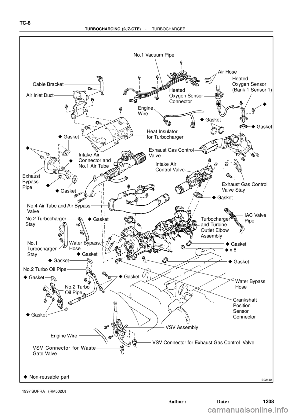
B02440
Cable Bracket
Air Inlet DuctNo.1 Vacuum Pipe
Engine
WireAir Hose
Heated
Oxygen Sensor
(Bank 1 Sensor 1)
� Gasket�
Exhaust Gas Control
Valve Stay
Water Bypass
Hose Heated
Oxygen Sensor
Connector
� Gasket
� Gasket�
�
Crankshaft
Position
Sensor
Connector No.2 Turbocharger
Stay
Water Bypass
Hose Exhaust
Bypass
Pipe
No.4 Air Tube and Air Bypass
Valve
IAC Valve
Pipe Turbocharger
and Turbine
Outlet Elbow
Assembly Heat Insulator
for Turbocharger
Exhaust Gas Control
Valve
Intake Air
Control Valve Intake Air
Connector and
No.1 Air Tube � Gasket
�
��
� Gasket
No.1
Turbocharger
Stay� Gasket
� Gasket
� Gasket
� Gasket � Gasket
No.2 Turbo
Oil Pipe� Gasket No.2 Turbo Oil Pipe� Gasket
x 8 � Gasket
VSV Assembly
VSV Connector for Exhaust Gas Control Valve Engine Wire
VSV Connector for Waste
Gate Valve
� Non-reusable part
TC-8
- TURBOCHARGING (2JZ-GTE)TURBOCHARGER
1208 Author�: Date�:
1997 SUPRA (RM502U)