Page 183 of 1807
Z18226
Personal LightDoor Key Lock and Unlock Switch
Door Lock Motor and Unlock Detection Switch
Luggage Room Light Switch
Luggage Room Light
Door Courtesy Switches Door Lock Motor and
Unlock Detection Switch �R/B No.2Integration
Relay
DOME Fuse
BE0DZ-01
- BODY ELECTRICALINTERIOR LIGHT SYSTEM
BE-27
2005 Author�: Date�:
1997 SUPRA (RM502U)
INTERIOR LIGHT SYSTEM
LOCATION
Page 185 of 1807
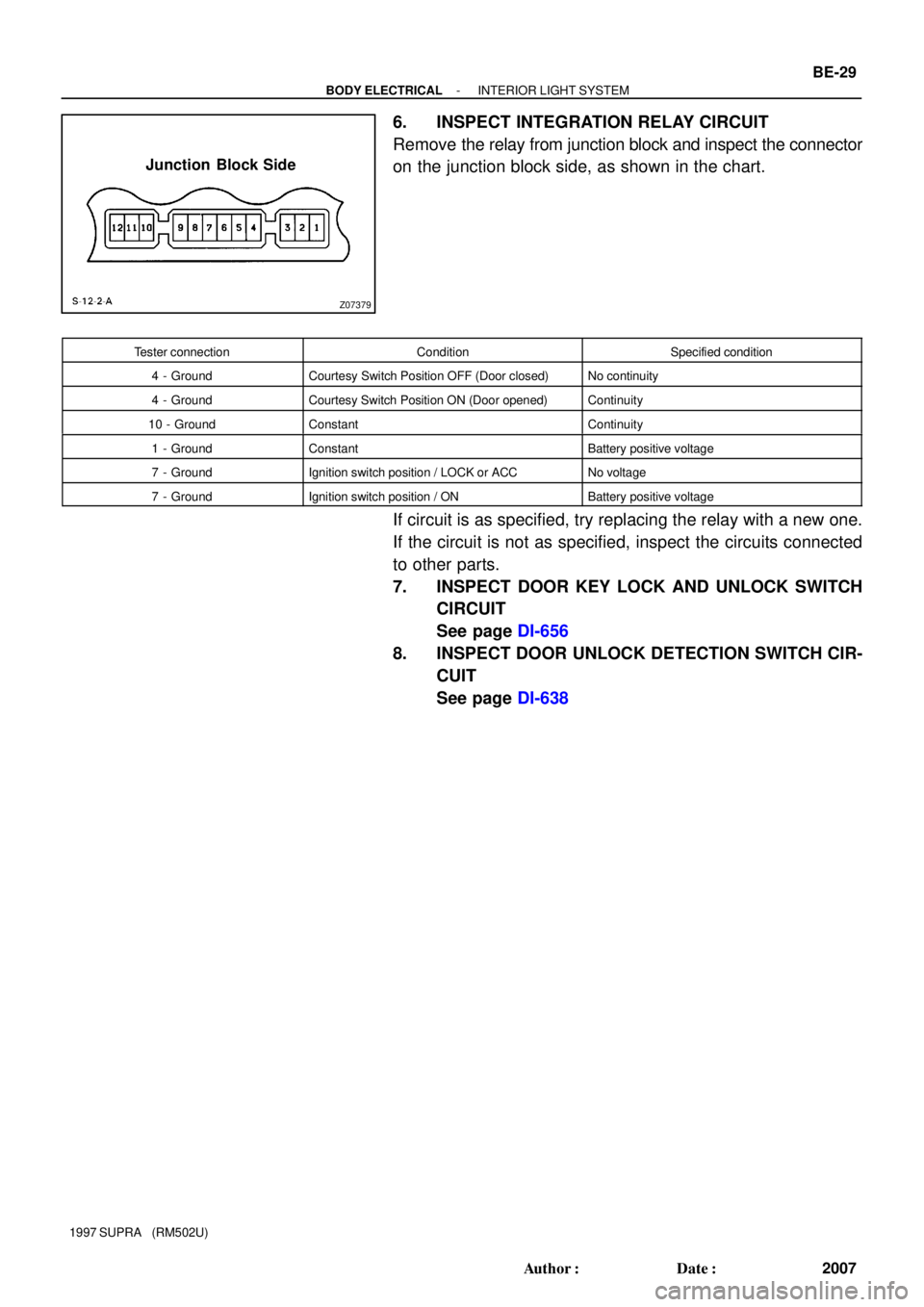
Z07379
Junction Block Side
- BODY ELECTRICALINTERIOR LIGHT SYSTEM
BE-29
2007 Author�: Date�:
1997 SUPRA (RM502U)
6. INSPECT INTEGRATION RELAY CIRCUIT
Remove the relay from junction block and inspect the connector
on the junction block side, as shown in the chart.
Tester connectionConditionSpecified condition
4 - GroundCourtesy Switch Position OFF (Door closed)No continuity
4 - GroundCourtesy Switch Position ON (Door opened)Continuity
10 - GroundConstantContinuity
1 - GroundConstantBattery positive voltage
7 - GroundIgnition switch position / LOCK or ACCNo voltage
7 - GroundIgnition switch position / ONBattery positive voltage
If circuit is as specified, try replacing the relay with a new one.
If the circuit is not as specified, inspect the circuits connected
to other parts.
7. INSPECT DOOR KEY LOCK AND UNLOCK SWITCH
CIRCUIT
See page DI-656
8. INSPECT DOOR UNLOCK DETECTION SWITCH CIR-
CUIT
See page DI-638
Page 198 of 1807

ECM
EC")
I02082I02081
I02080
I02079
I05022
Security Indicator
TRAC OFF Indicator
Low Oil Pressure Warning
Engine Oil Level Warning
Malfunction Indicator
ABS Indicator
No.
Combination Meter (Terminal B2)
ECM
ECM
Low Oil Pressure Warning Switch
Combination Meter (Terminal B4)
TRAC ECU, Traction Solenoid Relay
Ground
Theft Deterrent and Door Lock ECUWire Harness Side
1
2
3
4
5
6
8
9
10
No.Wire Harness Side
GAUGE Fuse
ECU-B Fuse
IGN Fuse
PANEL Fuse
Vehicle Speed Sensor (Terminal 3)
Ground
DOME Fuse
Light Control Rheostat
Combination Meter (Terminal B1)
Generator Terminal
Door Courtesy Switch
Integration Relay (Terminal 9)
Light Failure Sensor Center Airbag Sensor 1
2
3
4
5
6
8
107
11
12
14
15
16
18GAUGE Fuse
PPS ECU, Cruise Control ECU, ECM OD/TRIP
Meter
Open Door Warning
Seat Belt Warning
SRS Warning 8
6 5
3
4
110
2 9
7
10
5
14
18
12
16
15
114
6
1
8
3
2Air Conditioning Amplifier Telltale Light LH:
Telltale Light RH:
Rear Light Warning
Discharge Warning BE-42
- BODY ELECTRICALCOMBINATION METER
2020 Author�: Date�:
1997 SUPRA (RM502U)
2. TELLTALE LIGHT:
Page 200 of 1807

4. INSPECT OD/TRIP METER (in Telltale Lig")
N08931
N08967
Ignition
Switch
Fuel
Gauge
Battery
Z09321
Fuel Gauge
Battery BE-44
- BODY ELECTRICALCOMBINATION METER
2022 Author�: Date�:
1997 SUPRA (RM502U)
4. INSPECT OD/TRIP METER (in Telltale Light RH)
(a) Remove the telltale light with connector still connected.
(b) Check the continuity and voltage.
Tester connectionConditionSpecified condition
7 - Ground*1ConstantContinuity
1 - Ground*1Ignition Switch ºONº positionBattery positive voltage
4 - Ground*1Light Control Switch ºTAILº or ºHEADº
positionBattery positive voltage
5 - 7*1Ignition Switch ON
Drive the vehicle slowly0V e Battery positive voltage
6 - 7*2Ignition Switch ON
Drive the vehicle slowly0V e more than 5V
8 - Ground*1ConstantBattery positive voltage
10 - Ground*1Ignition Switch ON, Light Control Switch TAIL or
HEAD, Turn the light control rheostat knob to
clockwise
6V " 0V
*1: If continuity or voltage are not as specified, check vehicle
side.
*
2: If voltage is not as specified, replace the telltale light.
5. INSPECT FUEL RECEIVER GAUGE OPERATION
(a) Disconnect the connector from the sender gauge assem-
bly.
(b) Turn the ignition switch ON, check that the receiver gauge
needle indicates EMPTY.
(c) Connect terminals 2 and 3 on the wire harness side con-
nector through a 3.4 W test bulb.
(d) Turn the ignition switch ON, and check that the bulb lights
up and that receiver gauge needle moves toward the full
side.
HINT:
Because of the silicon oil in the gauge, it will take a short time
for the needle to stabilize.
If operation is not as specified, inspect the receiver gauge resis-
tance.
Page 205 of 1807

21. INSPECT LIGHT FAILURE")
Z07425
12
10
111 2 345
6
789
Wire Harness Side
Z07426
Ignition
Switch
BatteryWarning Light
- BODY ELECTRICALCOMBINATION METER
BE-49
2027 Author�: Date�:
1997 SUPRA (RM502U)
21. INSPECT LIGHT FAILURE SENSOR CIRCUIT
Disconnect the connector from the sensor and inspect the con-
nector on the wire harness side, as shown.
Tester connectionConditionSpecified condition
1 - GroundConstantContinuity*
2 - GroundConstantContinuity*
9 - GroundConstantContinuity*
10 - GroundConstantContinuity*
11 - GroundConstantContinuity
12 - GroundConstantContinuity*
3 - GroundLight control switch position OFFNo Voltage
3 - GroundLight control switch position TAIL or HEADBattery positive voltage
4 - GroundIgnition switch position LOCK or ACCNo voltage
4 - GroundIgnition switch position ONBattery positive voltage
7 - GroundStop light switch position OFFNo voltage
7 - GroundStop light switch position ONBattery positive voltage
8 - GroundEngine condition StopNo voltage
8 - GroundEngine condition RunningBattery positive voltage
*: There is the resistance because this circuit is grounded
through the bulb.
If circuit is as specified, replace the sensor.
If the circuit is not as specified, inspect the circuits connected
to other parts.
22. INSPECT LIGHT FAILURE WARNING LIGHT
(a) Disconnect the connector from the light failure sensor and
ground terminal 4 on the wire harness side connector.
(b) Start the engine, check that the warning light lights up.
If the warning light does not light up, test the bulb or inspect wire
harness.
Page 207 of 1807

26. INSPECT INTEGRATION RELAY OPERATION
(a) Connect the p")
N08953
N08954
BE6219
Junction Block Side
Connector ºAº
- BODY ELECTRICALCOMBINATION METER
BE-51
2029 Author�: Date�:
1997 SUPRA (RM502U)
26. INSPECT INTEGRATION RELAY OPERATION
(a) Connect the positive (+) lead from the battery to terminals
1 and 7.
(b) Connect the positive (+) lead from the battery to terminal
9 through a 3.4 W test bulb.
(c) Check that the test bulb lights up and buzzer sounds for
4 - 8 seconds when the negative (-) lead from the battery
is connected to terminal 10.
(d) Check that the buzzer sounding in (c) stops when the
negative (-) lead from the battery is connected to terminl
8.
If operation is not as specified, replace the integration relay.
27. INSPECT RELAY CIRCUIT
Remove the relay from the junction block No. 1 and inspect the
connectors on the junction block side.
Tester connectionConditionSpecified condition
4 - GroundDriver's door openContinuity
4 - GroundDriver's door closeNo continuity
5 - GroundIgnition key SetContinuity
5 - GroundIgnition key removeNo continuity
8 - GroundDriver's seat belt fastenContinuity
8 - GroundDriver's seat belt unfastenNo continuity
10 - GroundConstantContinuity
1 - GroundConstantBattery positive voltage
9 - GroundIgnition switch position ONBattery positive voltage
9 - GroundIgnition switch position LOCK or ACCNo Voltage
If circuit is not as specified, tray replacing the relay with a new
one.
Page 216 of 1807
Z09149
BE0EF-01
N08854
BE-60
- BODY ELECTRICALPOWER WINDOW CONTROL SYSTEM
2038 Author�: Date�:
1997 SUPRA (RM502U)
INSPECTION
1. INSPECT POWER WINDOW MASTER SWITCH CON-
TINUITY
Driver 's Switch:
Switch positionTester connectionSpecified condition
UP4 - 10, 8 - 9Continuity
OFF8 - 10, 8 - 9Continuity
DOWN4 - 9, 8 - 10Continuity
Passenger 's Switch (Window unlock):
Switch positionTester connectionSpecified condition
UP4 - 5, 7 - 8Continuity
OFF5 - 8, 7 - 8Continuity
DOWN4 - 7, 5 - 8Continuity
Passenger 's Switch (Window lock):
Switch positionTester connectionSpecified condition
UP4 - 5Continuity
OFF5 - 7Continuity
DOWN4 - 7Continuity
If continuity is not as specified, replace the switch.
2. INSPECT POWER WINDOW MASTER SWITCH ILLU-
MINATION
Connect the positive (+) lead from the battery to terminal 4 and
the negative (-) lead to terminal 8, check that the illumination
lights up.
If operation is not as specified, replace the master switch.
Page 218 of 1807

5. INSPECT POWER WINDOW SWITCH CONTINUITY
Switch positionTester connect")
Z10792
N09810
N09811
N09812
N09813
BE-62
- BODY ELECTRICALPOWER WINDOW CONTROL SYSTEM
2040 Author�: Date�:
1997 SUPRA (RM502U)
5. INSPECT POWER WINDOW SWITCH CONTINUITY
Switch positionTester connectionSpecified condition
UP1 - 4, 3 - 5Continuity
OFF1 - 2, 3 - 5Continuity
DOWN1 - 2, 3 - 4Continuity
If continuity is not as specified, replace the switch.
6. Driver 's Door:
INSPECT POWER WINDOW MOTOR OPERATION
(a) Connect the positive (+) lead from the battery to terminal
1 and the negative (-) lead to terminal 2, and check that
the motor turns clockwise.
(b) Reverse the polarity, and check that the motor turns coun-
terclockwise.
If operation is not as specified, replace the motor.
7. Passenger 's Door:
INSPECT POWER WINDOW MOTOR OPERATION
(a) Connect the positive (+) lead from the battery to terminal
1 and the negative (-) lead to terminal 2, and check that
the motor turns clockwise.
(b) Reverse the polarity, and check that the motor turns coun-
terclockwise.
If operation is not as specified, replace the motor.