Page 321 of 1807
 BO-68
- BODYSEAT BELT
2148 Author�: Date�:
1997 SUPRA (RM502U)
INSPECTION
CAUTION:
Replace the seat belt assembly (ou")
BO0RU-01
BO0632
BO0633
15°
45°
N10070
Full belt length minus
200 mm (7.87 in.) BO-68
- BODYSEAT BELT
2148 Author�: Date�:
1997 SUPRA (RM502U)
INSPECTION
CAUTION:
Replace the seat belt assembly (outer belt, inner belt, bolts
or nuts and sill-bar) if it has been used in a severe impact.
The entire assembly should be replaced even if damage is
not obvious.
Emergency Locking Retractor (ELR) and Automatic Lock-
ing Retractor (ALR) type
1. All seat belts:
RUNNING TEST (IN SAFE AREA)
(a) Fasten the front seat belts.
(b) Drive the car at 10 mph (16 km/h) and make a very hard
stop.
Check that the belt locks and cannot be extended at this
time.
HINT:
Conduct this test in a safe area. If the belt does not lock, remove
the belt mechanism assembly and conduct the following static
check. Also, whenever installing a new belt assembly, verify the
proper operation before installation.
2. Driver 's seat belt (ELR):
STATIC TEST
(a) Make sure that the belt locks when pulled out quickly.
(b) Remove the locking retractor assembly.
(c) Tilt the retractor slowly.
(d) Make sure that the belt can be pulled out at a tilt of 15 de-
grees or less, and cannot be pulled out over 45 degrees
of tilt.
If a problem is found, replace the assembly.
3. Except driver's seat belt (ALR/ ELR):
STATIC TEST
(a) Make sure that the belt locks when pulled out quickly.
(b) Remove the locking retractor assembly.
(c) Pull out the whole belt and measure the length of the
whole belt.
Then retract the belt slightly and pull it out again.
(d) Make sure that the belt cannot be extended further.
If a problem is found, replace the assembly.
(e) Retract the whole belt, then pull out the belt until 200 mm
(7.87 in.) of belt remains retracted.
(f) Tilt the retractor slowly.
(g) Make sure that the belt can be pulled out at a tilt of 15 de-
grees or less, and cannot be pulled out at over 45 degrees
of tilt.
If a problem is found, replace the assembly.
Page 325 of 1807

BRAKE FLUID
BLEEDING
HINT:
If any work is done on the brake system or if air in the brake lines")
BR0GB-01
W02787
W02788
W02789
N00759
- BRAKEBRAKE FLUID
BR-5
1805 Author�: Date�:
1997 SUPRA (RM502U)
BRAKE FLUID
BLEEDING
HINT:
If any work is done on the brake system or if air in the brake lines
is suspected, bleed the system of air.
NOTICE:
Do not let brake fluid remain on painted surfaces. Wash it
off immediately.
1. REMOVE RESERVOIR CAP
2. FILL RESERVOIR WITH BRAKE FLUID
Fluid: SAE J1703 or FMVSS No.116DOT3
3. BLEED MASTER CYLINDER
HINT:
If the master cylinder has been disassembled or if the reservoir
becomes empty, bleed the master cylinder.
(a) Disconnect the brake lines from the master cylinder.
(b) Slowly depress the brake pedal and hold it.
(c) Block off the outer holes with your fingers, and release the
brake pedal.
(d) Repeat (b) 3 or 4 times.
4. BLEED BRAKE LINE
(a) Connect the vinyl tube to the brake caliper.
(b) Depress the brake pedal several times, then loosen the
bleeder plug with the pedal held down.
(c) At the point when fluid stops coming out, tighten the
bleeder plug, then release the brake pedal.
(d) Repeat (b) and (c) until all the air in the fluid has been bled
out.
Torque: (Bleeder plug)
11 N´m (110 kgf´cm, 8 ft´lbf)
Page 327 of 1807

BRAKE PEDAL
ON-VEHICLE INSPECTION
1. CHECK THA")
R07175
Stop Light Switch
Push Rod
Pedal HeightBR1AW-01
BR4980
A
R00085
Pedal Freeplay
- BRAKEBRAKE PEDAL
BR-7
1807 Author�: Date�:
1997 SUPRA (RM502U)
BRAKE PEDAL
ON-VEHICLE INSPECTION
1. CHECK THAT PEDAL HEIGHT IS CORRECT
Pedal height from asphalt sheet:
154.2 - 164.2 mm (6.071 - 6.465 in.)
If the pedal height is incorrect, adjust it.
2. IF NECESSARY, ADJUST PEDAL HEIGHT
(a) Remove the lower instrument panel and finish panel.
(b) Disconnect the connector from the stop light switch.
(c) Loosen the stop light switch lock nut and remove the stop
light switch.
(d) Loosen the push rod lock nut.
(e) Adjust the pedal height by turning the pedal push rod.
(f) Tighten the push rod lock nut.
Torque: 25 N´m (260 kgf´cm, 19 ft´lbf)
(g) Install the stop light switch and turn it until it lightly con-
tacts the pedal stopper.
(h) Turn the stop light switch back one turn.
(i) Check the clearance (A) between stop lights switch and
pedal.
Clearance: 0.5 - 2.4 mm (0.020 - 0.094 in.)
(j) Tighten the stop light switch lock nut.
(k) Connect the connector to the stop light switch.
(l) Check that the stop lights come on when the brake pedal
is depressed, and go off when the brake pedal is re-
leased.
(m) After adjusting the pedal height, check the pedal freeplay.
If clearance (A) between the stop light switch and the brake
pedal stopper has been adjusted correctly, the pedal freeplay
will meet the specifications.
(n) Install the lower instrument panel and finish panel.
3. CHECK PEDAL FREEPLAY
(a) Stop the engine and depress the brake pedal several
times until there is no more vacuum left in the booster.
(b) Push in the pedal by hand until the second point of resis-
tance begins to be felt, then measure the distance, as
shown.
Pedal freeplay: 1 - 6 mm (0.04 - 0.24 in.)
If incorrect, check the stop light switch clearance. If the clear-
ance is OK, then troubleshoot the brake system.
Page 329 of 1807

PARKING BRAKE LEVER
ON-VEHICLE INSPECTION
1. CHECK PARKING BRAKE LEVER TRAVEL")
R07116
BR0GD-01
R07117
Lock Nut
Adjusting Nut
- BRAKEPARKING BRAKE LEVER
BR-9
1809 Author�: Date�:
1997 SUPRA (RM502U)
PARKING BRAKE LEVER
ON-VEHICLE INSPECTION
1. CHECK PARKING BRAKE LEVER TRAVEL
Pull the parking brake lever all the way up, and count the num-
ber of clicks.
Parking brake lever travel at 196 N (20 kgf, 44.1 lbf):
5 - 8 clicks
If incorrect, adjust the parking brake.
2. IF NECESSARY, ADJUST PARKING BRAKE
HINT:
Before adjusting the parking brake, make sure that the rear
brake shoe clearance has been adjusted. For shoe clearance
adjustment, see page BR-64.
(a) Remove the upper console panel.
(b) Remove the screw and parking brake hole cover.
(c) Using a socket driver and spanner wrench, remove the
adjusting lock nut.
(d) Turn the adjusting nut until the lever travel is correct.
(e) Install the adjusting lock nut.
(f) Using a socket driver and spanner wrench, tighten the ad-
justing lock nut.
Torque: 5.4 N´m (55 kgf´cm, 48 in.´lbf)
(g) Install the parking brake hole cover with the screw.
(h) Install the upper console panel.
Page 334 of 1807
R12236
A BR-14
- BRAKEBRAKE MASTER CYLINDER
1814 Author�: Date�:
1997 SUPRA (RM502U)
(c) Place a rag and 2 wooden blocks on the work table and
lightly tap the cylinder flange against the block edges until
the piston drops out of the cylinder.
HINT:
Make sure the distance (A) from the rag to the top of the blocks
is at least 100 mm (3.94 in.).
Page 343 of 1807
BR0GZ-01
R07130
R07131
- BRAKEFRONT BRAKE CALIPER (2JZ-GTE)
BR-37
1837 Author�: Date�:
1997 SUPRA (RM502U)
REMOVAL
1. REMOVE FRONT WHEEL
2. DISCONNECT FLEXIBLE HOSE
(a) Remove the union bolt and 2 gaskets from the caliper,
then disconnect the flexible hose from the caliper.
Torque: 30 N´m (310 kgf´cm, 22 ft´lbf)
HINT:
At the time of installation, please refer to the following item.
Install the flexible hose lock securely in the lock hole in the cali-
per.
(b) Use a container to catch the brake fluid as it drains out.
3. REMOVE CALIPER
Remove the 2 mounting bolts and caliper.
Torque: 118 N´m (1,200 kgf´cm, 87 ft´lbf)
4. REMOVE THESE PARTS
(a) Clip and 2 pins
(b) Anti-rattle spring
(c) 2 pads
(d) 2 pad spacers and anti-squeal shims
Page 350 of 1807
BR0HF-01
R07153
R07154
- BRAKEREAR BRAKE CALIPER (2JZ-GTE)
BR-55
1855 Author�: Date�:
1997 SUPRA (RM502U)
REMOVAL
1. REMOVE REAR WHEEL
2. DISCONNECT FLEXIBLE HOSE
(a) Remove the union bolt and 2 gaskets from the caliper,
then disconnect the flexible hose from the caliper.
Torque: 30 N´m (310 kgf´cm, 22 ft´lbf)
HINT:
At the time of installation, please refer to the following item.
Install the flexible hose lock securely in the lock hole in the cali-
per.
(b) Use a container to catch the brake fluid.
3. REMOVE CALIPER
Remove the 2 mounting bolts and caliper.
Torque: 104 N´m (1,065 kgf´cm, 77 ft´lbf)
4. REMOVE THESE PARTS
(a) Clip
(b) 2 pins
(c) Anti-rattle spring
(d) 2 pads
(e) 4 anti-squeal shims
Page 357 of 1807
BR0HN-02
BR5358
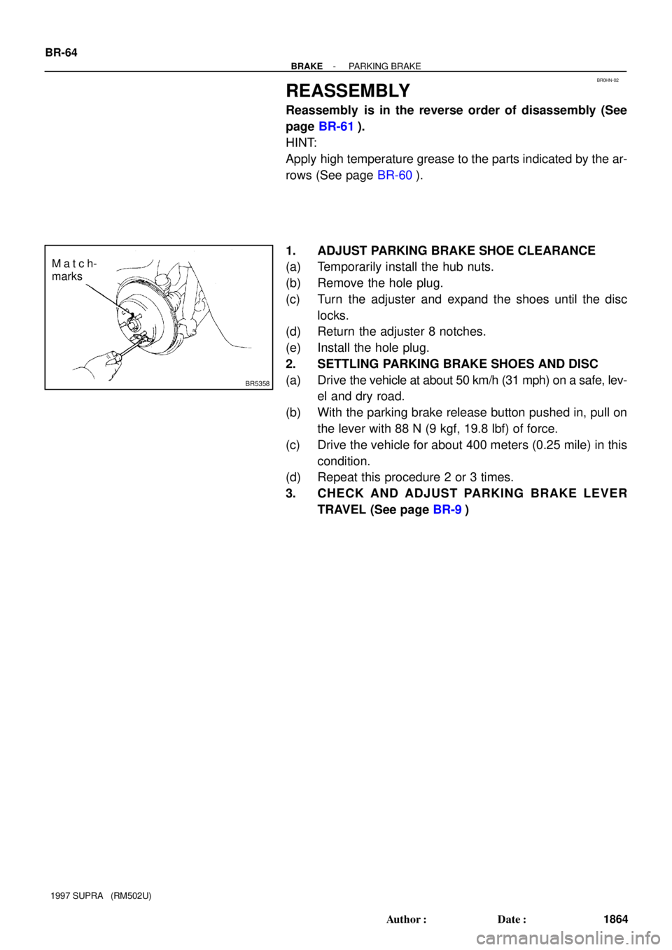
Match-
marks BR-64
- BRAKEPARKING BRAKE
1864 Author�: Date�:
1997 SUPRA (RM502U)
REASSEMBLY
Reassembly is in the reverse order of disassembly (See
page BR-61).
HINT:
Apply high temperature grease to the parts indicated by the ar-
rows (See page BR-60).
1. ADJUST PARKING BRAKE SHOE CLEARANCE
(a) Temporarily install the hub nuts.
(b) Remove the hole plug.
(c) Turn the adjuster and expand the shoes until the disc
locks.
(d) Return the adjuster 8 notches.
(e) Install the hole plug.
2. SETTLING PARKING BRAKE SHOES AND DISC
(a) Drive the vehicle at about 50 km/h (31 mph) on a safe, lev-
el and dry road.
(b) With the parking brake release button pushed in, pull on
the lever with 88 N (9 kgf, 19.8 lbf) of force.
(c) Drive the vehicle for about 400 meters (0.25 mile) in this
condition.
(d) Repeat this procedure 2 or 3 times.
3. CHECK AND ADJUST PARKING BRAKE LEVER
TRAVEL (See page BR-9)