Page 487 of 1807

FOR THE TOYOTA DEALER
COLLISION REPAIR INFORMATION
TITLE: SRS AIRBAG COMPONENT REPLACEMENT PAGE 1 of 6
SECTION: ELECTRICAL BULLETIN #79
MODELS: ALL
DATE: AUGUST 1997
After an airbag has been deployed during a collision, it will be necessary to replace certain
components of the airbag system. Technicians can identify these parts by using the
attached matrix.
If the airbag does not deploy, yet the combination meter (airbag warning light) stays on for
more that 10 seconds after the key is turned to the ªACCº or ªONº position, it is necessary
to perform a diagnostic test. Always refer to the Toyota repair manual for the correct repair
procedure.
The attached information includes:
�A matrix indicating components requiring replacement (pages 2±4).
�Parts replacement note (page 5).
�An example repair manual page outlining the diagnostic procedure available in
each model specific repair manual (page 6).
Toyota recommends the use of electrical repair kit (P/N 00002±04200±01) for any wiring
repairs. This kit includes a selection of numerous repair connectors, terminal ends, a repair
procedures manual and special tools specific to Toyota. The
replacement electrical wire
and connector (from the wire harness to the front sensors) is P/N 82988±24010.
Toyota also offers a video package which shows the operation of the SRS airbag system
(P/N 00401±42994).
CAUTION: SRS Airbag service work can be performed only AFTER 90 SECONDS
from the time the ignition switch is turned to the ªlockº position and the
negative (±) terminal cable is disconnected from the battery.
NOTE: PLEASE ROUTE THIS BULLETIN TO YOUR COLLISION REPAIR CENTER
MANAGER!
Page 494 of 1807
SRS COMPONENT REPLACEMENT (cont'd) PAGE 2 of 4
CAUTION: SRS Airbag service work can be performed only AFTER 90 SECONDS
from the time the ignition switch is turned to the ªlockº position and the
negative (±) terminal cable is disconnected from the battery.
This is an example from a Toyota Repair Manual. Always refer to the repair manual
applicable to the model and year of the vehicle you are diagnosing.
Page 497 of 1807

FOR THE TOYOTA DEALER
COLLISION REPAIR INFORMATION
TITLE: SRS AIRBAG COMPONENT REPLACEMENT PAGE 1 of 6
SECTION: ELECTRICAL BULLETIN #79
MODELS: ALL
DATE: AUGUST 1997
After an airbag has been deployed during a collision, it will be necessary to replace certain
components of the airbag system. Technicians can identify these parts by using the
attached matrix.
If the airbag does not deploy, yet the combination meter (airbag warning light) stays on for
more that 10 seconds after the key is turned to the ªACCº or ªONº position, it is necessary
to perform a diagnostic test. Always refer to the Toyota repair manual for the correct repair
procedure.
The attached information includes:
�A matrix indicating components requiring replacement (pages 2±4).
�Parts replacement note (page 5).
�An example repair manual page outlining the diagnostic procedure available in
each model specific repair manual (page 6).
Toyota recommends the use of electrical repair kit (P/N 00002±04200±01) for any wiring
repairs. This kit includes a selection of numerous repair connectors, terminal ends, a repair
procedures manual and special tools specific to Toyota. The
replacement electrical wire
and connector (from the wire harness to the front sensors) is P/N 82988±24010.
Toyota also offers a video package which shows the operation of the SRS airbag system
(P/N 00401±42994).
CAUTION: SRS Airbag service work can be performed only AFTER 90 SECONDS
from the time the ignition switch is turned to the ªlockº position and the
negative (±) terminal cable is disconnected from the battery.
NOTE: PLEASE ROUTE THIS BULLETIN TO YOUR COLLISION REPAIR CENTER
MANAGER!
Page 529 of 1807

CO0ZY-01
Z07402
Drain Plug
Drain Plug CO-2
- COOLINGCOOLANT
1415 Author�: Date�:
1997 SUPRA (RM502U)
REPLACEMENT
1. DRAIN ENGINE COOLANT
(a) Remove the radiator cap.
CAUTION:
To avoid the danger of being burned, do not remove the ra-
diator cap while the engine and radiator are still hot, as fluid
and steam can be blown out under pressure.
(b) Loosen the 2 drain plugs (for the engine and radiator),
and drain the coolant.
HINT:
To prevent the coolant from spraying over the cylinder block,
connect the rubber hose (inside diameter 6 - 8 mm) in the mar-
ket to the union pipe under.
(c) Close the drain plugs.
Torque:
Engine drain plug
29 N´m (300 kgf´cm, 22 ft´lbf)
2. FILL ENGINE COOLANT
(a) Slowly fill the system with coolant.
�Use a good brand of ethylene-glycol base coolant
and mix it according to the manufacturer's direc-
tions.
�Using coolant which includes more than 50 % ethyl-
ene-glycol (but not more than 70 %) is recom-
mended.
NOTICE:
�Do not use an alcohol type coolant.
�The coolant should be mixed with demineralized wa-
ter or distilled water.
Capacity (w/ Heater):
M/TA/T
2JZ-GE7.3 liters
(7.7 US qts, 6.4 lmp. qts)8.3 liters
(8.8 US qts, 7.3 lmp. qts)
2JZ-GTE8.9 liters
(9.4 US qts, 7.8 lmp. qts)8.8 liters
(9.3 US qts, 7.7 lmp. qts)
(b) Install the radiator cap.
(c) Start the engine, and bleed the cooling system.
(d) Refill the reservoir with coolant until it reaches the
ºFULLº line.
3. CHECK ENGINE COOLANT FOR LEAKS
Page 534 of 1807

CO08M-02
P12278
P12300Turn
- COOLINGWATER PUMP
CO-7
1420 Author�: Date�:
1997 SUPRA (RM502U)
REMOVAL
1. 2JZ-GTE:
REMOVE NO.1 AIR HOSE
2. 2JZ-GE:
REMOVE AIR CLEANER, MAF METER AND INTAKE
AIR CONNECTOR PIPE ASSEMBLY
(See page EM-57)
3. 2JZ-GTE:
REMOVE AIR CLEANER AND MAF METER
ASSEMBLY (See page EM-58)
4. REMOVE RADIATOR ASSEMBLY
(See page CO-22)
5. 2JZ-GTE M/T:
REMOVE DRIVE BELT TENSIONER DAMPER
(See page EM-15)
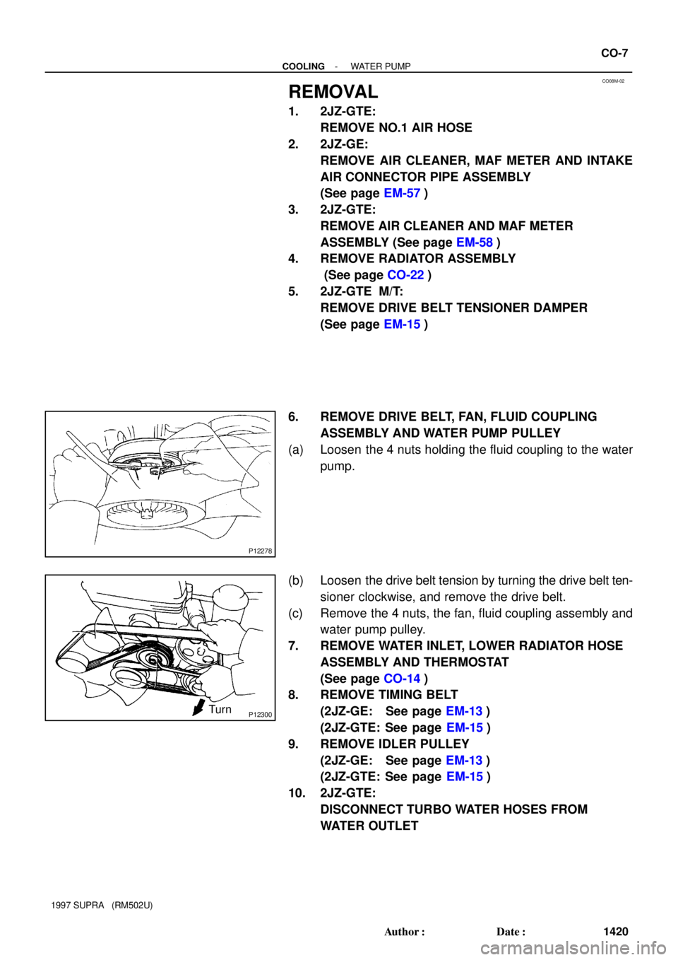
6. REMOVE DRIVE BELT, FAN, FLUID COUPLING
ASSEMBLY AND WATER PUMP PULLEY
(a) Loosen the 4 nuts holding the fluid coupling to the water
pump.
(b) Loosen the drive belt tension by turning the drive belt ten-
sioner clockwise, and remove the drive belt.
(c) Remove the 4 nuts, the fan, fluid coupling assembly and
water pump pulley.
7. REMOVE WATER INLET, LOWER RADIATOR HOSE
ASSEMBLY AND THERMOSTAT
(See page CO-14)
8. REMOVE TIMING BELT
(2JZ-GE: See page EM-13)
(2JZ-GTE: See page EM-15)
9. REMOVE IDLER PULLEY
(2JZ-GE: See page EM-13)
(2JZ-GTE: See page EM-15)
10. 2JZ-GTE:
DISCONNECT TURBO WATER HOSES FROM
WATER OUTLET
Page 536 of 1807
P25846
Drain Hose
- COOLINGWATER PUMP
CO-9
1422 Author�: Date�:
1997 SUPRA (RM502U)
(f) Remove the 6 bolts, water pump and gasket.
(g) Remove the drain hose.
(h) Remove the O-ring from the cylinder block.
Page 538 of 1807

CO08O-01
P03945
New
O-Ring
P02574
New Gasket
S00913
A
B A
B
AB
BB
- COOLINGWATER PUMP
CO-1 1
1424 Author�: Date�:
1997 SUPRA (RM502U)
INSTALLATION
1. INSTALL WATER PUMP
(a) Install a new O-ring to the cylinder block.
(b) Install the drain hose.
(c) Install a new gasket to the water pump.
(d) Connect the water pump to the water bypass pipe. Do not
install the nut yet.
(e) Install the water pump with the 2 bolts (A) and 4 bolts (B).
Torque: 21 N´m (210 kgf´cm, 15 ft´lbf)
HINT:
Hand tighten the (A) bolts first.
(f) Install the 2 nuts holding the No.2 water bypass pipe to
the water pump.
Torque: 21 N´m (210 kgf´cm, 15 ft´lbf)
(g) 2JZ-GTE:
Connect the No.3 turbo water hose to the water pump.
(h) 2JZ-GE:
Install the connector bracket (for crankshaft position sen-
sor connector) with the bolt.
(i) 2JZ-GE:
Install the engine clamp bracket with the bolt.
(j) Install the generator with the bolt and nut.
Torque: 40 N´m (400 kgf´cm, 30 ft´lbf)
2. 2JZ-GE:
INSTALL NO.1 WATER BYPASS PIPE AND
WATER BYPASS OUTLET
(a) Install 2 new O-rings to the No.1 water bypass pipe.
(b) Install a new O-ring and the water bypass outlet with the
2 bolts.
Torque: 9.0 N´m (90 kgf´cm, 80 in.´lbf)
3. 2JZ-GTE:
INSTALL NO.1 WATER BYPASS PIPE AND
WATER OUTLET
(a) Install 2 new O-rings to the No.1 water bypass pipe.
(b) Apply soapy water to the O-rings.
(c) Install the No.1 water bypass pipe to the water pump.
Page 539 of 1807

P02583
Matchmarks CO-12
- COOLINGWATER PUMP
1425 Author�: Date�:
1997 SUPRA (RM502U)
(d) Install a new gasket and the water outlet with the 2 bolts.
Torque: 21 N´m (210 kgf´cm, 15 ft´lbf)
(e) Connect the ECT sensor and sender gauge connectors.
4. 2JZ-GTE:
CONNECT TURBO WATER HOSES TO WATER
OUTLET
5. INSTALL IDLER PULLEY AND TIMING BELT
(2JZ-GE: See page EM-19)
(2JZ-GTE: See page EM-21)
6. INSTALL WATER INLET AND LOWER RADIATOR
HOSE ASSEMBLY (See page CO-16)
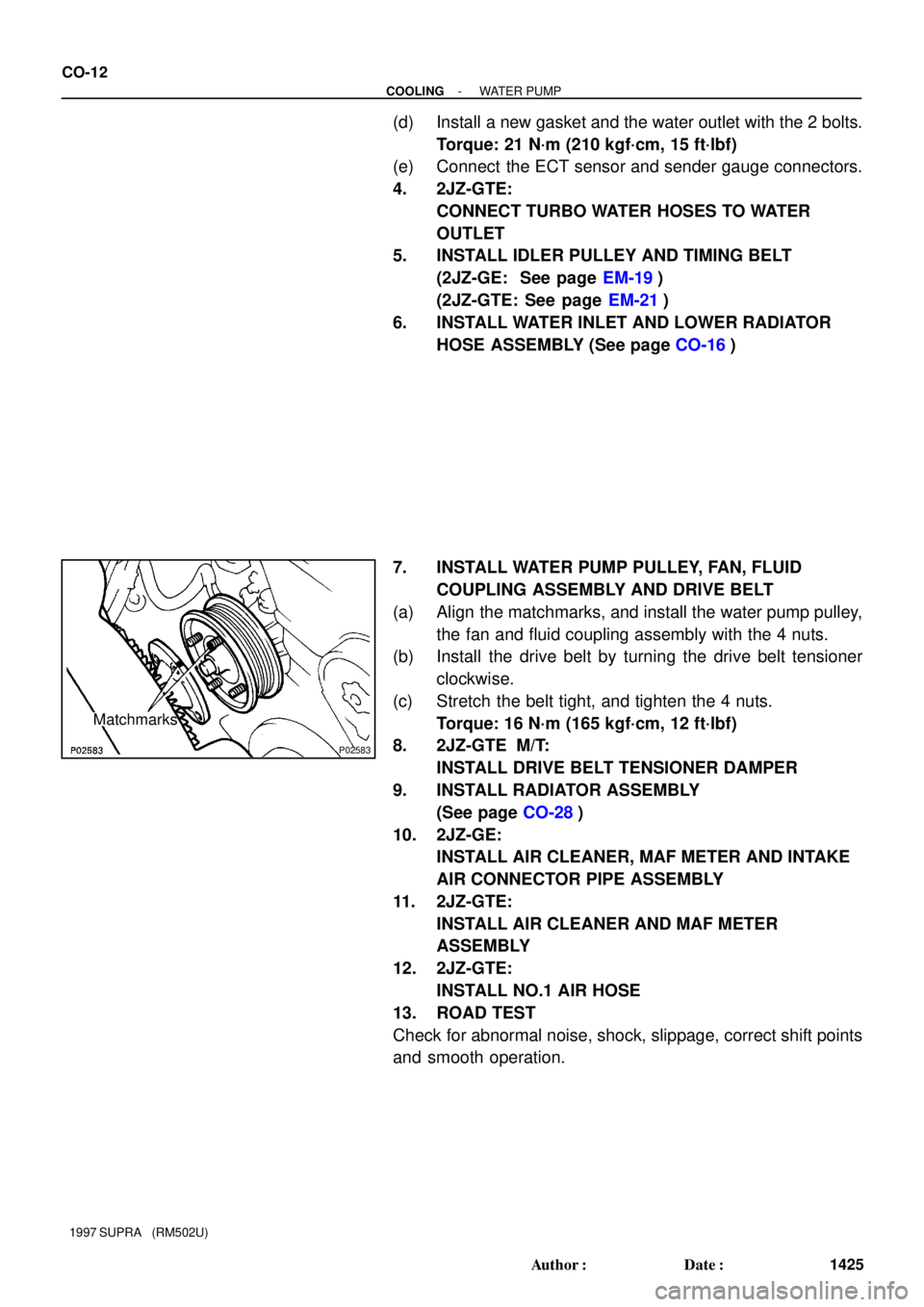
7. INSTALL WATER PUMP PULLEY, FAN, FLUID
COUPLING ASSEMBLY AND DRIVE BELT
(a) Align the matchmarks, and install the water pump pulley,
the fan and fluid coupling assembly with the 4 nuts.
(b) Install the drive belt by turning the drive belt tensioner
clockwise.
(c) Stretch the belt tight, and tighten the 4 nuts.
Torque: 16 N´m (165 kgf´cm, 12 ft´lbf)
8. 2JZ-GTE M/T:
INSTALL DRIVE BELT TENSIONER DAMPER
9. INSTALL RADIATOR ASSEMBLY
(See page CO-28)
10. 2JZ-GE:
INSTALL AIR CLEANER, MAF METER AND INTAKE
AIR CONNECTOR PIPE ASSEMBLY
11. 2JZ-GTE:
INSTALL AIR CLEANER AND MAF METER
ASSEMBLY
12. 2JZ-GTE:
INSTALL NO.1 AIR HOSE
13. ROAD TEST
Check for abnormal noise, shock, slippage, correct shift points
and smooth operation.